Week 16: Applications and Implications
Introduction

The Photo-Podoscope is designed to help healthcare professionals capture detailed images of patients' feet. By using a computerized interface, professionals can move the camera and adjust the lighting to obtain high-quality images for accurate diagnoses. This device aims to improve the quality of foot diagnosis, making it more accessible and affordable, especially in resource-limited communities.
Who has done what beforehand?
Previous devices in the market offer similar functionality but often come with high costs and complex setups, making them less accessible to smaller clinics or communities. However, there has been ongoing innovation in the field of medical imaging, with various teams working on improving the accuracy and affordability of diagnostic tools. The Photo-Podoscope builds on these advancements by offering a cost-effective and easy-to-replicate solution.
What will I design?
I designed the entire Photo-Podoscope system from scratch. This includes the robust MDF structure that supports the patient, an acrylic platform where the patient stands, and a 3D-printed camera mechanism using PLA and PETG. Additionally, I developed a computerized interface to control the camera movement and lighting, and designed a custom PCB using the Xiao Seed RP2040 microcontroller.
Materials and Components
| Component | Qty | Approximate Cost (USD) | Link/Where will they come from |
|---|---|---|---|
| MDF (15 mm) | 2 sheets | 50 | Provided by IBERO Puebla FAB Lab |
| Acrylic sheet (8 mm x 600 mm x 400 m) | 1 sheet | 75 | Provided by IBERO Puebla FAB Lab |
| PLA filament | 1 spool | 25 | Provided by IBERO Puebla FAB Lab |
| PETG filament | 1 spool | 30 | Provided by IBERO Puebla FAB Lab |
| NEMA 17 stepper motor | 1 | 15 | Provided by IBERO Puebla FAB Lab |
| Xiao Seed RP2040 microcontroller | 1 | 10 | Provided by IBERO Puebla FAB Lab |
| 5m LED strip | 1 | 15 | JAMS Electronica |
| Mosfet | 2 | 3 | Provided by IBERO Puebla FAB Lab |
| PCB board | 1 | 5 | Provided by IBERO Puebla FAB Lab |
| CNC router service | 1 service | N/A | Provided by IBERO Puebla FAB Lab |
| 3D printing service | 1 service | N/A | Provided by IBERO Puebla FAB Lab |
Processes Used
The construction of the Photo-Podoscope involves several manufacturing processes. CNC router cutting is used for the MDF structure, while the Roland SRM-20 machine is employed to create the PCB from a copper plate. The camera mechanism is produced using 3D printing. Additionally, the software for the microcontroller is developed using Arduino IDE and Python with TKinter.
Questions to be Answered
Before finalizing the project, it is crucial to address the mechanical resistance of the structure. To do so, I conducted a finite element analysis based on a 100 kg limit using SolidWorks.
Finite Element Analysis
To create the finite element analysis, I used SolidWorks with the following parameters:
- Materials: Select individual parts in the simulation tree, right-click, and choose "Apply/Edit Material." Select the appropriate material from the material library and apply it. In my case, it is MDF and acrylic.
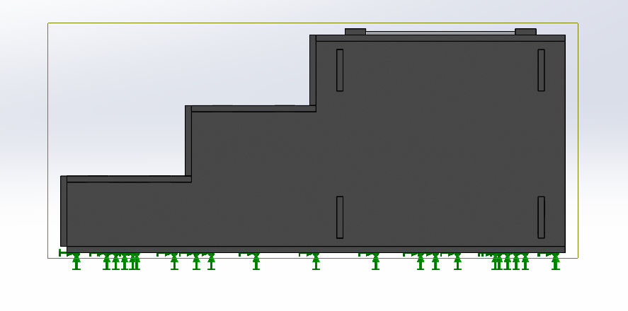
- Boundary Conditions: Define how the model is held or constrained. This can include fixtures, slides, or any other restrictions. Click on "Fixtures" and apply the necessary boundary conditions. In my case, the model will be fixed on the bottom surface as it is the part where the model touches the ground.
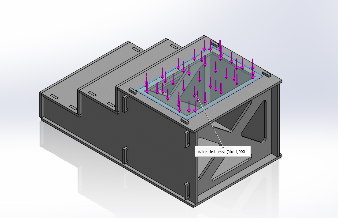
- Loads: Add the forces, pressures, or loads applied to your model. Click on "External Loads" and select the type and magnitude of the load. For this case, I used 1000N and applied it on the acrylic sheet.


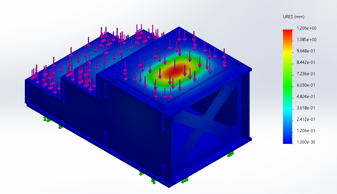
Once those variables are set, we run the finite element and have the following results:
Displacement
The system will present a maximum displacement of 1.2 mm on the center of the acrylic sheet, which does not represent a risk for the patient. However, in future iterations, a thicker material can be used to diminish this value. This analysis ensures that our patient will be safe in the mechanism.

Evaluation
The Photo-Podoscope will be evaluated based on its imaging accuracy, ease of use, affordability, and durability. Field tests with healthcare professionals will provide feedback on its practicality and effectiveness in clinical settings. Additionally, comparisons with existing devices will help assess its performance and value proposition.

