Output Devices
For this week, the main goal is to understand and add an output device to a microcontroller board I’ve designed previously and program it to do something. As a group, we've done some research this week on the power consumption of an Output device, take a look at three different devices. Individually, this week I will design my PCB for the final project on this week. The main PCB will have a Microcontroller Xiao Seed RP2040, an A4988 Driver for a stepper motor, and a LED output controlled by a Transistor to make sure the 12V input can power the LED strip.
Bill of Materials
| Component | Qty | Approximate Cost (USD) |
|---|---|---|
| XIAO Seeed RP2040 Microcontroller | 1 | $6.00 |
| NEMA 17 Stepper Motor | 1 | $15.00 |
| A4988 Stepper Motor Driver | 1 | $3.00 |
| MOSFET (IRF520) | 2 | $1.50 |
| LED Strip (White, 12V) | 2 | $10.00 |
| 12V Power Supply | 1 | $10.00 |
| DC-DC Buck Converter (5V output) | 1 | $3.00 |
| PCB (Custom Designed) | 1 | $10.00 |
| Jumper Wires | 1 set | $5.00 |
| Connectors (various types) | 1 set | $5.00 |
| Resistors (Assorted) | 1 set | $2.00 |
| Capacitors (Assorted) | 1 set | $2.00 |
| Heat Shrink Tubing | 1 set | $2.00 |
PCB Schematic
The PCB was designed in KiCad as I learned on Week 10. You can take a look to see more details on the process.
The PCB will have the Xiao Seed RP2040 D7 and D8 Pins connected to the Driver A4988 Step and Direction. The D0 pin will send the on/off signal to the transistor and a 5V and general GND will also be taken from the Microcontroller.
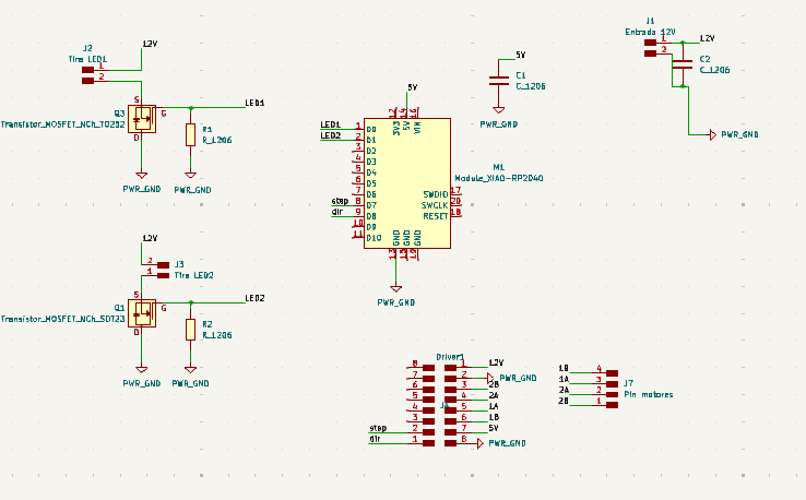
As always, a good practice is to have a decoupling capacitor in both 5V and 12V and the GND. I decided to use N-type transistors as they can act as switches in electronic circuits for future steps in the project. When a voltage is applied to the gate (above a certain threshold), the transistor allows current to flow between the drain and source terminals, effectively "turning on" the switch. When the gate voltage is removed or below the threshold, the current flow stops, "turning off" the switch.
PCB Footprint
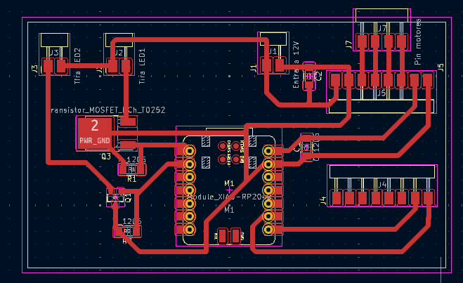
As the PCB will handle up to 12V, I opted to create a thicker trace than previous weeks, this to ensure the current would be handled correctly. To calculate the trace width I used the Calculator that gave me a recommended size of 1mm.
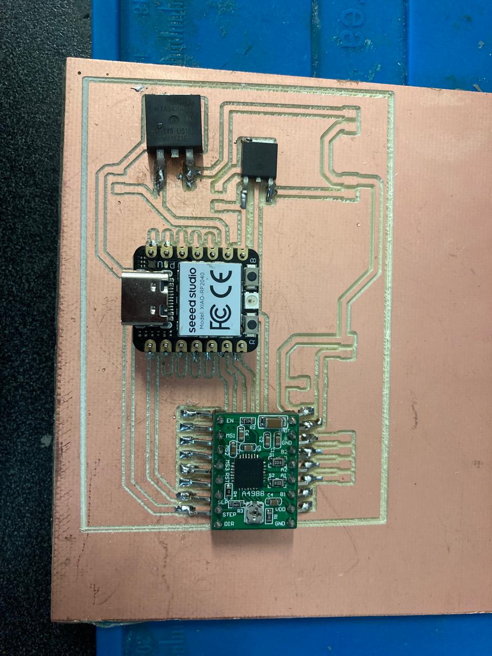
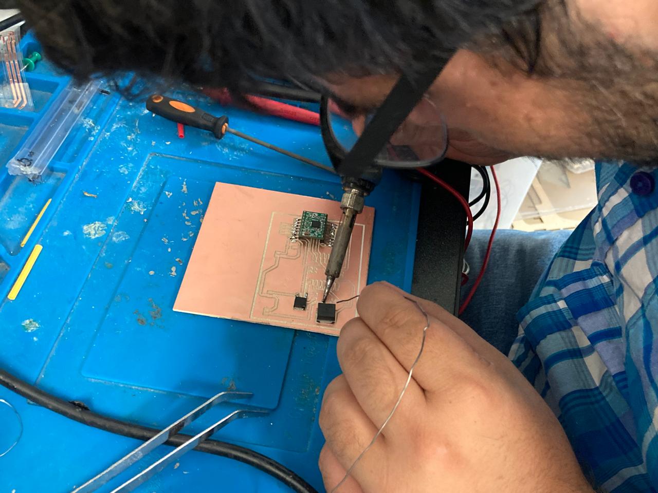
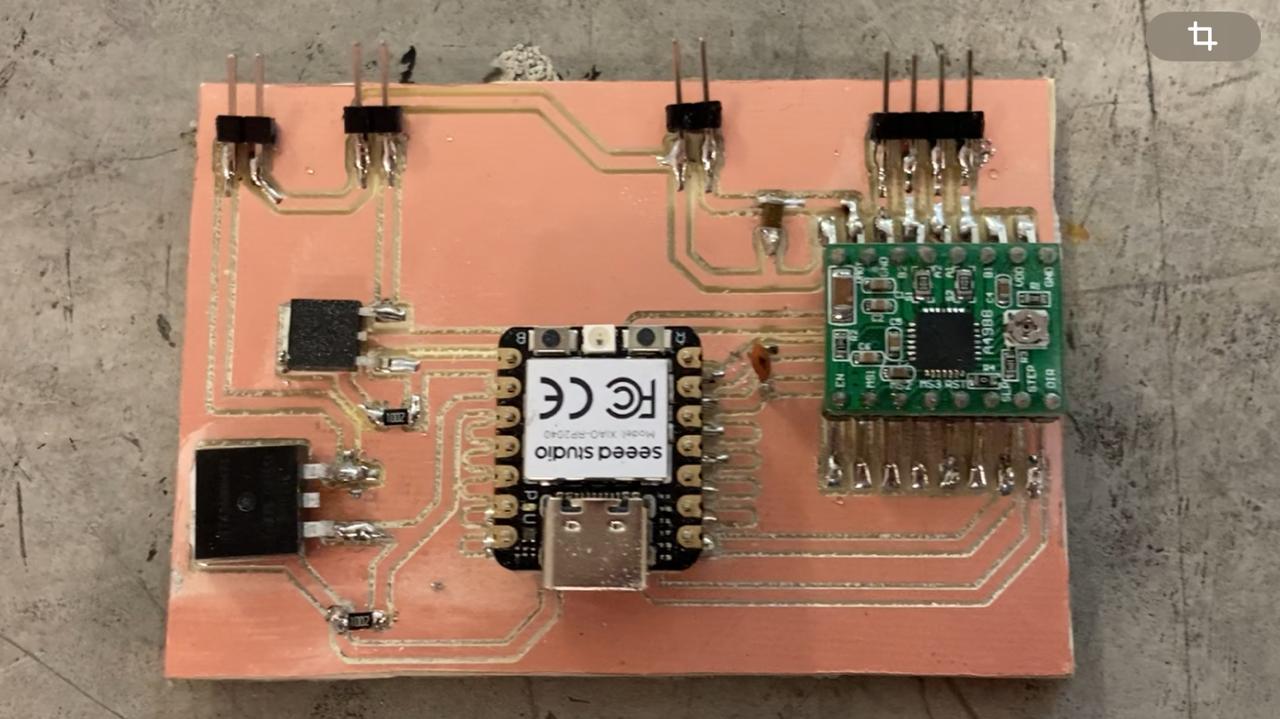
PCB Machining
As always, I used MODS to create the path as seen on Week 5 and machined it, and then soldered the superficial components.
Testing
To test the Driver and LED, I decided to use the following code that I intend to connect in the future to my interface:
#include <Arduino.h>

#define STEP_PIN 1
#define DIR_PIN 2

void setup() {
    Serial.begin(9600); //
    pinMode(STEP_PIN, OUTPUT);
    pinMode(DIR_PIN, OUTPUT);
}

void loop() {
    if (Serial.available() > 0) {
        char command = Serial.read();
        switch (command) {
            case 'L':
                Serial.println("Command received: Move motor left");
                digitalWrite(DIR_PIN, LOW);
                stepMotor(2000);  // Move motor for 2 seconds at a time
                break;
            case 'R':
                Serial.println("Command received: Move motor right");
                digitalWrite(DIR_PIN, HIGH);
                stepMotor(2000);  // Move motor for 2 seconds at a time
                break;
            default:
                Serial.println("Unknown command received");
                break;
        }
    }
}

void stepMotor(int duration) {
    unsigned long startTime = millis();
    while (millis() - startTime < duration) {
        digitalWrite(STEP_PIN, HIGH);
        delayMicroseconds(500);
        digitalWrite(STEP_PIN, LOW);
        delayMicroseconds(500);
    }
}

void toggleLED(int pin) {
    digitalWrite(pin, !digitalRead(pin));
}
Results
The motor will go left or right according to the command set on the terminal. In this example, the motor was turned 1 time to the right and 5 times to the left.
