Computer-Controlled Machining
This week, we have been presented with an exciting challenge: to create something BIG! So, without further ado, let's dive into the matter. I've been thinking over numerous concepts and eventually settled on a project that is not only functional but also speaks to my personal style. My plan is to construct a coffee table for my apartment.
However, this isn't going to be just any ordinary coffee table. It's going to be a modular coffee table. The modularity of the design ensures that it will be able to be assembled and disassembled according to my needs, making it highly adaptable and versatile.
The size of the table is another key component of my design. I want it to be large enough to accommodate a few of my favorite board games while still leaving room for a coffee mug or two, of course! In this way, it will serve not just as a piece of furniture, but also as a hub for entertainment and relaxation in my living room. So, let's embark on this journey of creation and see where it takes us!
So if I’m going to play boardgames on it, how about I create a table with the shape of a puzzle? That would allow me have a big table when I need it or some individual size tables when just having a social get together.
But before we begin, lets take a look into our FAB Lab’s group assignment and learn about our machines, how to use them and some safety advices.
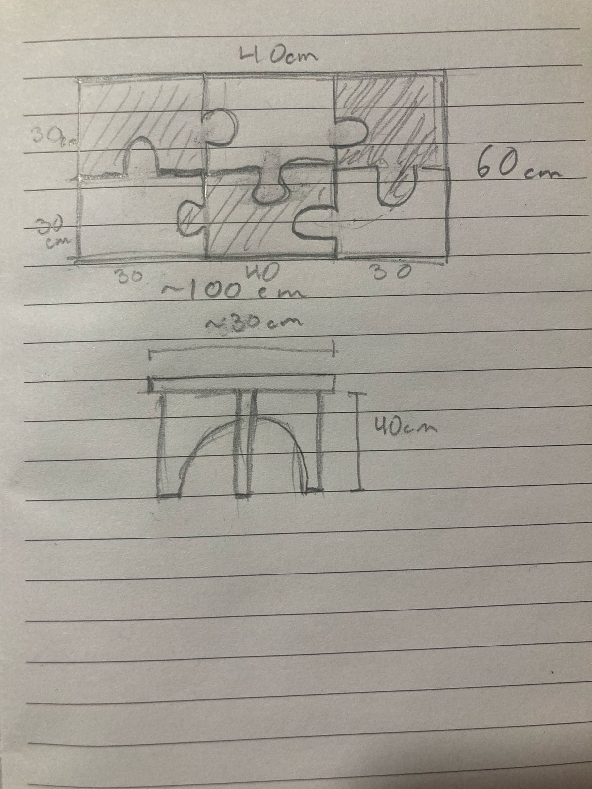
CAD
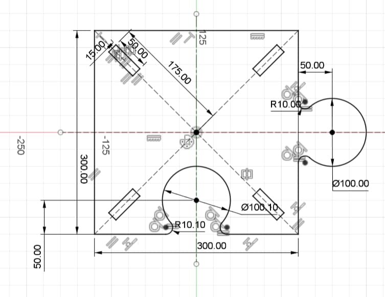
Let’s get this design into CAD. Lately I’ve been really excited to work on Fusion 360, so I created a new File and started to create my sketch. One of the most critical things would be to make sure that all pieces will get smoothly together. For this after I created this first puzzle piece where the right circle figure has a slightly smaller layout than the hole on bottom where it is supposed to fit in.
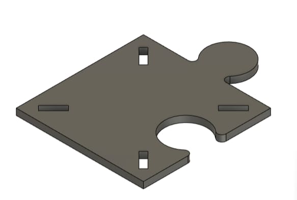
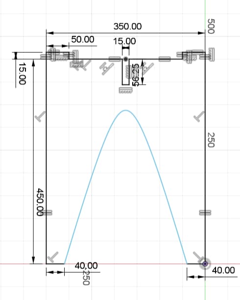
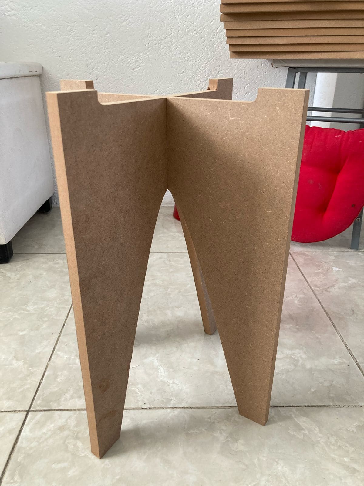
To create the legs, I wanted a design that gives stability to the table, therefore the first idea I had was to create a simple snap
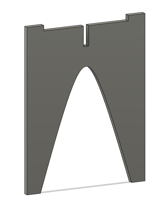
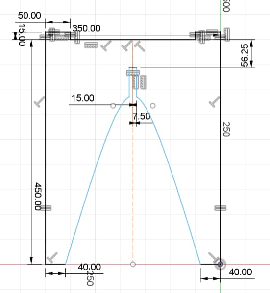
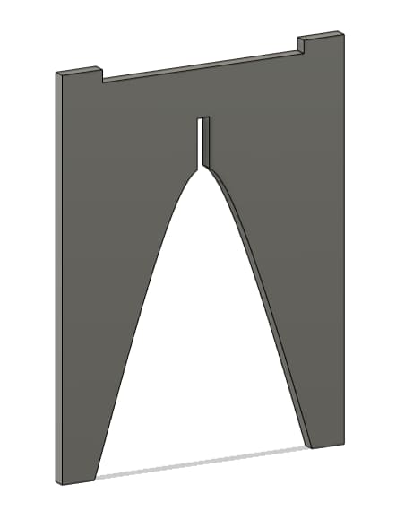
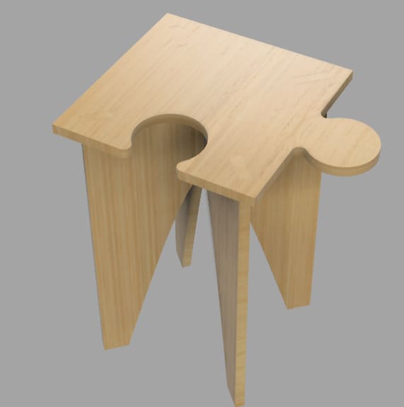
After creating each individual pieces, I created an assembly to make sure all the parts will fit together. As it can be seen the table starts to make sense so I made a render to simulate the table with a texture of bamboo. For the assignment I will use MDF of 15mm as a first step, however if I like how it looks in my Livingroom, I may change later to a finer wood like Parota or Pine wood
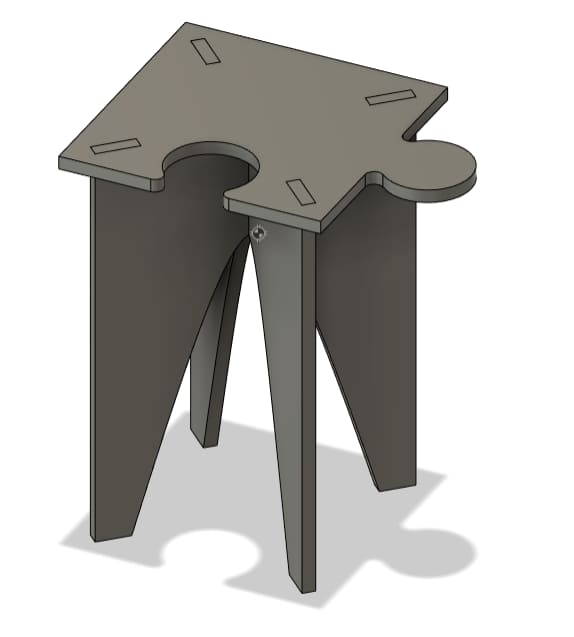
VCarve Pro 7
In order to transform our Computer-Aided Design (CAD) into a format that our router can effectively machine, we must utilize an intermediate software known as VCarve Pro 7. This software acts as a critical bridge, taking on the role of generating a viable path for our end mill. This is a similar process to what was carried out during our Electronics Production assignment. VCarve Pro 7 has the ability to take in our DXF as an input and, in return, provides us with a gcode output. This gcode contains all the necessary parameters for our project. The specifics of these parameters and their importance in the overall process will be discussed and explained in detail in the following sections.
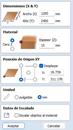
After we import the dxf to the software, we need to stablish 3 important parameters for our canvas
- Height and width of our material
- Thickness of the material
- XY origin of the machine
- Units of the design
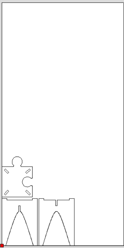
I started by importing just a single set of the corner table. However, I soon realized that I could simply employ the 'copy and paste' method to create an additional three sets of the table, which I then arranged within the confines of the sheet. The purpose of this initial stage was to maximize the use of available space and to ensure that I could fit in as many pieces as possible without causing any overlaps. Additionally, I also made the decision to import the middle puzzle piece. Unfortunately, due to lack of space on the current sheet, I found that I was missing one set of legs which I would get from some scraps of other FAB Lab students.
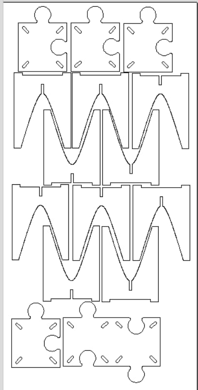
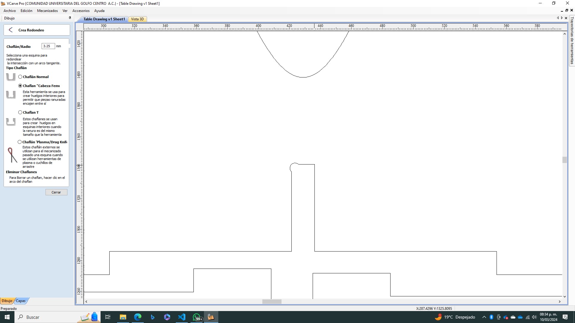
To create the path for our endmill first we need to make sure that our design is closed. Sometimes some software will not close the vertex. To do this we used the Vcarve tool. As well, we will need to add a t-bone fillet to every part where an assembly will happen. to do this, We just need to select the tool called fillet and elect the t-bone option and then select all the vertex where an assembly will occur. This process and it's importance can be seen on our group assignment and how to properly create them to ensure a perfect fit!
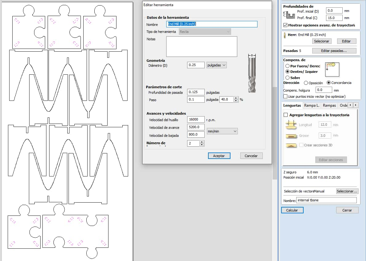
Once we have the vectorized trajectory done, we need to select the machining we want to do on our CNC router. In our case we only want to create a profile of the internal connections as they will need an internal toolpath where the endmill goes inside the vector. In this step we will also set all of our tool parameters for a endmill of 1/4 in at 16,000 rpm and a feed rate of 5,200 mm/min.
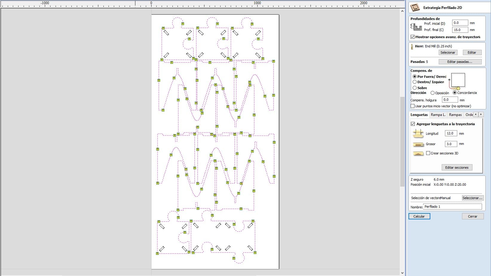
To get our external profile we will use the same parameters for our endmill, only changing the toolpath from inside to outside, making the tool have a external cut in perspective from the vector. As this pieces will move unless we secure them, we will add tabs of 12 mm long and 3 mm of thickness. This tabs will be placed automatically first at every 300 mm with a minimum of 1 and maximum of 10 per piece. How ever, I had to manually delete some of those tabs in order to have a smooth surface where the assembly will take place.
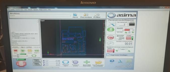
Once I had both paths calculated, all I needed to do was to export them and have the Gcode saved at a USB so I can later on transfer those Gcodes to the computer that controls the CNC Router machine. To get the machine going I only needed to set the zeros of the machine on it’s own software. I then imported my file to the hardware and get the file running.
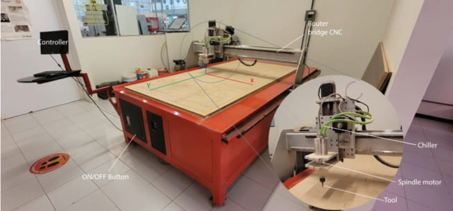
| Attribute | Details |
|---|---|
| URL | Not Given |
| Machine | Generic Made by University |
| Dimensions | 3x1.8x1.7mts |
| Motor Power | 4 HP at 24000 rpm's |
| Power Supply | 220v/2F/3.5KW |
| Material Fixtures | Nails |
Machining Process
Following this, I proceeded to set a 'Zero' within the Mach software, effectively establishing the origin point across all three dimensions - the X, Y, and Z axes. This crucial step ensured the precision of the subsequent procedures. By creating this reference point, I was able to accurately position every nail, ensuring they would be safely out of the milling path. To further enhance the precision and safety of the operation, I implemented a slight offset on the X-Y plane. This precautionary measure provided additional assurance that the milling path would remain clear, thereby preventing potential damage to the equipment or the piece being milled.
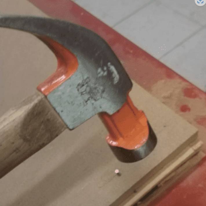
The initial step in the machining process involved securely fastening the MDF board into place. This procedure was of utmost importance to ensure the stability of the board throughout the operation of the machine. The act of securing the board helps prevent any undesirable movement that might have otherwise occurred while the machine was in use. This is a crucial step not only for the success of the machining process but also from a safety standpoint. Any uncontrolled movement of the board during operation could lead to potential mishaps or accidents, thus highlighting the importance of this step.
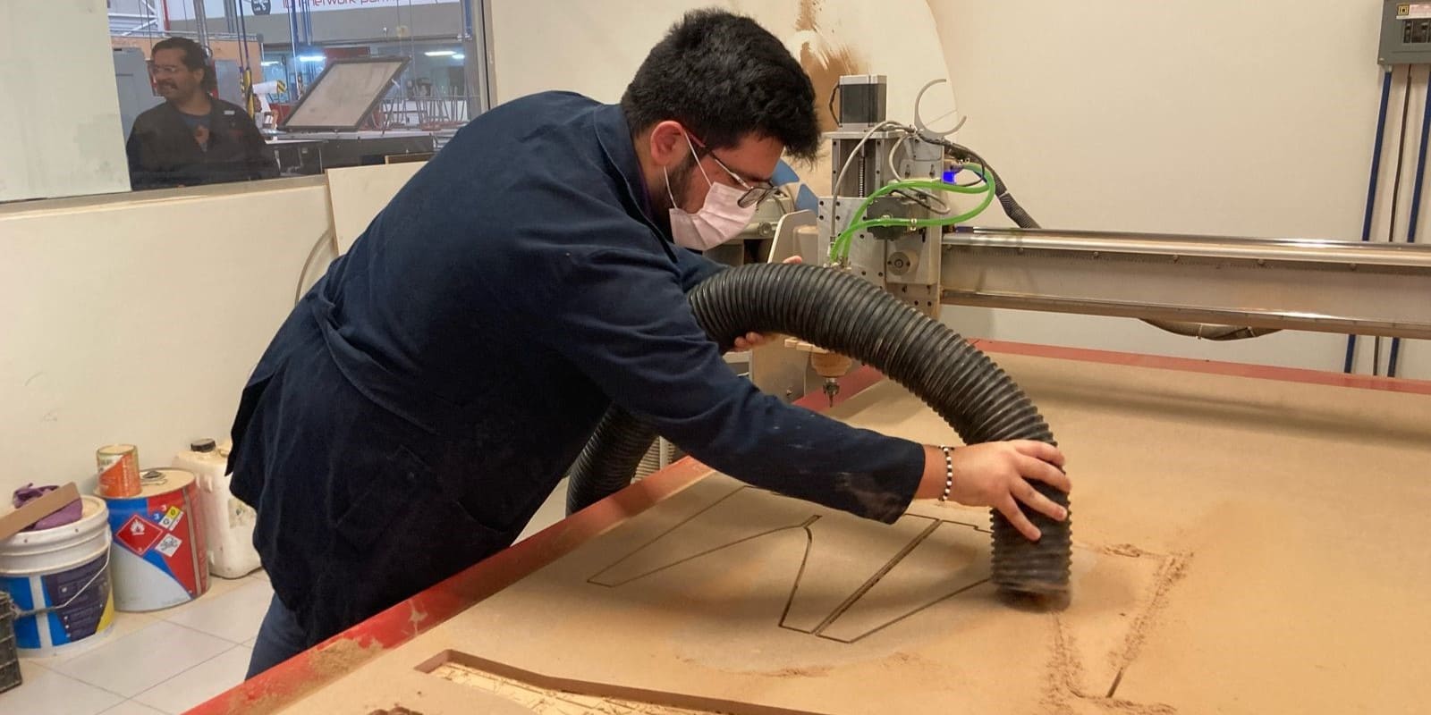
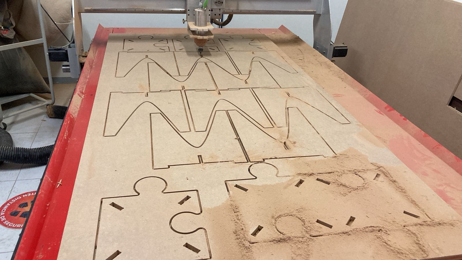
Once the fixture was securely set and the machine was perfectly calibrated to zero, it was time for the next phase of the process. All preparations had been meticulously carried out and it was time to trust in the precision and efficiency of the machine.
Assembly
To assemble I needed a rubber hammer to make sure not to damage my pieces and still get that extra kinetic energy to make my pieces get together. It was a bit of a challenge as there where many pieces but after some physical work, it was done!
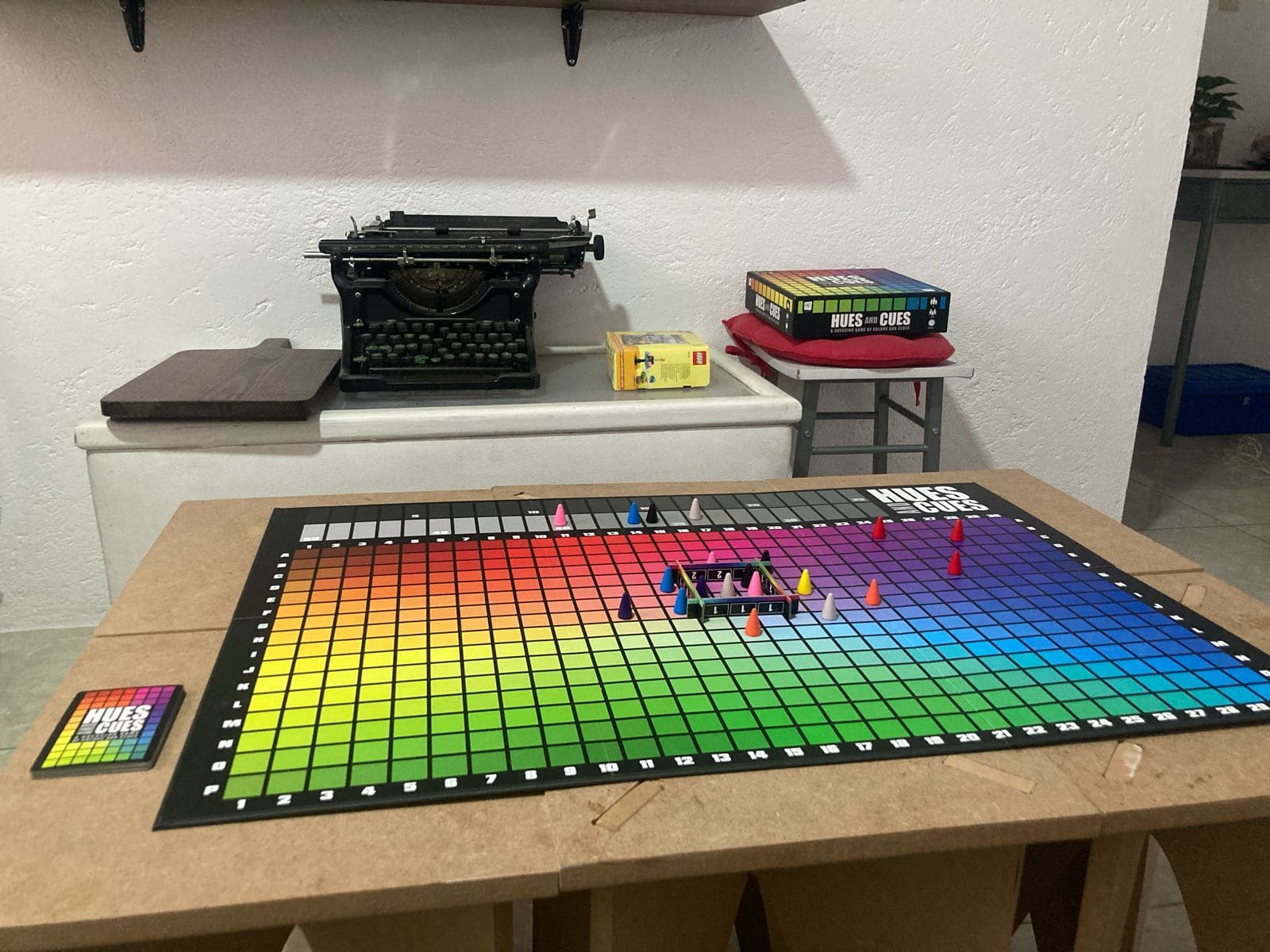
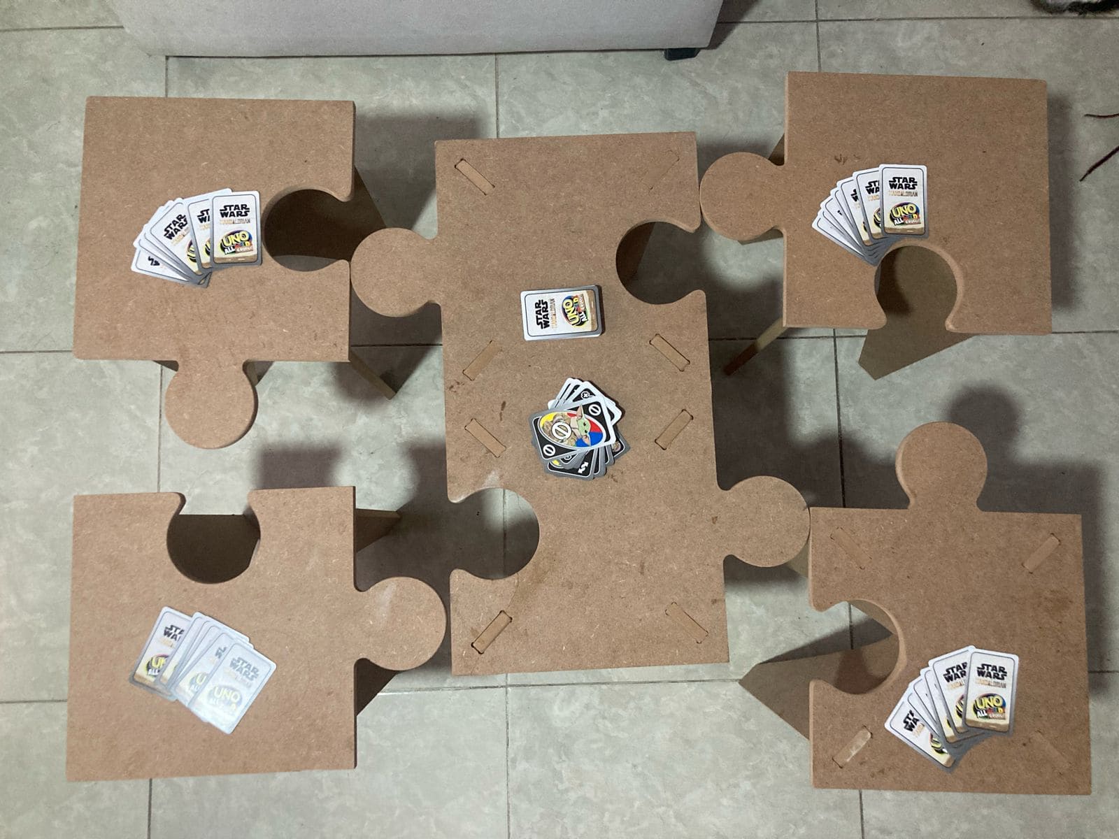
Final product
The final product is a functional 90cm * 60 cm * 45 cm table that can be assembled as a puzzle or have 5 individual pieces depending on the game that will be played.
I made the mistakes so you don´t have to…
I believe we learn more from mistakes than we do from success, how ever that doesn’t mean it won’t be time consuming and frustrating. So I will leave here all my mistakes and how I fixed them.
| Mistake | Solution |
|---|---|
| Measure twice cut once: I did gave to my design an offset so that the puzzle shape would fit, how ever I did not gave enough so the pieces were still pressured a lot | Sanding the edges…. lot´s of sanding |
| Forgot T-bones on some parts of my assembly parts. I did several versions on the Vcarve software and forgot to add critical T-bones on my final version | Had to redo the T-bone machining in a separate process without moving the pieces nor the piece-zeros to make sure the T-bones where added on the right spot. |
| Had some open figures and the “inside” machining was done as the opposite | Change the “inside machining” to “outside machining” |
| Unleveled bed: The Z-axis was off by a 1 mm at the top side which led to the piece not coming off | Had to redo the machining for that extra millimeter, having to compensate the z zero at the origin, this meant a little of the sacrifice bed being machined as well on the bottom side |

