Results: Input Devices
My exploration with input devices this week is important for my final project. Therefore, I focused on testing the soil moisture sensor and the HC-SR501 PIR sensor. To test the input devices I used the XIAO RP2040 on the Fab&Plant PCB that I made on week 8.
And I did it! I programmed the soil moisture sensor to the measures the percentage of humidity in the soil from 0% to 100%. I used this code in Arduino IDE:
//Fab Academy 2024 - Fab Lab Peru - Maria Angela Mejia
//Soil moisture sensor (analog pin) code in XIAO RP 2040 in Fab&Plant PCB

// constants
const int Moisture_signal = A0; //Analog pin A0 on the XIAO RP2040 for the soil moisture sensor signal
// variables
int value;

void setup(){
	Serial.begin(9600); // Start the serial communication
}

void loop(){
  // when the plant is watered well the sensor will read a value 380∼400

  value = analogRead(Moisture_signal);  // read analog value
  value = constrain(value,400,1023);    // keep the ranges
  value = map(value,400,1023,100,0);    // map value: 400 will be 100 and 1023 will be 0
  Serial.print("Soil humidity: ");
  Serial.print(value);
  Serial.println("%");
  delay(5000);                          // read every 5 seconds
}
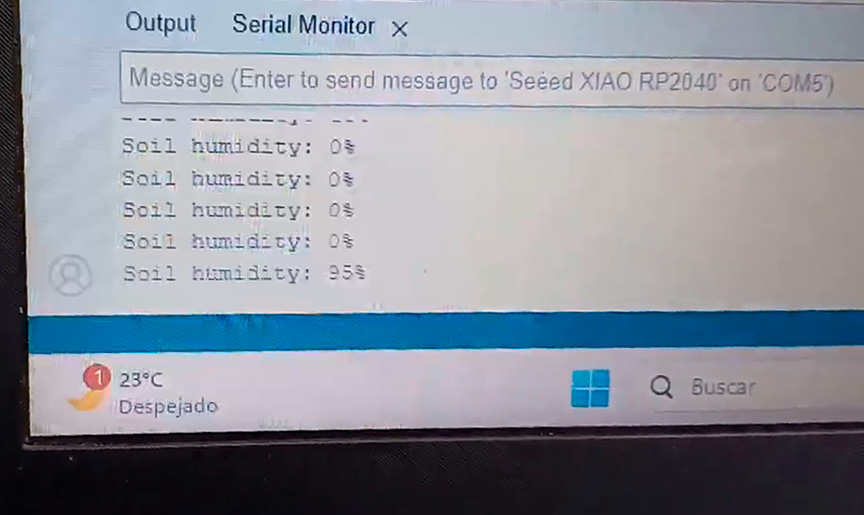
Code in Arduino IDE for programming the soil moisture sensor
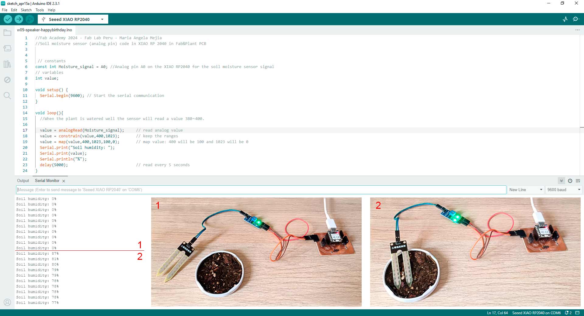
Code of soil moisture sensor well programmed
Then, I programmed the PIR sensor for measuring motion. I used this code in Arduino IDE:
//Fab Academy 2024 - Fab Lab Peru - Maria Angela Mejia
//PIR motion sensor (HC-SR501) code in XIAO RP 2040 in Fab&Plant PCB
const int pinPIR = D10;

void setup() {
  // Start serial communication
  Serial.begin(115200);
  // Configure the PIR sensor pin as input
  pinMode(pinPIR, INPUT);
}

void loop() {
  // Read the state of the PIR sensor
  int pirState = digitalRead(pinPIR);

  // If motion is detected
  if (pirState == HIGH) {
	// Print "movement" message on the serial port
	Serial.println("Movement detected");
  } else {
	// Print "off" message on the serial port
	Serial.println("No movement detected");
  }

  // Wait for a brief period before reading again
delay(2000);
}
Code in Arduino IDE for programming the PIR sensor
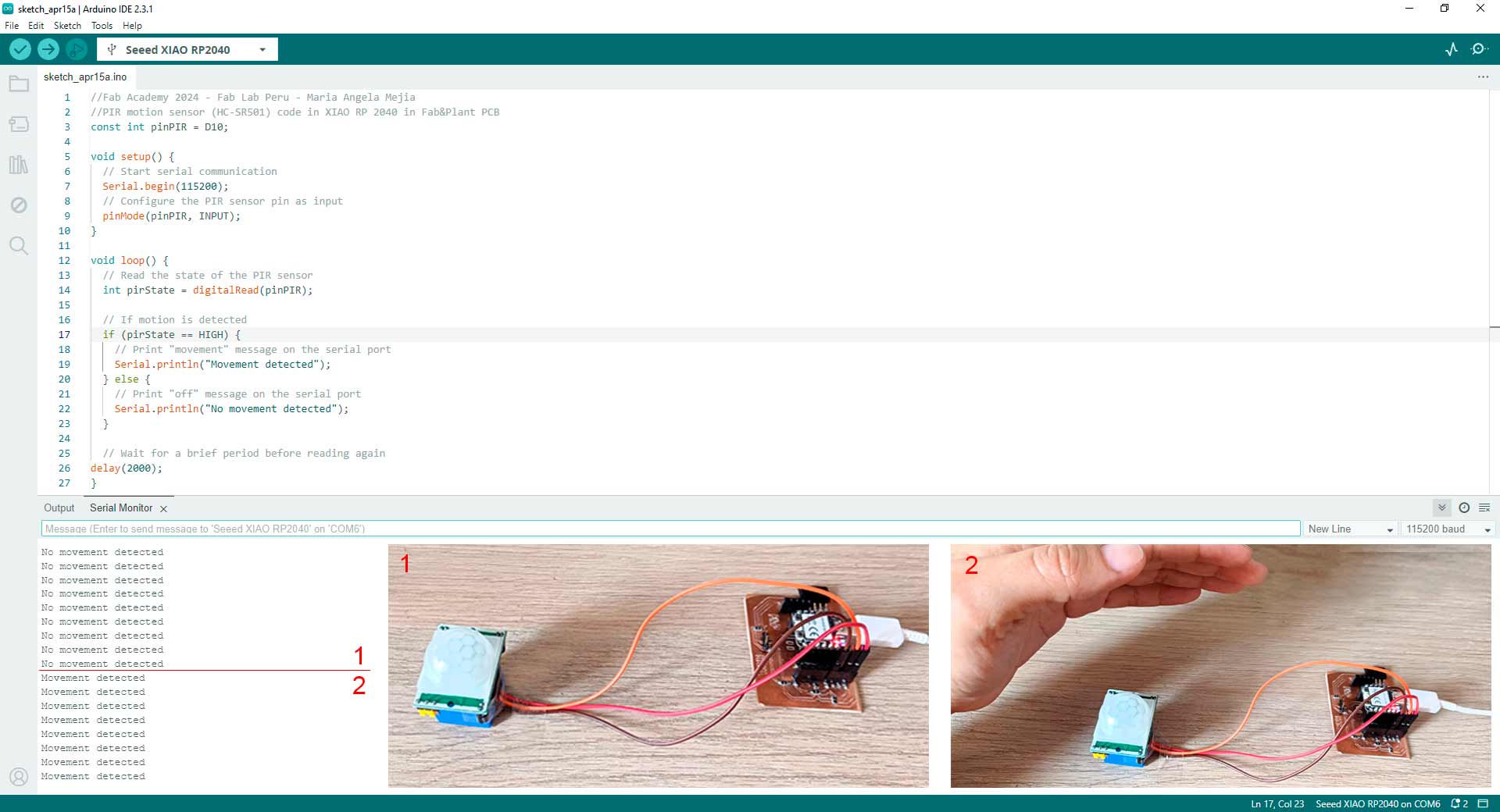
Code of PIR sensor well programmed
This week's exploration was very productive as I feel that it helped me understand how the programming and electronics of my final project will work.
Preliminary Concepts
This week I complemented what I learned during week 9 (output devices).
Glossary
- Input device: Hardware component that allows users to interact with a computer system by providing data and commands. It sends data to the computer for processing. It typically converts physical actions or signals into digital data that the computer can understand. Input devices are used to input data and commands into the computer system. Examples: keyboards, mice, touchscreens, scanners, microphones, and sensors.
- Output device: Hardware component that conveys information processed by the computer system to the user. It receives data from the computer and presents it to the user in a perceivable form. It produces the results of processed data, making it available for users to view, hear, or otherwise perceive. Examples: monitors, speakers, printers, projectors, and motors.
- Differences:
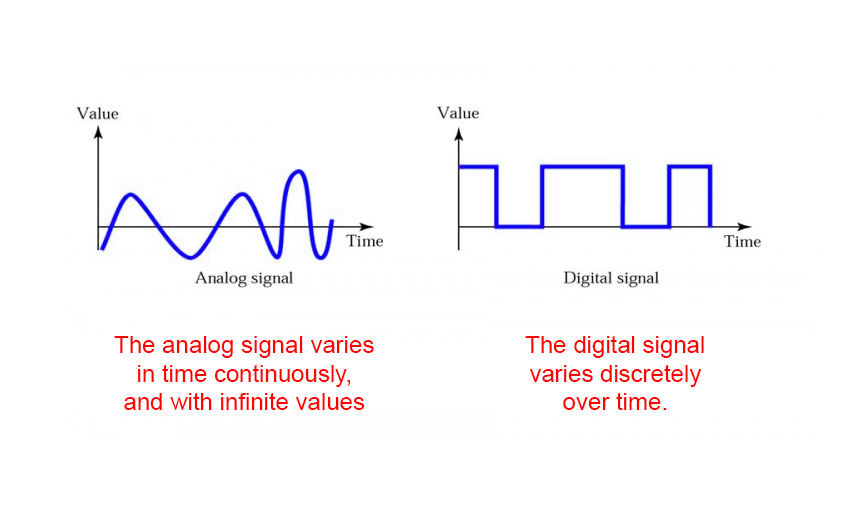
- Digital pins offer binary data, showcasing square waveforms on an oscilloscope as they transition between HIGH and LOW states, with the rise and fall times critical for signal integrity analysis; thus, they excel in capturing discrete events, like motion detection.
- Analog pins deliver a continuous range of voltage readings, translating to waveforms on an oscilloscope reflecting voltage changes over time, with waveform attributes revealing signal behavior, making them ideal for monitoring fluctuating physical parameters like light intensity, temperature, or soil moisture levels.
- With the PIR motion sensor, Fab&Plant PCB can detect human presence within its vicinity. This capability opens up possibilities for applications in my final project such as triggering actions based on human presence in an area.
- Integrating a soil moisture sensor allows Fab&Plant PCB to monitor the moisture level of the soil. This feature is useful for applications in my final project related to plant care in my module.
- Combining both sensors enables Fab&Plant PCB to provide a more comprehensive environmental monitoring solution creating a responsive and smart gardening system.
- Because my board has very thin traces, it was quite difficult when soldering. This meant that while carrying out the tests with the sensors, at times the solder would come off and I could not generate the tests correctly.
- To finish this task I thank my fellow students and tutors, especially Roberto Delgado and Ulises Gordillo for the guidance in this process, Silvana Espinoza and Hans Moncca for helping me with the use of the milling machine and valuable tips on addign sensor to my PCB.
- Fab Academy week 11 class
- Tutorial 1 of how to use a soil moisture sensor
- Tutorial 2 of how to use a soil moisture sensor
- Tutorial 1 of how to use the HC-SR501 PIR sensor
- Tutorial 2 of how to use the HC-SR501 PIR sensor
- Tutorial 1 of how to use the HC-SR04 ultrasonic sensor
- Tutorial 2 of how to use the HC-SR04 ultrasonic sensor
- Fab&Plant PCB file
- Video smaller
| Item | Input | Output |
|---|---|---|
| Purpose | Input devices are used for providing input to the computer system, such as commands, text, or raw data | Output devices are used to present the processed information or results to the user in a perceivable form |
| Function | Input devices capture or sense user input and convert it into a format that the computer can process | Output devices receive processed data from the computer and present it in a human-readable or perceivable form |
| Direction of data flow | Input devices transmit data from the external environment to the computer | Output devices receive data from the computer and present it to the user |
| Interaction | Users interact with input devices to provide instructions or input to the computer system | Output devices provide feedback or display results to users based on the processed data |
Analog vs digital signals
Group Assignment: Probe Input Device
The group assignment page is here.
What I Learned From Team Work
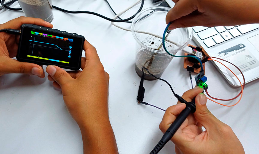
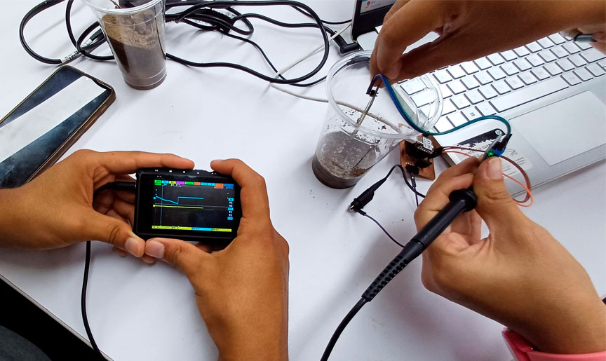
To use the oscilloscope -as a team- we went to Universidad Cientifica del Sur (UCSUR) Fab Lab which is located in the architecture faculty of the university, in Chorrillos district, in Lima, Peru.
Probing an Analog Signal
The oscilloscope is a versatile electronic instrument used to visualize and analyze the waveform of electrical signals over time. It displays the amplitude (voltage) of a signal on the vertical axis and time on the horizontal axis, allowing users to observe the shape, frequency, amplitude, and other characteristics of the signal. Oscilloscopes are commonly used in various fields, including electronics, telecommunications, physics, and engineering, for tasks such as troubleshooting circuits, measuring signal integrity, analyzing frequency response, and debugging electronic systems. Modern oscilloscopes often come with advanced features such as digital storage, multiple channels, various trigger options, and built-in signal processing capabilities.
For this task, we used the Miniware DS213 Mini Oscilloscope. For learning its usage, we followed the user manual. We used a soil moisture sensor connected to a PCB with a XIAO RP2040.
First, we probed the analog signal. We used this code in Arduino IDE:
//Fab Academy 2024 - Fab Lab Peru
//Soil moisture sensor (analog pin) code in XIAO RP 2040

// constants
const int Moisture_signal = A0; //Analog pin A0 on the XIAO RP2040 for the soil moisture sensor signal
// variables
int value;

void setup(){
  Serial.begin(9600); // Start the serial communication
}

void loop(){
  // when the plant is watered well the sensor will read a value 380∼400

  value = analogRead(Moisture_signal);     // read analog value
  value = constrain(value,400,1023);       // keep the ranges
  value = map(value,400,1023,100,0);       // map value: 400 will be 100 and 1023 will be 0
  Serial.print("Soil humidity: ");
  Serial.print(value);
  Serial.println("%");
  delay(5000);                             // read every 5 seconds
}
Code in Arduino IDE for programming analog pin in soil moisture sensor connected to XIAO RP2040
We place the soil moisture sensor in the air and get this:
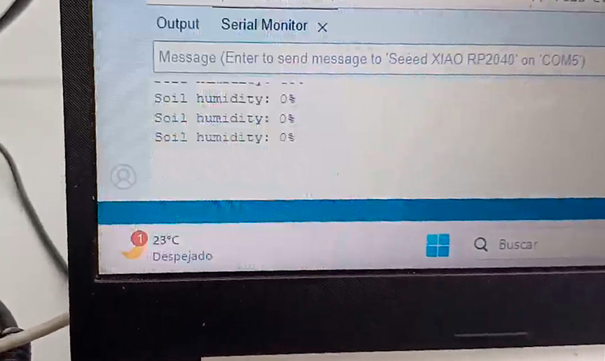
Wave going down when soil moisture sensor is in the air
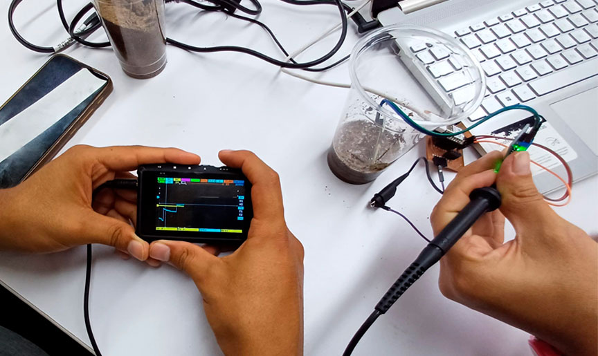
Then, we place the soil moisture sensor in wet soil and get this:
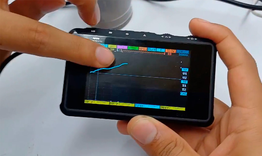
Wave going up when soil moisture sensor is in wet soil
Probing a Digital Signal
Later, we probed the digital signal. We used this code in Arduino IDE:
//Fab Academy 2024 - Fab Lab Peru
//Soil moisture sensor (digital pin) code in XIAO RP 2040

 // constants
const int Moisture__dig_signal = D0;    //Digital pin D0 on the XIAO RP2040 for the soil moisture sensor signal
int Sensor_State = 1;
void setup() {
  pinMode(Moisture__dig_signal, INPUT); //Step pin as input
  Serial.begin(9600);                   // Start the serial communication
}

void loop() {
  Serial.print("Soil Moisture Level: ");
  Sensor_State = digitalRead(Moisture__dig_signal);
  if (Sensor_State == 0) {
	Serial.println("Wet");
  }
  else {
	Serial.println("Dry");
  }
  delay(5000);                          //Read every 5 seconds
}
Code in Arduino IDE for programming digital pin in soil moisture sensor connected to XIAO RP2040
We place the soil moisture sensor in the air and get this:
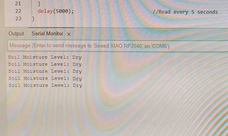
Binary signal when soil moisture sensor is in the air
Then, we place the soil moisture sensor in wet soil and get this:
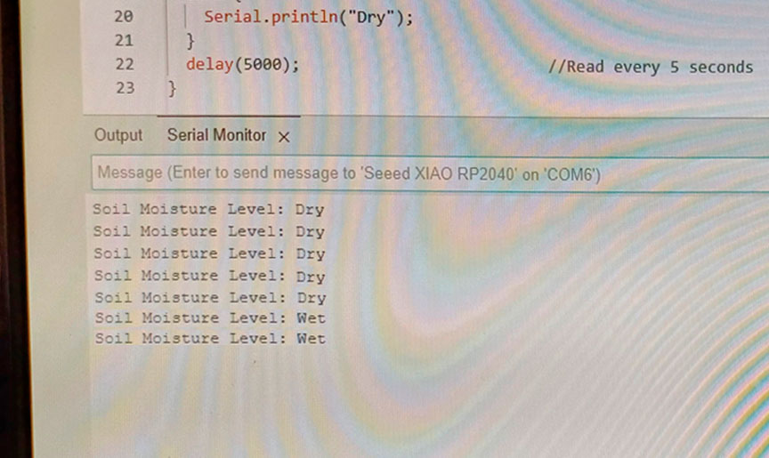
Binary signal when soil moisture sensor is in wet soil
Conclusions:
The team's collaborative approach effectively utilized digital and analog pins, enabling comprehensive sensor data monitoring and analysis for optimized system performance and decision-making.
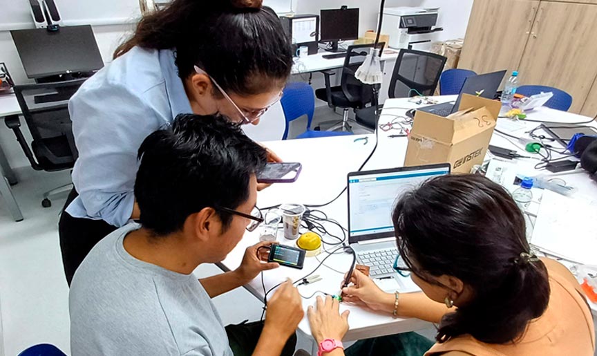
Team work at UCSUR Fab Lab
Individual Assignment: Adding Sensors to my PCB
My exploration with input devices this week is important for my final project. Therefore, I focused on testing the soil moisture sensor and the HC-SR501 PIR sensor. To test the input devices I used the XIAO RP2040 on the Fab&Plant PCB that I made on week 8.
Soil Moisture Sensor
A soil moisture sensor enables the measurement of soil moisture levels. This is especially useful for precisely determining the watering needs of plants or evaluating the rate of water drainage in a particular area. It has two main components: soil probe and a sensor circuit board. The soil probe is the component that comes into contact with the soil to evaluate its water level. Meanwhile, the sensor circuit board processes the signal from the soil probe and sends it out through the analog output pin. Additionally, the circuit board produces a digital output, which can be either HIGH or LOW based on the setting of the potentiometer.
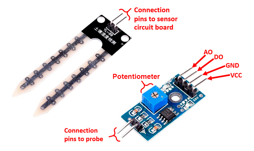
Soil moisture sensor
I connected the soil moisture sensor and programmed it with XIAO RP2040 microcontroller in Fab&Plant PCB. I used this code in Arduino IDE:
//Fab Academy 2024 - Fab Lab Peru - Maria Angela Mejia
//Soil moisture sensor (analog pin) code in XIAO RP 2040 in Fab&Plant PCB

// constants
const int Moisture_signal = A0; //Analog pin A0 on the XIAO RP2040 for the soil moisture sensor signal
// variables
int value;

void setup(){
  Serial.begin(9600); // Start the serial communication
}

void loop(){
  // when the plant is watered well the sensor will read a value 380∼400

  value = analogRead(Moisture_signal);     // read analog value
  value = constrain(value,400,1023);       // keep the ranges
  value = map(value,400,1023,100,0);       // map value: 400 will be 100 and 1023 will be 0
  Serial.print("Soil humidity: ");
  Serial.print(value);
  Serial.println("%");
  delay(5000);                             // read every 5 seconds
}
Code in Arduino IDE for programming soil moisture sensor in Fab&Plant PCB
Code well programmed
PIR Sensor
The HC-SR501 PIR sensor, a passive infrared sensor, detects the presence of a body by sensing the infrared radiation within its range. When ther is no object in front of the sensor except the background, it remains in a stable state. However, when an object moves in front of it, the infrared radiation detected by the sensor alters. Once the object passes, it returns to its initial state. This alteration is identified, causing the sensor to emit a signal indicating the detection of a body. The HC-SR501 PIR sensor has three pins: GND, Out, and VCC. GND: connected to the main circuit ground. VCC: a typical voltage for this sensor is 5V. Out: it will output 3.3V when motion is detected, and 0V when there is no motion. This sensor has two settings that can be adjusted by turning the screws show on the image to the right: sensitivity and time delay. Sensitivity will define the range/distance over which the sensor will be “looking” for motion. The lowest setting would be approximately 10ft/3meters and the highest setting would be roughly 23ft/7meters. Time delay is how long the sensor will provide an output of 3.3V after the motion has been detected. This will range from 3 seconds, to 5 minutes.
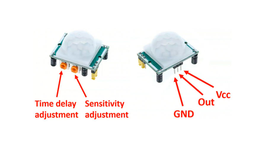
PIR sensor
I connected the PIR sensor and programmed it with XIAO RP2040 microcontroller in Fab&Plant PCB. I used this code in Arduino IDE:
//Fab Academy 2024 - Fab Lab Peru - Maria Angela Mejia
//PIR motion sensor (HC-SR501) code in XIAO RP 2040 in Fab&Plant PCB
const int pinPIR = D10;

void setup() {
  // Start serial communication
  Serial.begin(115200);
  // Configure the PIR sensor pin as input
  pinMode(pinPIR, INPUT);
}

void loop() {
  // Read the state of the PIR sensor
  int pirState = digitalRead(pinPIR);

  // If motion is detected
  if (pirState == HIGH) {
	// Print "movement" message on the serial port
	Serial.println("Movement detected");
  } else {
	// Print "off" message on the serial port
	Serial.println("No movement detected");
  }

  // Wait for a brief period before reading again
delay(2000);
}
Code in Arduino IDE for programming PIR sensor in Fab&Plant PCB
Code well programmed
The task for this week connects with what I learned in week 9, so I can understand better how the electronics will work on my final project.