✂️Week 3: Computer Controlled Cutting
Project Heros
Laser cut kit:
Vinyl cut stickers:
Group Assignment
Here is the group assignment for this week. It was a great experience and a helpful tool learning how to dial in some optimal laser cutting settings for a given material. It was quite insightful to see how much material the laser removes, I thought it would of been far smaller. On the flip side I was amazed at how it can engrave with such a thin laser, the level of precision at that speed is incredible.
Parametric Modelling
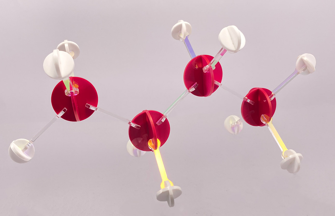
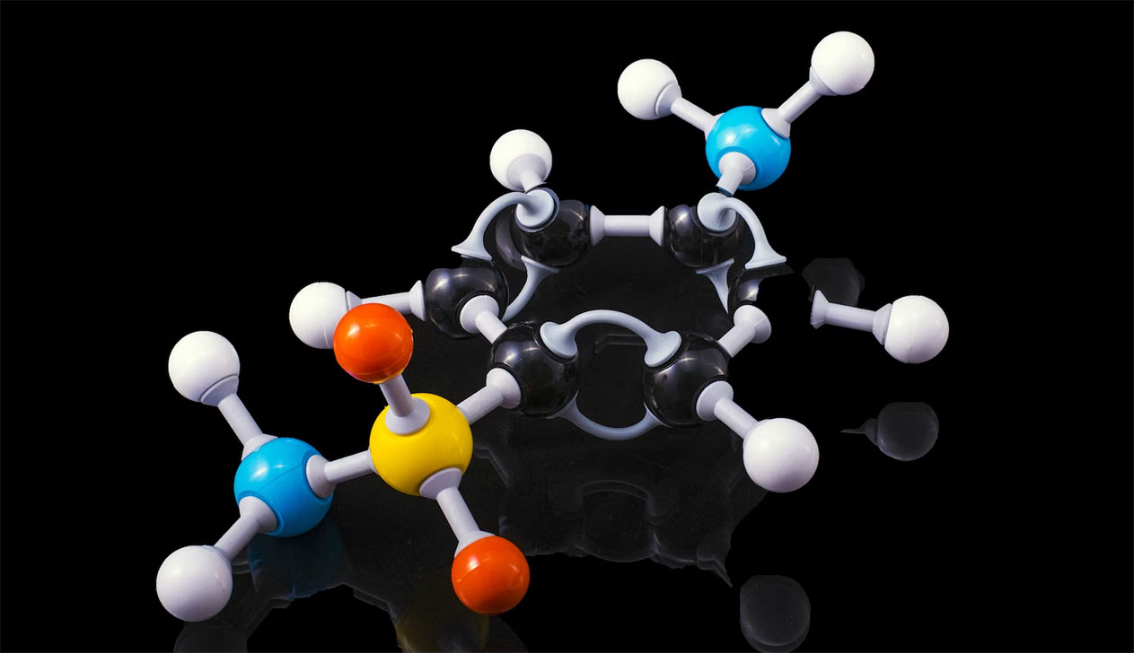
This week I want to continue using onshape for our parametric laser cut kit as I'm such a fan of having an online CAD package. This week I will be attempting to create a laser cut version of a molecule building kit (like the image below). I have always loved these kits, but they have tended to be on the pricier side, and so this is a good opportunity to investigate a cheaper laser cut alternative. We will be starting with just carbon and hydrogen atoms to make some hydrocarbons.
Assembling Atoms
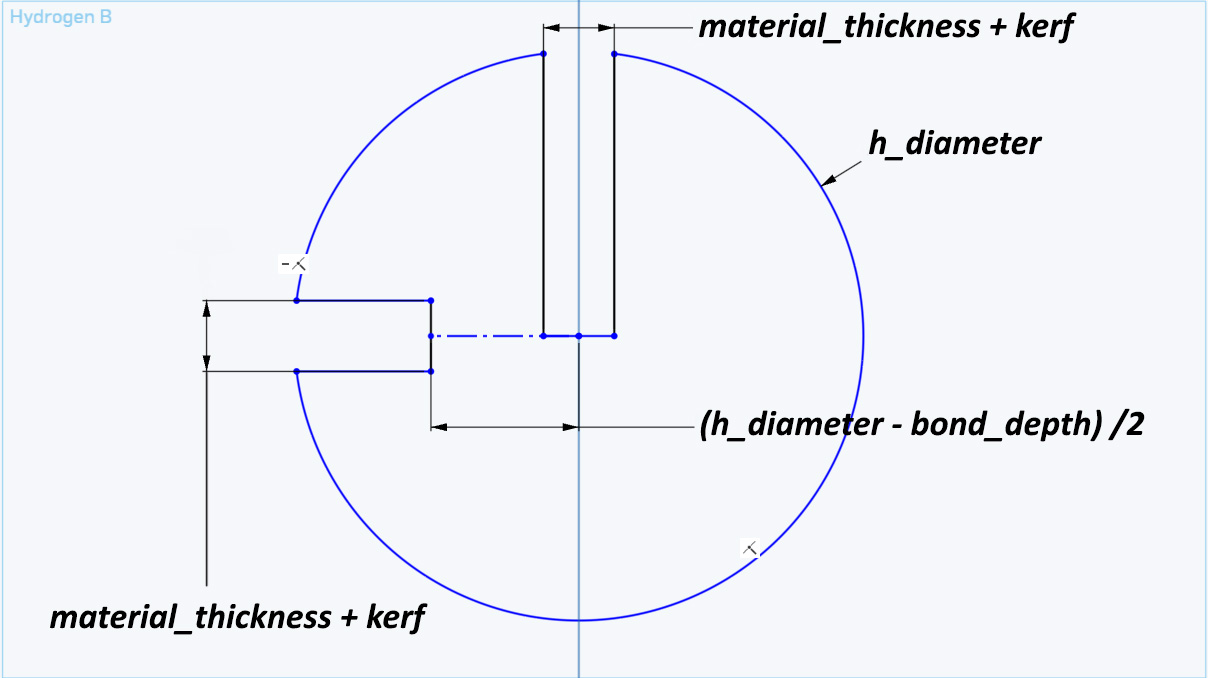
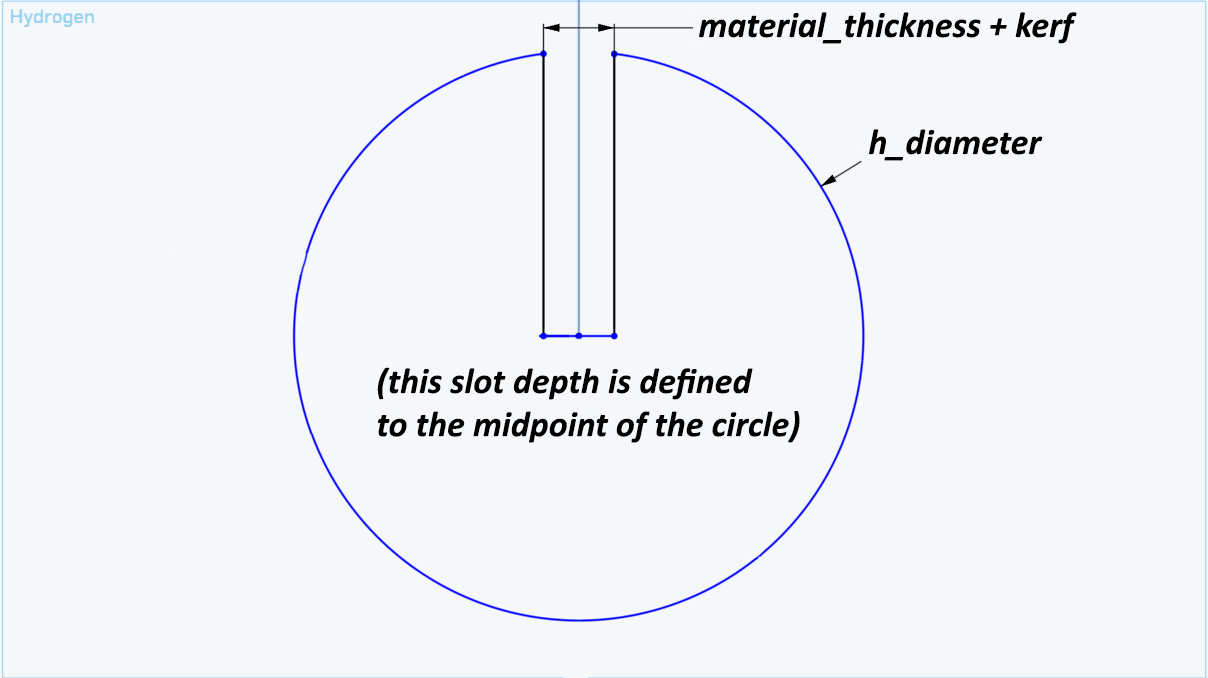
The atoms themselves will just be 2 discs slotted together to create something resembling a sphere. To do so I created a sketch in onshape and drew out the design to be laser cut. I extensively used the variables feature in onshape to define dimensions and angles of my sketches. First lets take a loot at the hydrogen. Using variables for material thickness, kerf and bond depth (the total length of the joint that the bonds will have with atoms), I defined all the slots in the atom. The large slot is for 2 discs to be put together with (the depth of it is defined to the centre of the circle), and the shallower slot is for the atomic bond joint:
Then another hydrogen disk was modelled without a bond slot as hydrogen will only has 1 bond.
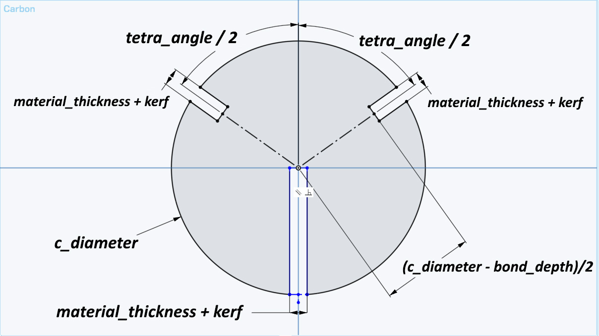
Then the same process was used to model the carbon atom. This one can fortunately use the same disc twice. Each disc will have 2 slots for bonds, and the slot to join the discs together. This time the angle between the 2 bonds needed to be defined, and was done so with the variable tetra_angle and aligned to the centre vertical plane.
Building Bonds
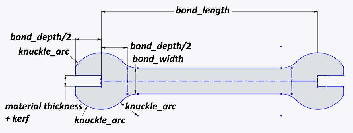
The final thing to model is the bond to hold all these together. This would take the shape of a dogbone/open-ended spanner. The new variables used in this, are bond_length and bond_width to define the rod that connects the bonds, as well as knuckle_arc to define the curves used in the knuckle section. The knuckle where the bond meets the atoms was rounded with arcs to help ease any stress points.
At this point we now have a fully parametric model with everything defined by either a variable or a scalar. From the variables window, ever aspect of these sketches can be scaled. Throughout uni and my personal projects, nearly all of my designs have been parametric, but haven't used variables to this degree and so it was a great learning excercise as I will incorporate variables into my workflow more in future projects, especially with projects that might require trial and error like in the slot thicknesses of these laser cut pieces.
LASER Cutting
This was actually the first time I have ever laser cut something (and not getting someone else to do it), so it was a great learning experience and a good change of pace from just 3d printing everything.
I laser cut my kit from acryclic as I wanted clear acrylic for the joints (it ended up having a nice slight irradescence to it), and white acrylic for hydrogen, and a magenta for the carbon.
To start, we found the kerf required like in the group assignment, with a few test prints to make sure that my design was correct. This was mighty helpful as I had a slot in the wrong position on hydrogen-a and it wouldnt connect to a bond correctly.
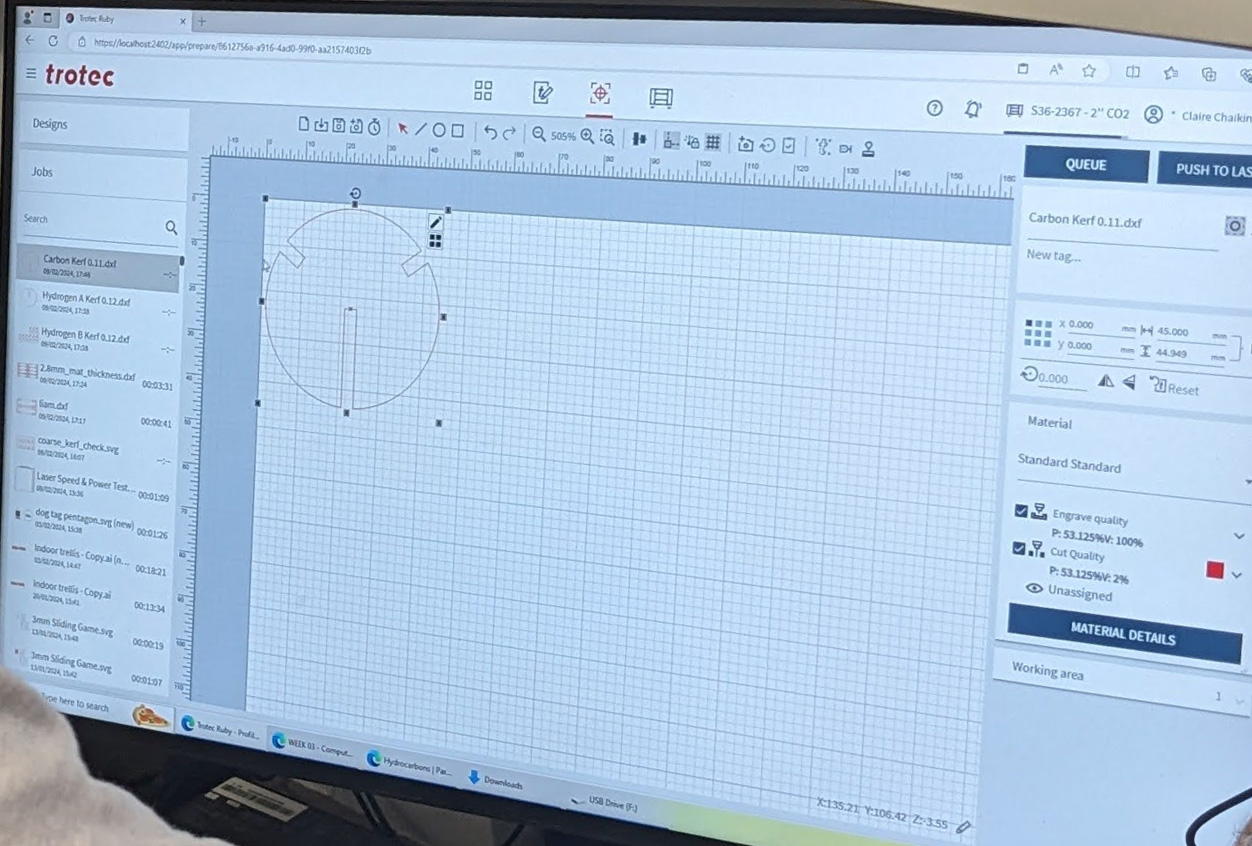
The settings I used on the Trotec Speedy 360 were:
Speed: 40%
Power: 50%
Hz: 1000
Kerf: 3.1 mm (for 3 mm acrylic)
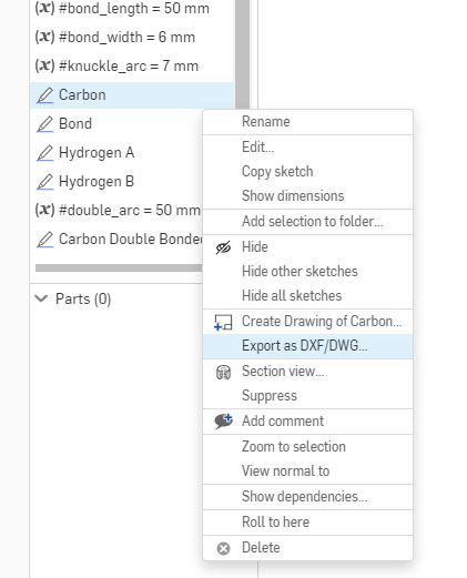
Then the onshape sketch was modified to use this kerf, and it was exported as a DXF.
Then the DXF file was imported into Ruby (Trotec's cutting software) and scaled up to the correct size as DXF is dimensionless and Ruby was importing it with the wrong units. I printed one
And I printed a batch of hydrogen-a and hydrogen-b which fit together nicely.
Next the same process was repeated to print out an army of magenta carbon atoms.
However, these were too loose. I initially thought it was how I was importing and scaling the carbon disc, but it turns out that the magenta acrylic sheet was thinner and from a different supplier. After dropping the total slot width from 3.1 to 2.94 mm, the carbon atoms slotted together nicely. A single test print here would of saved a nice square foot of acrylic :(
Then the same process was repeated in cutting the bonds (but with a quick test print first, the lab's digital calipers had run out of battery so we couldn't accurately gauge the acryclics thickness).
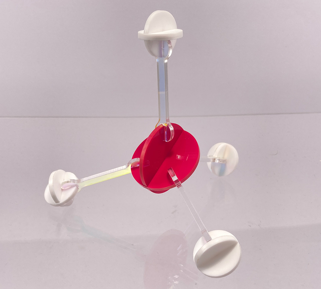
Now all of the pieces can be slotted together to build some alkanes! How about methane?
Ethane?
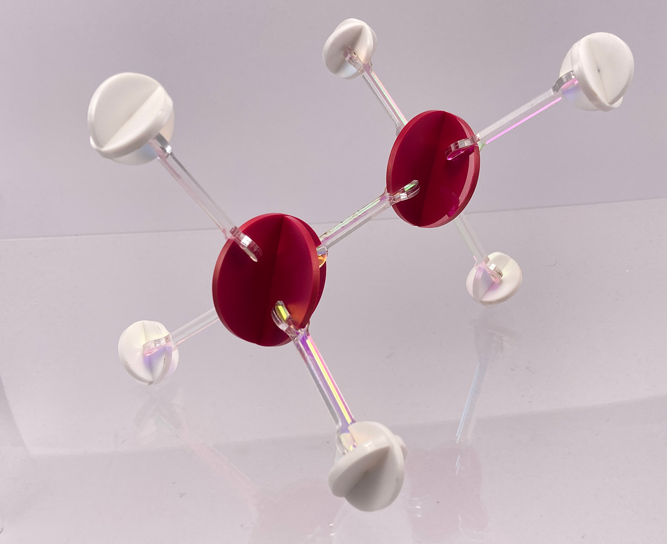
And the biggest I could build with what I had cut is butane.
Vinyl Cutting
For vinyl cutting, we will be making stickers by first printing on some printable vinyl sheet, then cutting it out with the Roland CAMM-1 GS24. This process involves having a design to print on the vinyl, and a vector for the Roland to make a cut with.
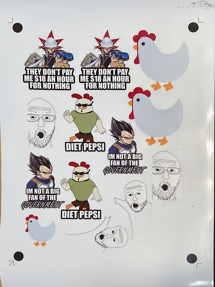
The first step was to find some stickers to print, me and some mates together got together to produce some stickers in photoshop and added text to images as well as a solid white outer glow to the whole thing. These are the images and there original sources:


These images are jpegs for compression sakes, but the originals are pngs. It should be easy to just remove the black background.
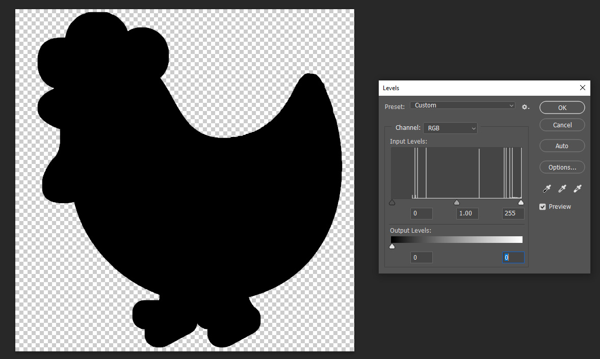
The next step is to create a vector line for the cut to be made along. I found quite a lot of difficulty in automatically generating a vector based on the png, as using the image trace tool in illustrator would produce an outline of the image that became entangled with the detail of the image. To rectify this, I created a solid black version of each PNG. For each of these images, in Photoshop I opened the levels tool and changed the output levels to only black which gave us what we needed.
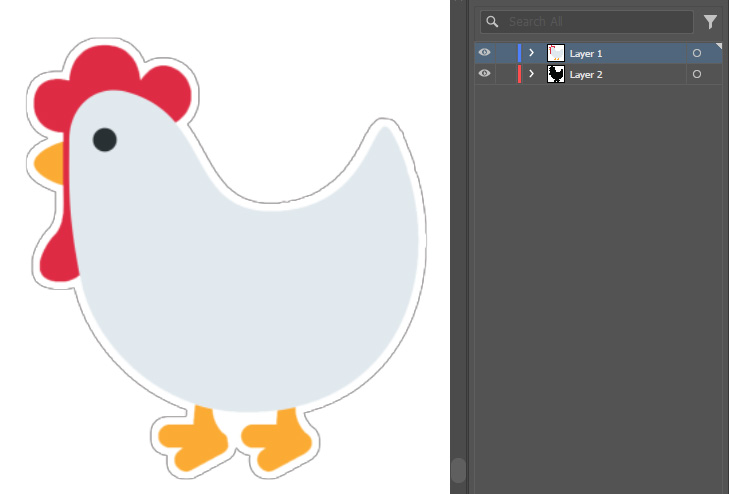
Then in illustrator, I imported the regular png into 1 layer, then the silhouette into a second layer, then aligned them to be the same size and position as each other.
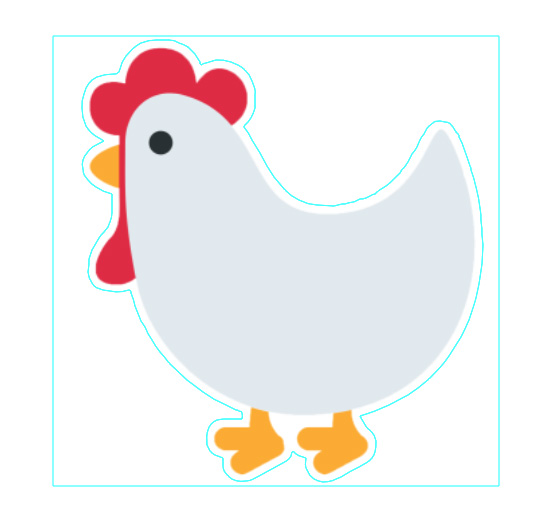
Then I ran image trace on the solhouette image, and it produced a nice vector for the sticker to be cut along. It also does also create an outter box vector, but that can be deleted by ungrouping the vectors, then deleting the outter box.
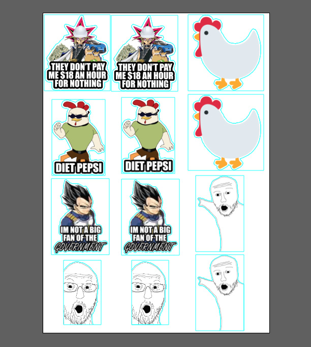
Repeat this on all images, and arrange them on the sheet, note that the Roland will have 4 outter black circles that indicate the maximum cutting area of the machine, all stickers should be inside of it, and a preview will be available in the coming steps.
To start, select the layer with the full colour images, and print it off (we used A4 high gloss printable vinyl sheets). Now we will need to pass it through the Roland. Ensure that the rollers are in the marked white zones and then insert the printed sheet into the rollers and use the lever on the left to clamp it in place. Once it is inserted, use the arrow keys to move the cutting head over the lower left black circle.
Then in illustrator, print the vector layer to the cutting machine, this will open up the CutStudio. If all the vectors look good and are within theblack cutting dots, hit cutting at the top, and click ok in the cut window.
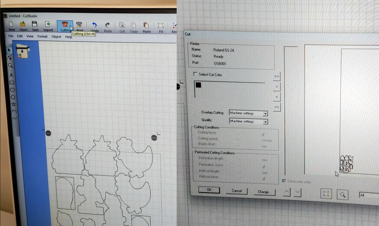
The Roland will then use the black guiding circles to find its home, then cut according to the vector layer, and voilla! We now have some nicely cut stickers.
Files
Hydrogen A
Hydrogen B
Carbon
Bond
Link to onshape project
Onshape STEP file