✂️Week 3: Computer Controlled Cutting
Model and Software
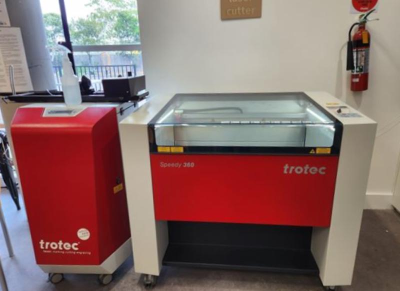
We are using Trotec Speedy 360, its an 80 Watt CO2 laser cutter, and has a bed size of 810 mm x 500 mm. We are using Trotec Ruby to print with it. This page documents the process of dialing in settings for 3mm ply wood.
Focus
The focus needs to be set to ensure that the material is the correct distance from the laser. The software will then use this set point to automatically adjust the focus to either cut or engrave. The 360 has a manual and automatic method of setting the focus.
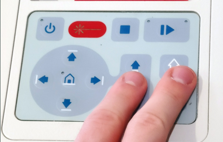
The automatic way is super easy, just turn on the machine, then hit shift and up.
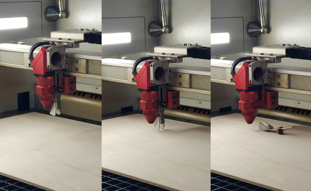
The manual way requires the focus setting bit which is specific to each laser and lens. The 3 panels below show the process of using it. First place the bit into the laser head, then lower the bed until the the material makes contact with the bed and knocks the bed off, very low-tech and cool.
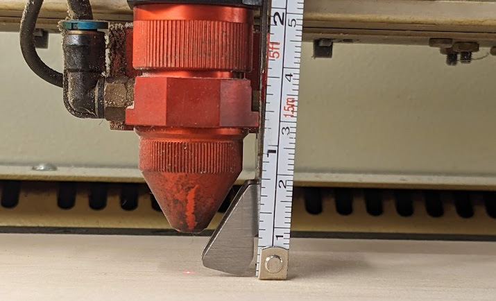
We measured the optimal focus length to be about 9 mm.
Speed and Power
We will be cutting a matrix of varying power and speeds of the laser to see which combination is optimal for this material. Start by opening Ruby, heading to the design tab, and importing the DXF in. From here you can edit anything you need in the design before it is cut. In this screen we will select a square and assign a layer to it. Each layer can be assigned a different power and speed, and this is what we will be using to conduct our test. Select 10 squares in a column and assign a layer to each of them. Then set each layer to 10% speed (in our software it needed to be a decimal? very weird) and increase the power from 10% to 100%. ONLY cut these 10 layers.
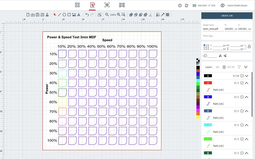
Once they have finished, select the 10 squares in the column besides it (or you can copy over the last column), and assign them now to 20% speed with power increasing from 10% to 100%. Then continue this pattern and cut each column in increasing speed until all 100 squares are cut. You will now have a grid of squares ranging from low to full speed and power.
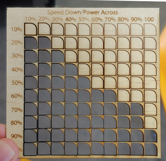
From this you can gauge what combination of power and speed are suitable by seeing which squares were cut cleanly from the material. We chose settings of 60% speed and power as it wasn't pushing the laser or the gantry too hard and gave a reasonable job time. Later though we had to bump it up to 65% power as some of our cuts were still being held on by splinters on the rear. We chalked this up to the inconsistencies in plywood, but this test gave us a good ballpark to start in then later refine.
Kerf and Fit
The kerf is the material that the laser cutter removes as it makes the cut. In combination wit the desired fit, these are what will determine the spacing needed in our CAD design for parts to slot together nicely. We used this fantastic kerf test generator to create a file that generates a range of cuts from 2.8 mm to 3.2 mm in 0.05 mm increments. This part was then cut on the machine and after testing by slotting the test pieces together, we found that for our 3 mm plywood, a slot of 2.8 mm will provide a fit that isn't too tight, but is tight enough to not easily come undone.
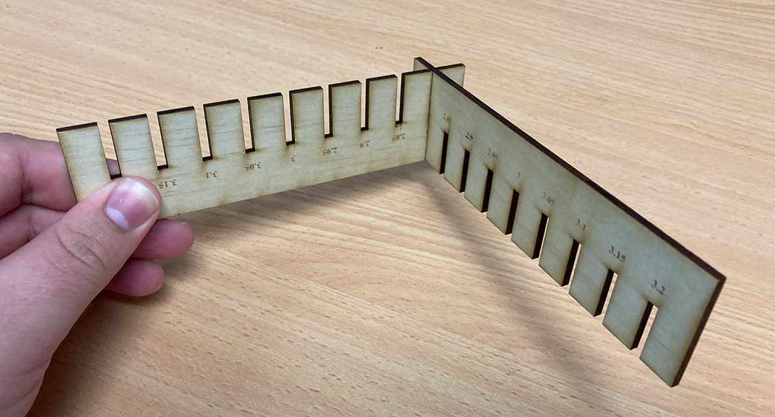
We could of used this as a starting point to go into smaller increments of kerf, but we found that 2.80 mm on the dot was already a good fit.
Final Results
From our testing we characterise that the best cutting for our 3mm plywood is:
Speed: 60%
Power: 65%
Kerf: 2.8 mm
Lab Safety
From this weeks lab induction, we also walked away with these commandments of the laser cutter
- Only use the laser cutter if you are inducted
- DO NOT leave the laser cutter unattended, even when getting a latte
- Always ensure the lid is closed when cutting
- Avoid eye contact if it hurts to look at the machine
- Keep the bed clean and free of debris
- DO NOT cut PVC, it will produce chlorine gas
- Only cut approved materials