🧊Week 2: CAD
Project Heros
Entire project 3d modelled in Onshape:
Part of project (vinyl decals to be applied) modelled in Photopea and Illustrator
3D Modelling
I have been using CAD for the last 6 years for both university assignments and personal projects. I have extensive experience with Creo Parametric and Fusion 360, but for this course I will most likely be utilising Onshape, a fantastic broswer-based program. I am not a fan of Creo, and also not a fan of Fusion 360's increasingly restrictive nature for free and student users. Onshape isn't as capable as the others, but in the realm of maker projects, these limitations aren't even an issue.
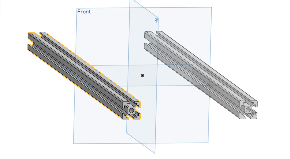
I will be attempting to model the chassis of my project to get an idea of the assemblies and parts needed. To start, we will model the 2020 aluminium extrusion that I will be using as a part of the main chassis. To do this I sketched the profile of it using the line tool, and the dimension tool to set line lengths and angles. I also used the sketch round tool to achieve the rounded edges.
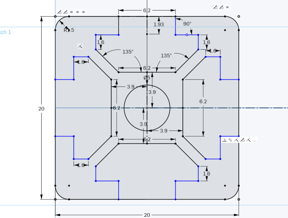
Onshape has a parts studio to model pieces in and an assembly studio to put things together with joints. I like to model most of my assembly in the parts studio as having the other pieces on hand makes it easy to model reliant pieces. That is why I placed the centre of this 2020 sketch a set distance from the centre as well,
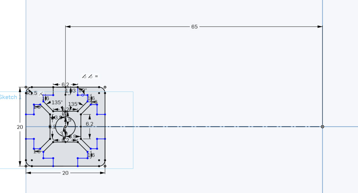
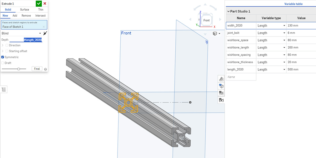
Then using the extrusion tool, I extruded the 2020 out symetrically. The extrusion length and many other important dimensions (like the distance between the centre of the 2020 extrusion sketch and centre plane), are stored in variables to allow for easy modification.
I use the mirror tool to produce another 2020 extrusion an equal distance away form the centre plane on the other side.
Using the same line and dimension tools I sketched then extruded this face. It kisses the centre plane again as I will be mirroring it.
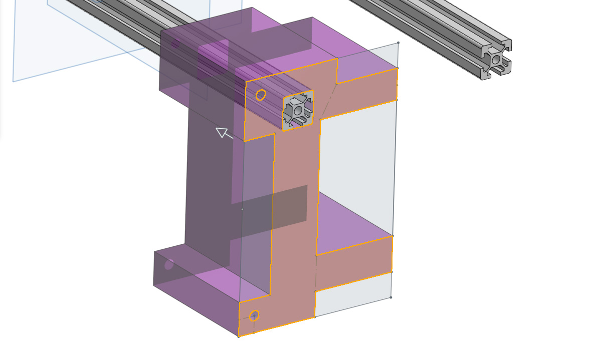
Then using the chamfer tool, I cut off some of those hard edges to make it a little more visually appealing and to remove some 90 degree stress points. Much of this will be 3d printed so it helps to remove areas where the layers will most likely seperate when under loads. Ater chamfering off the edges, I then mirrored the piece along the centre axis and produced this.
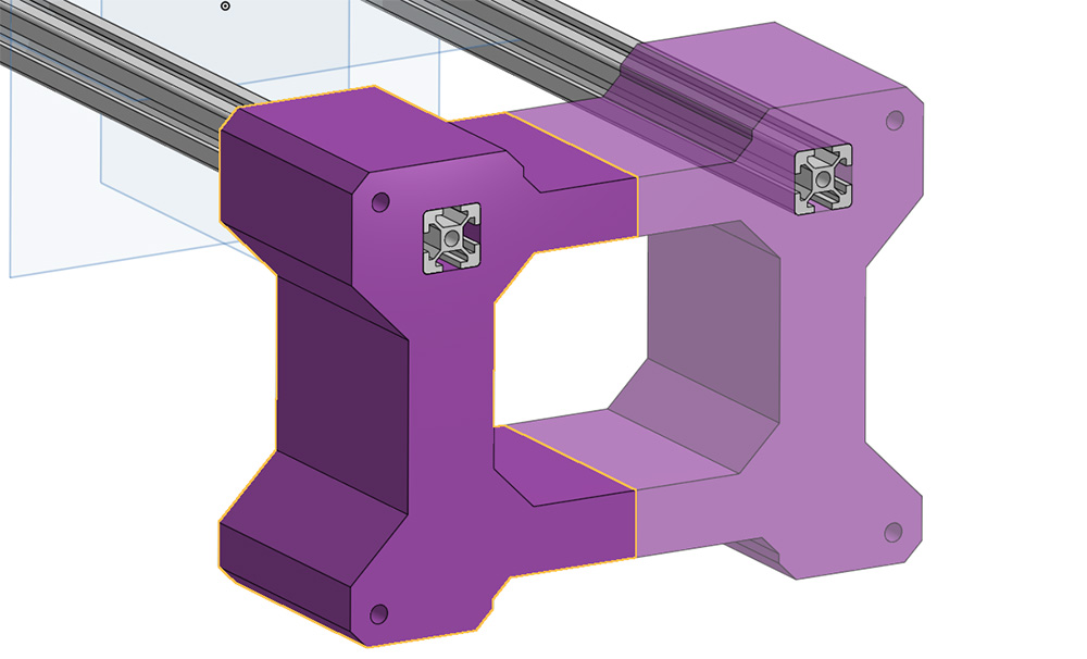
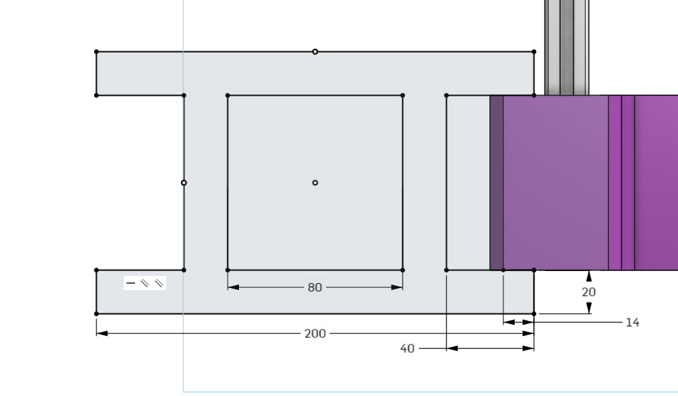
The order that we have modelled this in allows us to change a dimension upstream (such as the 2020 length, or distance between the 2 extrusions), and all the features and parts downstream will be automatically adjusted to fit these changes. The round holes in the purple part are where I intend to place some m8 bolts to mount the suspension arms to.
Speaking of suspension arms, lets model some. To start I sketched this top down view of the arm. The thickness of this was defined off the width of the purple part, so if the thickness of the purple part changes, then the width of the arm will change with it. Onshape doesn't show it, but many of the dimensions in this sketch are also variables to allow for things like arm length to be easily changed later.
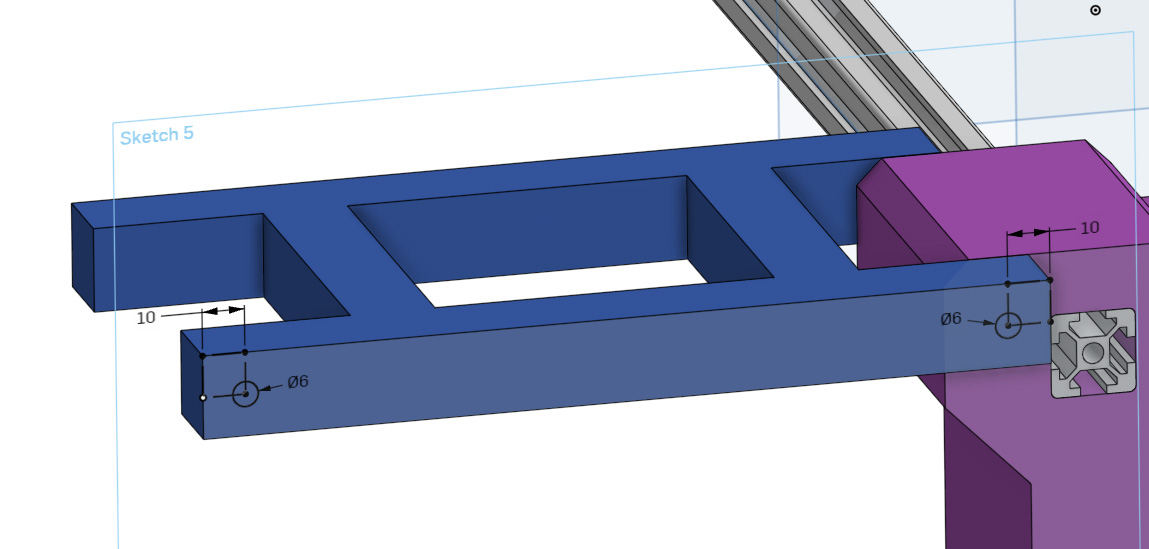
I then extruded that piece down and then sketched and extruded these holes on the side. These use variables to ensure that they will align with the holes we extruded on the purple part, and we will be using m6 bolts to act as a hinging joint to connect the arm to the purple chassis part.
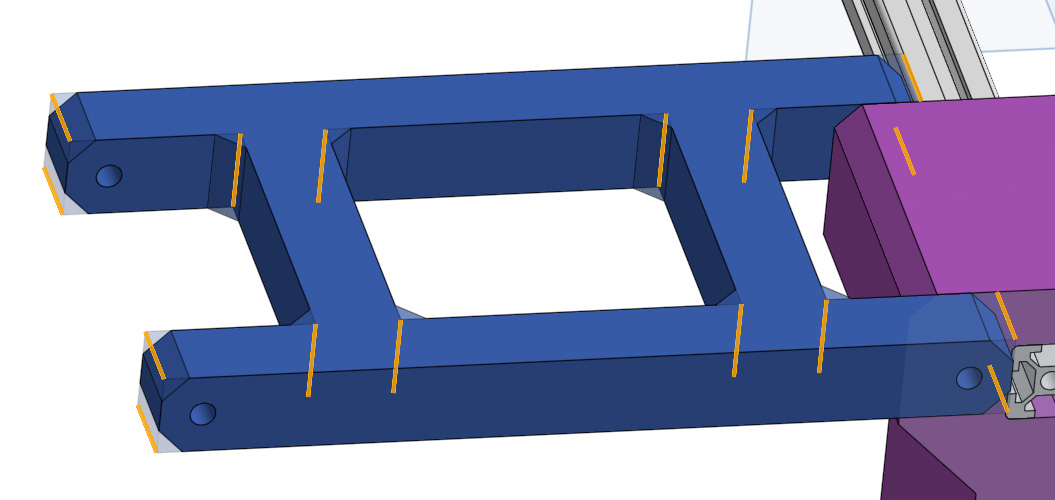
Then the edges were chamfered off, mostly for visual aesthetics this time. The 45 degree overhang that chamfers create are more 3D-printable than a rounded edge. Ussually my parts are modelled with print orientation in mind and it is modelled around that, but it can't hurt to chamfer ever edge just in case. And it looks way cooler... And with that the arm is finished.
I then repeated the same process to produce a second arm centred on the lower m6 hole on the purple part. It would of been smarter to just copy the whole part and move it down the variable-ified distance between the hole, but I modelled it as a second part as I am using this model as a basis to get my parts printed off, and I had a suspicion that these parts might not be identical in a later version so I created it seperately which allowed me to edit it.

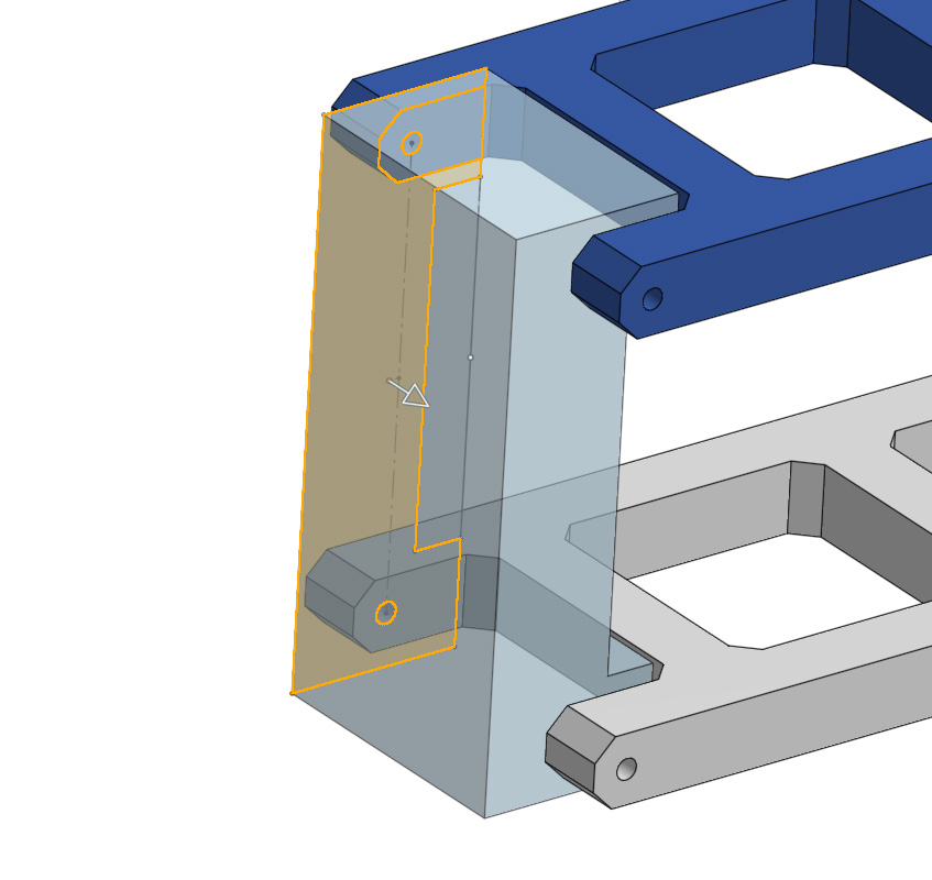
Now we will model the wheel hub mount. To start I made a sketch on the inner side of the arm, then used the holes in the arms to model holes that will be used to mount this wheel hub mount to the arms. So now if the distance between the holes on the purple part is change, the distance between the arms are changed, and then the distance between these holes on the wheel mount are also changed to fit this.
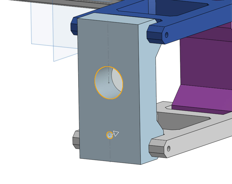
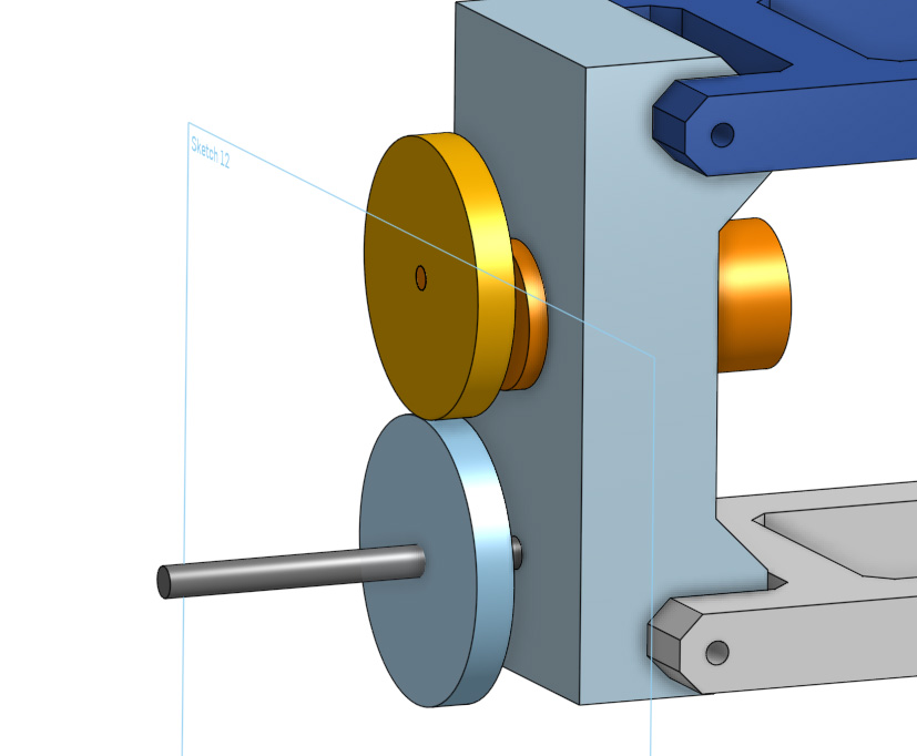
On the surface I sketched and subtracted 2 holes. The large hole is to slot a motor through which will be used to drive the mecanum wheel, and the smaller hole (which doesn't reach the other side, its a tad too shallow), will be used to mount an axle for the mecanum wheel.
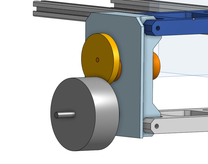
This is where the model starts to become a little place-holdery. Here I modelled up a dummy motor from something I had lying around, and an axle for the wheel to sit upon. I will investigate the actual motor to be used later and will update the model when I get to that, but for this axle, wheel, motor and gears, its moreso just about creating a visual representation to help plan ahead.

More dummy parts, I modelled the 2 gears that will be used to connect the shaft of the motor to the mecanum wheel. These will be updated with the apropraite ratio, or maybe even a belt drive system.
And then a dummy for the mecanum wheel, I am most likely purchasing them and will not go to the effort of modelling them.
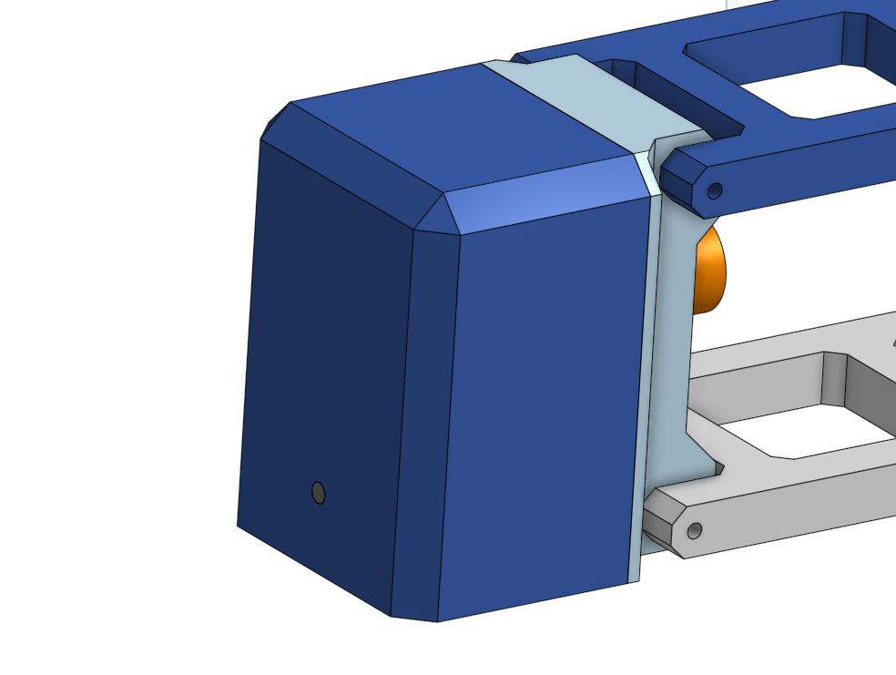
Then I flared out the wheel mount (the light blue part) a little, gave it a bit more width and chamfered it to strengthen it.
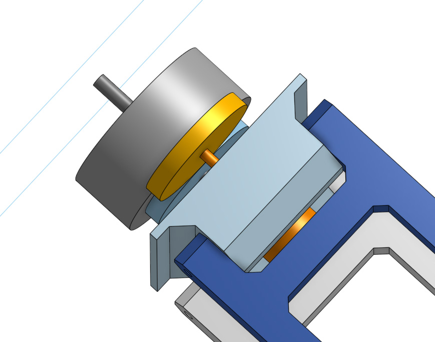
An outer housing to cover the wheel mount was then modelled in 2 sketches and 2 extrudes. The dimensions of this match the wheel mount.
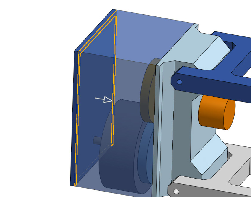
And a chamfer to finish off modelling out parts.
We now have some nice and parametrically modelled parts that are all built upon each other, and defined extensively with variables. If the distance between from the centre plane to the 2020 extrusion sketch were changed, this would change the purple part, the distnace between the arms, the size of the motor hub mount, and finally the dark blue outter housing of it all. This modelling allowed me to tweak the sizes of different parts to achieve an apropriately proportions of the robot I like.
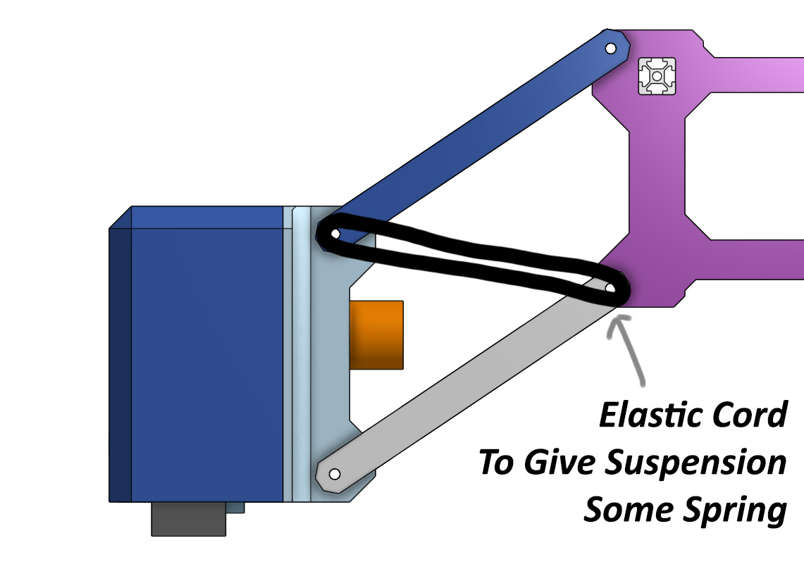
There are some pieces that haven't been modelled, such as the elastic cord or spring that will be strung across the arm mounts to give spring to the suspension. And the top of the robot hasn't been modelled. The focus is the chassis first and once that is done I will move on to the top. The 2020 extrusion was chosen as it will give adequate opportunities to mount.
Now that I have all the parts, I will import them into the assembly stduio and duplicate them to have 4 arms on the robot.
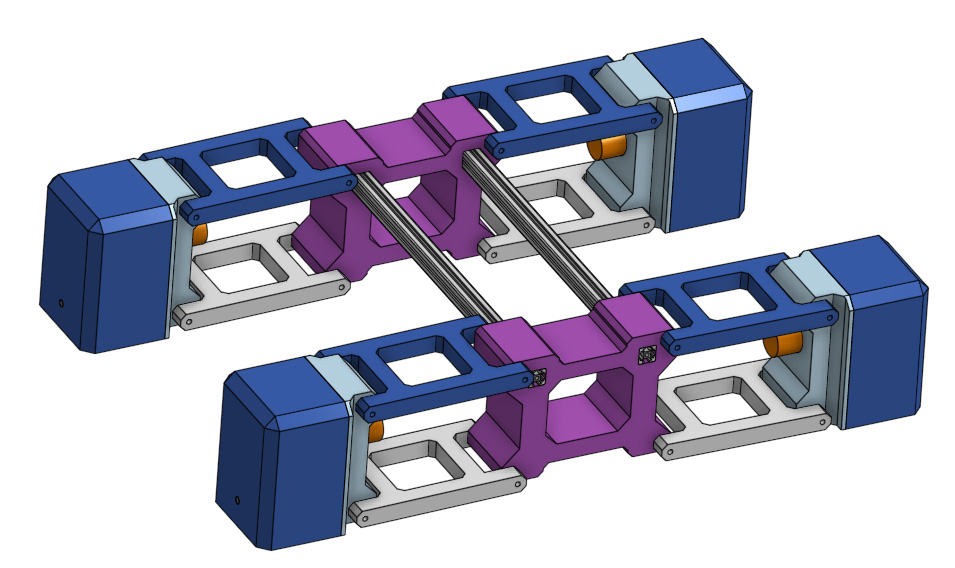
I then used fastener joints to join things together that will be done with fasteners (like the motor hub mount to the outer housing). Then using revolute joints, I mounted the arms to the purple chassis parts and the motor hub mount to allow them to rotate. Then using planar joints, I placed all the wheels in the same plane. These joints allow for a simple manipulatable model of the suspension.
2D Modelling
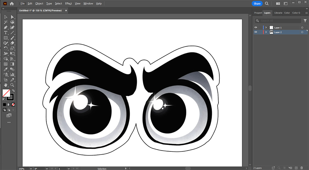
For this section we will be desiging some stickers to cut next week, I'm thinking we make some eyes that we can slap on the robot to give it some personality. For this we will be using Adobe Illustrator and we could use photoshop to make the stickers, but I prefer to use Photopea which is a free and fantastic browser-based version of photoshop. If you have used photoshop there is basically no learning curve to this, it shares a very similar UI and workflow.
Now both of these softwares create images through 2 diffcent methods, vectors and rasters. Illustrator uses vector rendering which is when an image is composed of lines and curves that are mathematically defined with no pixels being used to define the image - kind of like how in CAD features are defined with maths. Photoshop uses raster rending which is when an image is composed of pixels, exactly like your screen. If you keep zooming in, you will eventually see the pixels that compose it as raster images are made up of discrete building blocks. If you scrolled in a vector image though you would never reach a pixels.
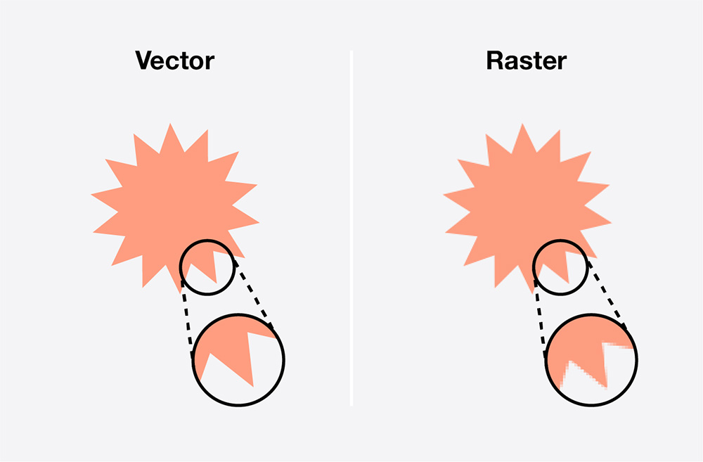
Image Source:The Noun Project
To start with, we will be creating an image of the sticker with photopes. The reason we are using a raster software here is because images on the net are raster-based and it is often easier to edit and manipulate images in a raster form. The original image of the eyes was generated using ChatGPT 4's image generation capabilities, here is the prompt that generated it and the result:
generate me a pair of eyes. just the eyes no face no nothing around it. I just want eyes to make stickers of, almost like googly eyes but make them friendly, make them a little bit cheeky and smug

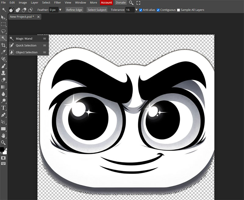
I then copied this image into a new project in Photopea (File -> New), ensuring that the background is set to transparent. To start I removed the grey background with the magic wand tool. Select the grey background to select it, then hit delete to remove it.
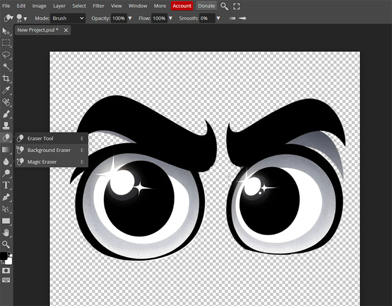
Im not happy with it yet so I used the erase tool to manually remove the smile and some artifacts that were generated. I didn't worry about erasing perfectly around the features and left a little space as we will give it a white barrier around it after.
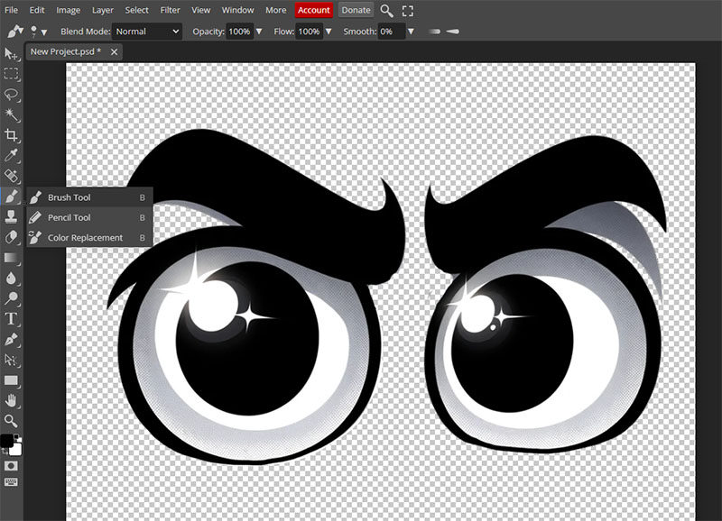
Then I went through and used the brush tool to fix the bottom of the eyes where It generated thing lines. When you have the brish tool, holding alt will allow you to pick a colour to use. I ensured it was the same black as the image.
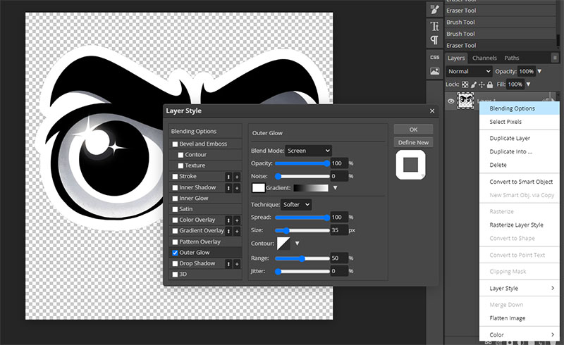
I then added an outer glow which can be found under blending options by right clicking the layer. I set it to white with 100% opacity and spread. Adjust the size to the right thickness you like.
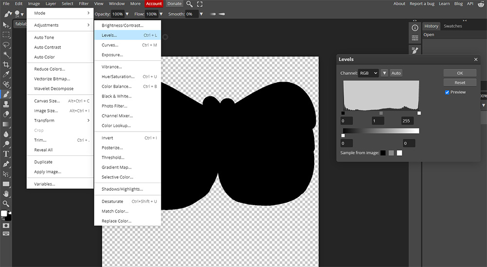
This is now the sticker that we will be printing, this constitutes the actual image of it. Export it as a PNG (so we keep the transparent background), and we are done on this side. We will now use illustrator to make a vector for the vinyl cutter to cut with. There is a really easy way of doing this by first using photopea again. We will start by opening the PNG we just saved, it needs to be the png and not the photoshop file we made. Then hit Image -> Adjustments -> Levels. From this window drag the bottom levels slider on the right all the way to the left. This should give you a completely black silhouette of your PNG. Export this as a PNG as well.
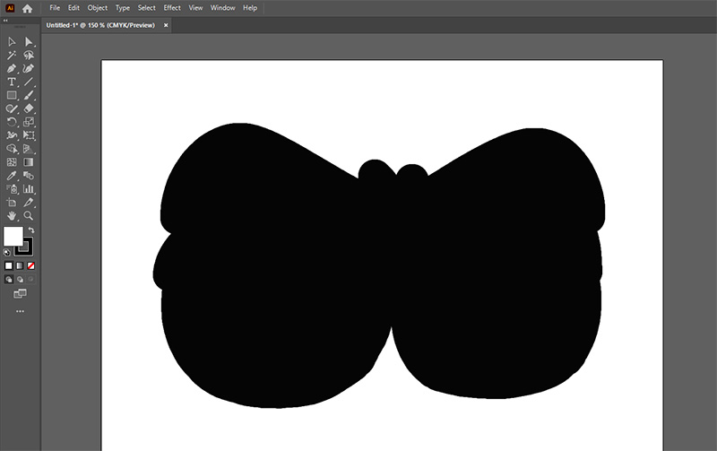
Then we will open Illustrator and create a new A4 image (that is the size of the vinyl we will be cutting on). Then drag in the black png we made and resize it apropriately.
Then use the image trace tool in the bottom right (or select it with Window -> Image Trace), and use the settings in the image below, ensure you tick preview to see your nice new vectors that have been generated from this.
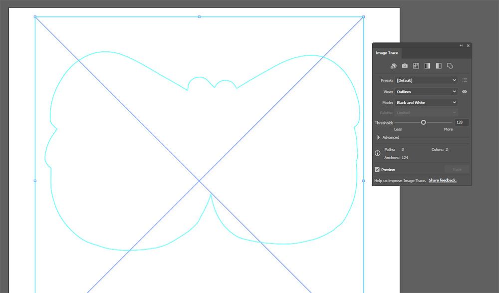
Now we want to get rid of that outer box vector, select the image then in the bottom right under quick actions hit ungroup. Now you should be able to just select the outer box vector and hit delete to remove it. We now have a vector that can be used to make the cut with. Create another layer in the layers tab in the top right and drag the full colour image. Size and align it to the vector we just made and we now have a file ready for the vinyl cutter. This design is a part of the final project as the raster image will be used to print the sticker, and the vector will be used to cut it out.
Final Reflection
Most of my workflows that I have developed over the years have revolved around 3d design, even 2 design that I do is in a 3d CAD software like onshape. While I think there is a place for 2d design in illustrator or ink scape, most of the parts I wish to make will take on design that can be done with sketches in onshape, and will also need to be parametric, it just feels weird doing parametric work in a vector editor. And onshape will be the CAD software of choice for me largely because of its portability, I can work on the same design at work, at home and in the lab, seamlessly in a browser. While it doesn't have some of the more advanced features that fusion 360 or onshape has, it is still good enough for 95% of the projects I will probably ever do. If I had to deal with lots of organic geometries, I might opt to use fusion 360 or even blender.
Files
Media Compression
To keep media files small for this site, I will primarily be using 2 tools to compress my files.
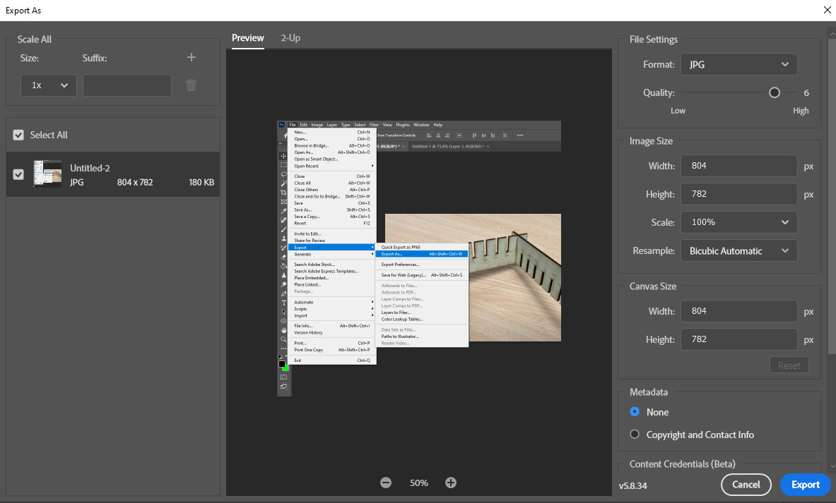
For photos, I will just be using the export settings in photoshop. If you File > Export > Export As..., you are greated with a variety of settings that can be used to compress your image size. Exporting in the JPEG format, lowering the resolution as much as reasonably possible (I am for images about 900 pixels in width or height), and lowering the JPEG quality (5 or 6 works well), will be enough to get most images under 100kb.
For videos and gifs (pronounced gif), I will be using Handbrake, an incredible open source transcoding tool. Video compression is a little harder to manage as its very easy to get a deepfried low-quality videos with audio that sounds like it is coming through a string on a can.
For my best settings in Handbrake, I start by setting it to the fast 720p 30 preset, as we dont really need higher than 720p for a video showing a laser cutter in motion. I will then use the h.265 video encoder as it is very size efficient, and I will set an average bitrate of about 1000-3000 kbps. The rest of the settings are left to defaults.
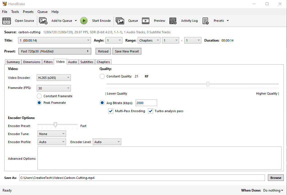
Then after exporting, I will check the file size and quality. If its too low quality, bump up the bitrate, if you need a smaller file, bump it down.