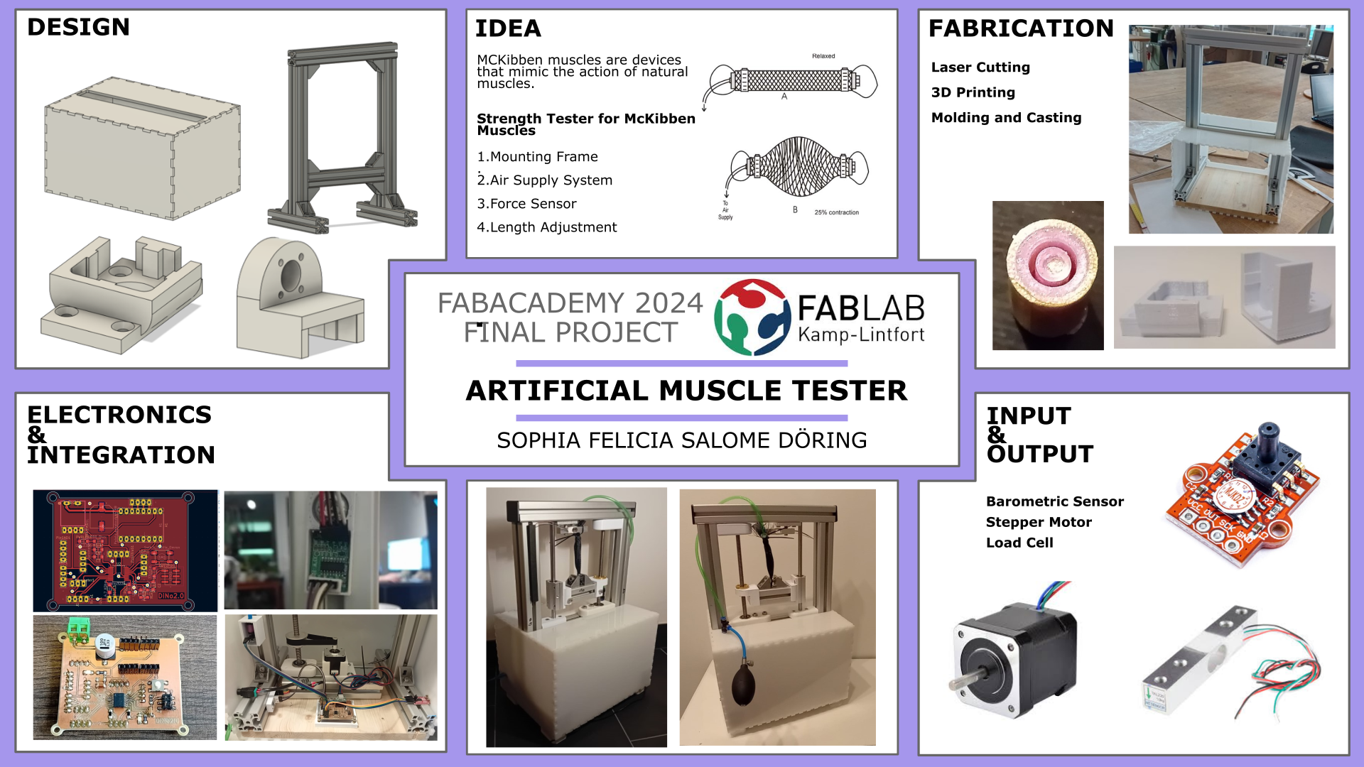
Final Project
Hero Shots
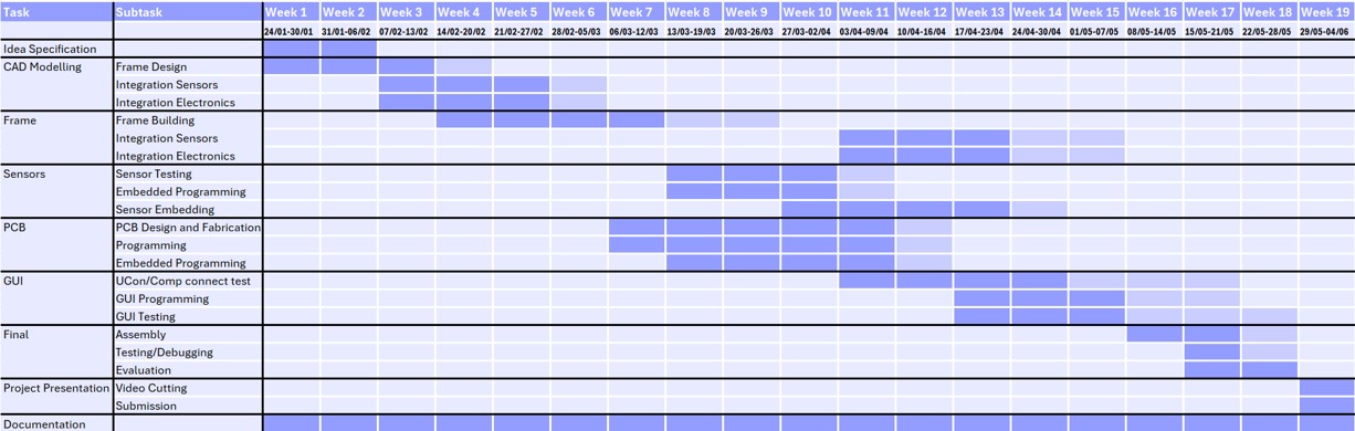
Project Planning and Management
Research
For a material tester for artificial muscles, ther first question that occurs is: What do I want to test? In general there are different types of artificial muscles, with several orders of magnitude both size and generated force, e.g. Mingtong et al. 2022 researched miniature artifical muscles with reinforced nylonfibres (length of a few centimeters) for medical devices, while other researchers such as Wickramatunge and Leephakpreeda 2010 focus on pneumatic artificial muscle (PAM) with sizes of a few centimeters to more than a meter.
The other question is: What do I test for? According to a video from the ARC Centre of Excellence for Electromaterials Science (ACES) there are four different testing parameters: Isotonic actuation, isometric actuation, actuation against a spring in series, and hysteresis in loading and unloading.
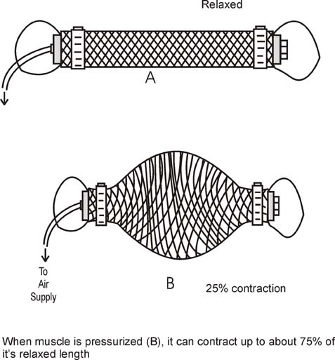
It is important to decide on the type and test first. At the Hochschule Rhein-Waal, where I am working and studying, there are two types of artificial muscles produced McKibben (pneumatic) and nylon-based artificial muscles.
I decided to go for the McKibben muscle testing at first, and (if possible) make the tester adjustable for different types of artificial muscles.
Components
- Testing Apparatus (Frame): A testing setup that allows controlled application of forces (pressure) to the artificial muscle. It hold the muscle in place during the measurements.
-
Sensors:
- Force sensors or load cells to measure the force generated by the artificial muscle.
- Devices that moves the mounting points of the artificial muscle up and down to test different lengths of muscles.
- Pressure sensor for the McKibben muscle
- Data Processing: Instruments or systems to collect and record data from sensors.
- Calibration Standards: Calibration to ensure the accuracy of the measurement devices.
- Artificial Muscle Mounting: The frame should provide a secure and adjustable mechanism for mounting and securing the artificial muscle during testing.
- Compatibility with Muscle Sizes: The frame should be designed to accommodate various sizes of McKibben muscles to ensure versatility in testing.
- Stability and Rigidity: The frame should be stable and rigid to minimize any unwanted vibrations or oscillations during testing, ensuring accurate measurements. Additionally, the load should be one axial.
- Weight Capacity: The frame should be designed to support the weight and forces generated by the artificial muscle without compromising its structural integrity.
- Cost-Effectiveness: The materials and manufacturing processes used in the frame construction should be cost-effective while meeting the required performance criteria.
- Compatibility with Sensors: The frame design should consider the integration of sensors for force measurement, ensuring compatibility and accurate data acquisition.
- Precision Measurement: Sensors should provide precise measurements of force.
- Range of Measurement: Sensors should cover a wide range of force measurements..
- Response Time: Sensors should have a fast response time to capture rapid changes in force or displacement during dynamic testing.
- Being mounted to the frame
- keeping the shaft in place with no rotation (1 part)
- having a linear bearing pressed in to keep the threaded shaft constraint (3 parts)
- Milling of three holes to keep the shaft in place and get the threaded shaft through the profile of the frame.
- Cutting the shafts to the right size
- Mount a piece of profile to the bottom to align the stepper motor and the threaded shaft
- Change the height of the mounting system to adjust it to the length of the muscle
- Get the first measurements of the mounted artificial muscle to make sure it is in a relaxed position (no pressure and no force)
- To start and stop the measurement
- to get a graph of the measurement afterwards
- ✓ CAD design(2D & 3D)
- ✓ Subtractive manufacturing
- ✓ Additive manufacturing
- ✓ Electronics design & production
- ✓ Programming
- ✓ Interface development
- ✓ System Integration
- ✓ The frame should provide a secure and adjustable mechanism for mounting and securing the artificial muscle during testing.
- ✓ The frame should be designed to accommodate various sizes of McKibben muscles to ensure versatility in testing.
- ✓ The frame should be stable and rigid to minimize any unwanted vibrations or oscillations during testing, ensuring accurate measurements. Additionally, the load should be one axial.
- ✓ The frame should be designed to support the weight and forces generated by the artificial muscle without compromising its structural integrity.
- ✓ The materials and manufacturing processes used in the frame construction should be cost-effective while meeting the required performance criteria.
- ✓ The frame design should consider the integration of sensors for force measurement, ensuring compatibility and accurate data acquisition.
- ✓ Sensors should provide precise measurements of force.
- ✓ Sensors should cover a wide range of force measurements.
- ✓ Sensors should have a fast response time to capture rapid changes in force or displacement during dynamic testing.
Requirements
Testing Setup/Frame
Sensors
Design
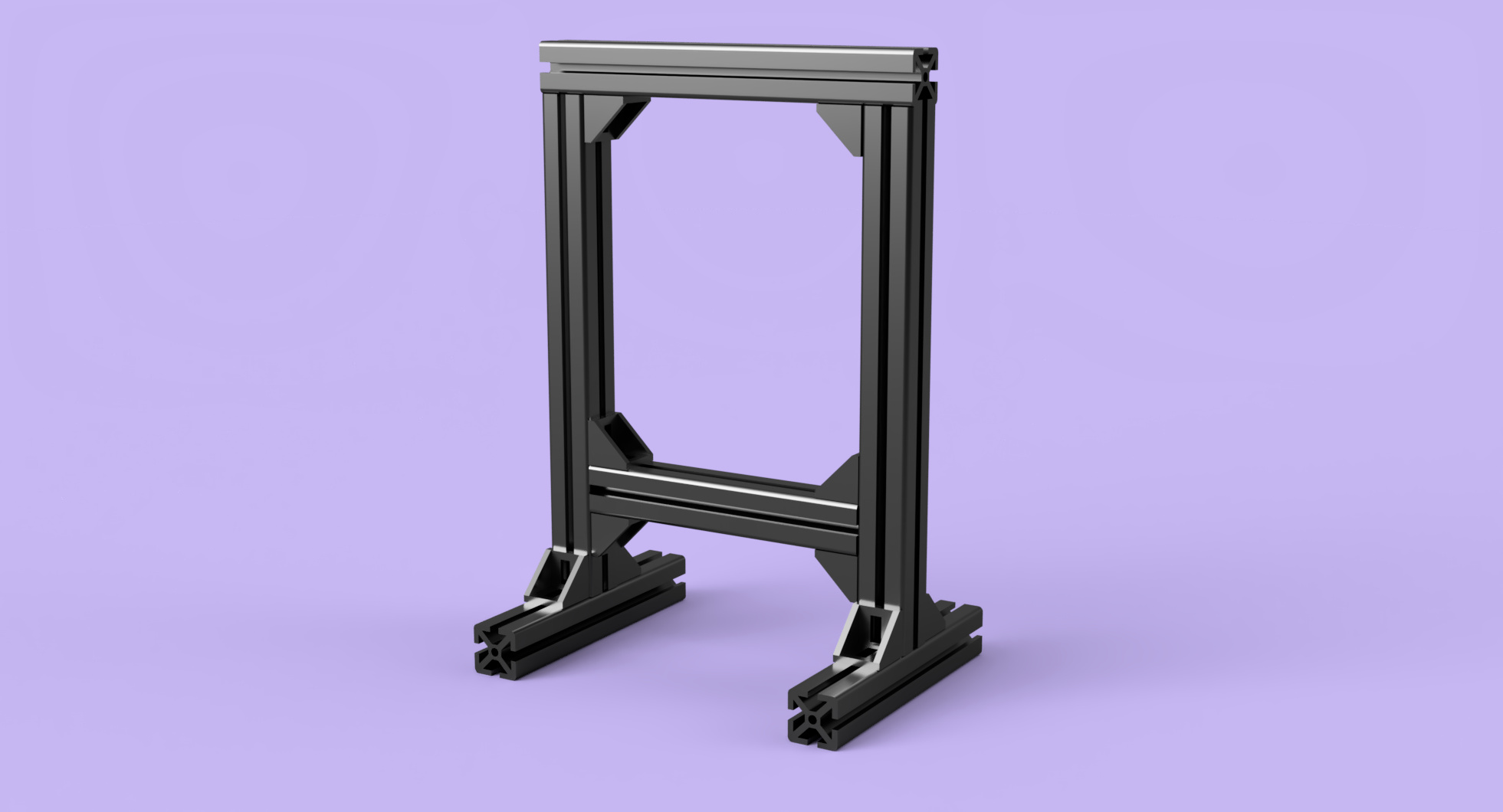
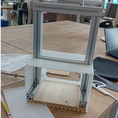
Frame
The first design of the final project was created in week 02 of the Fabacademy journey. In this instance the frame outline was design and animated.
Over time a lot of changes have happened to the design.
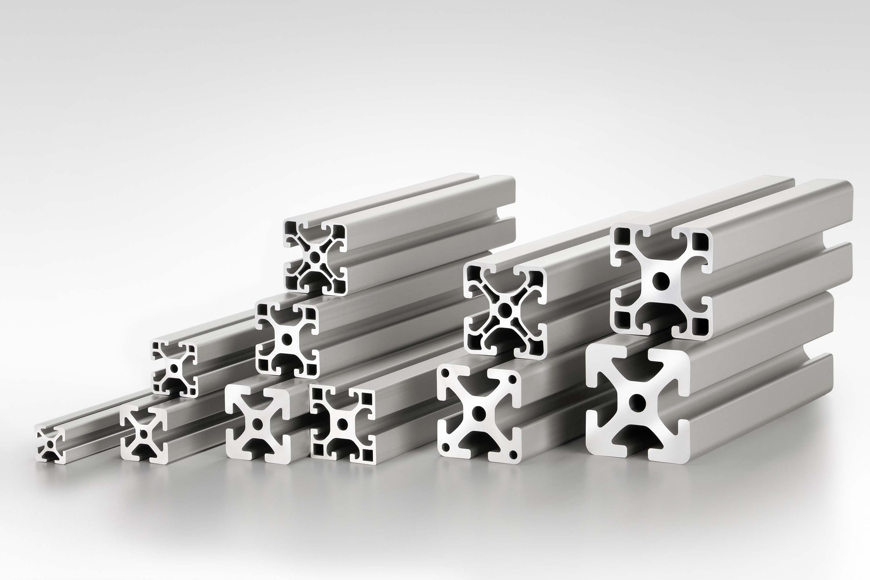
The frame for stability when testing the articial muscles should provide a enough tensile strength while testing. A common component used for these kind of machines are Aluminium profiles. Instead of the P5 20x20 mm profiles, I decided to use the P8 40x40mm as it can withhold 2500 N of Permissible groove extraction force which gives a safety factor of 5, in my opinion needed for this design.
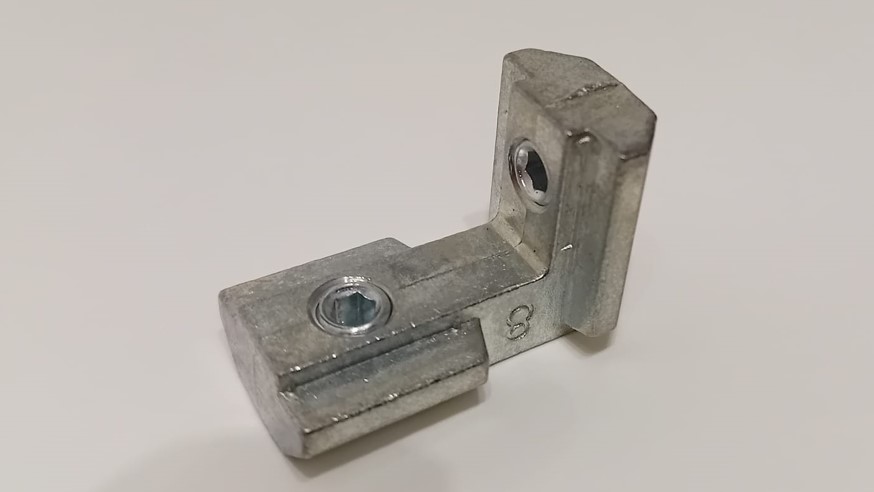
Additionally, I used the angle brackets to connect the profiles to buil tthe frame, with inserted t-Nuts with balls and M8 Sockets Head screws.
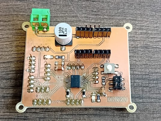
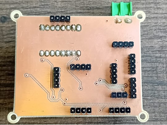
PCB
The design of the PCB was created in week 08 of the Fabacademy journey.
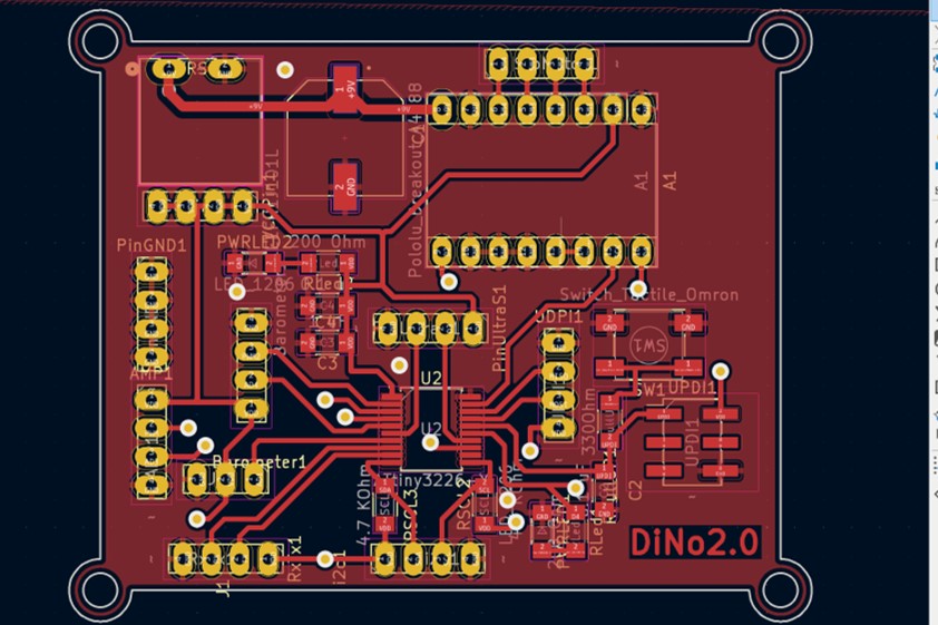
finished design of the front layer
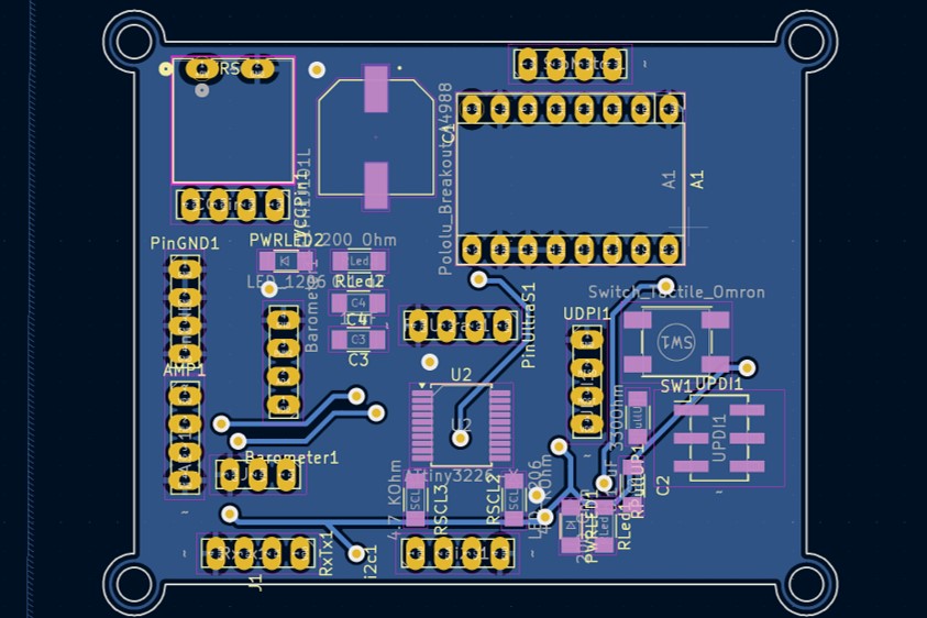
finished design of the back layer
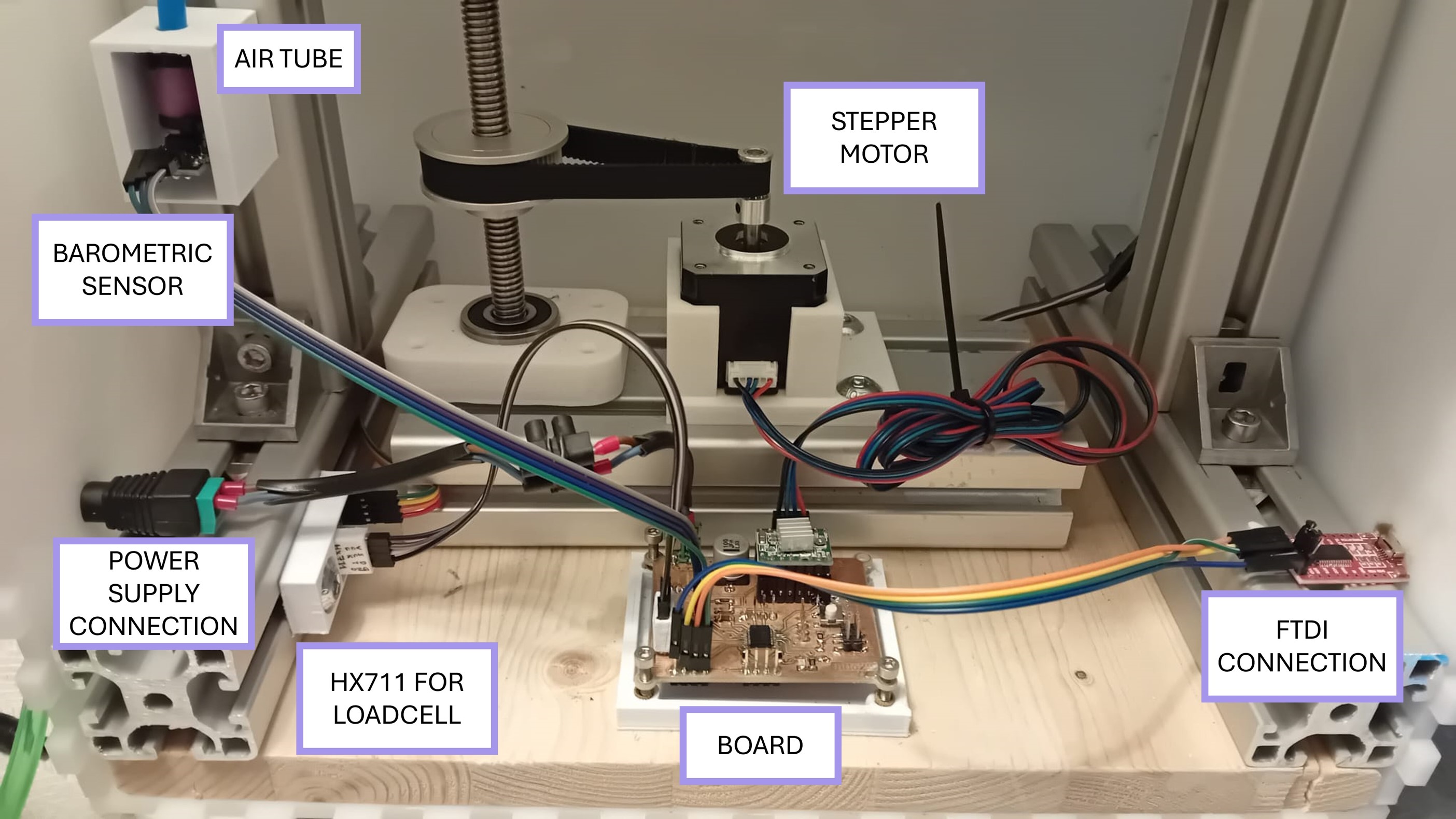
System Integration
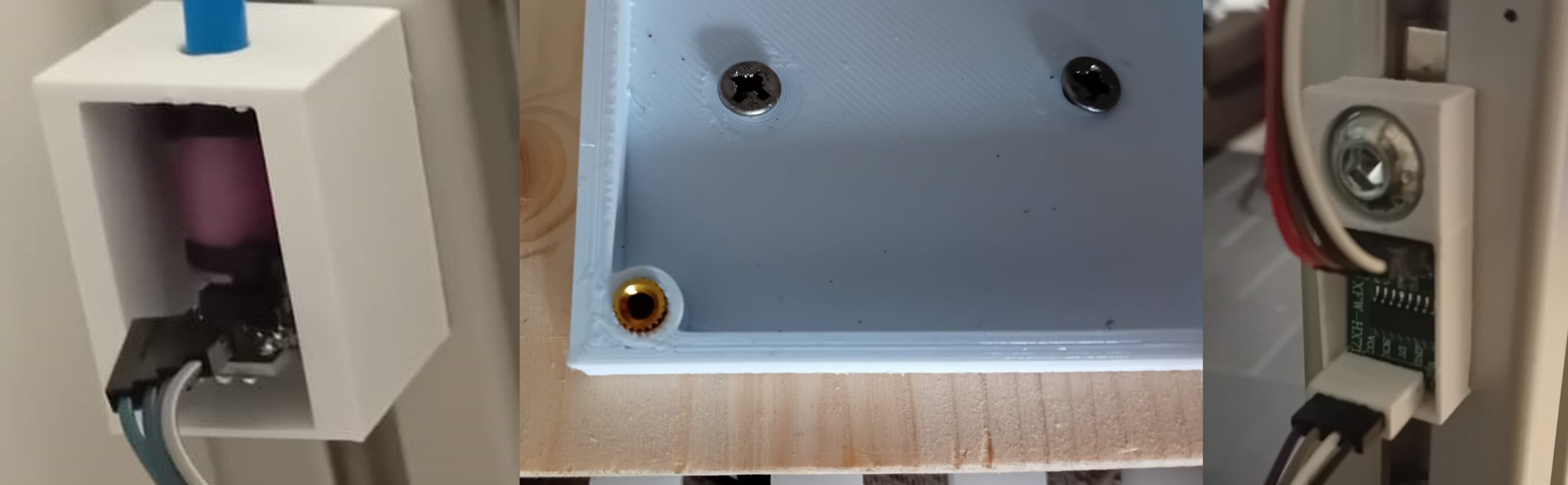
Connecting the Barometric Sensor
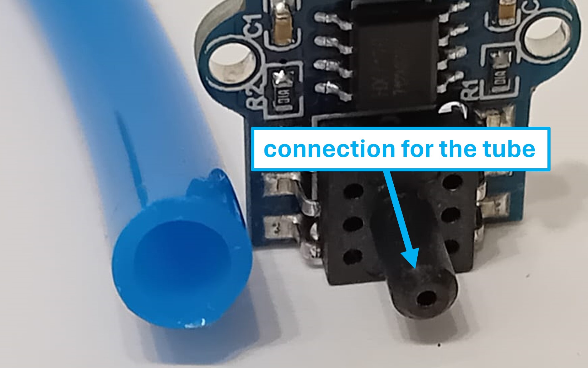
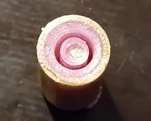
When the barometric sensor arrived, I noticed that the tube meant to connect to the sensor had a larger diameter than the sensor's connection. Therefore, I designed a mold for a silicone connector to bridge this size difference.
In this design, I addressed the diameter difference by adding a layer of silicone. To secure this layer, I decided to use a zip tie.
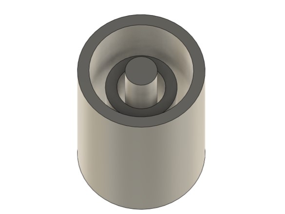
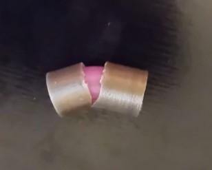
In my initial design, I planned to simply fill the mold with silicone. However, Roland Grichnik pointed out that the viscosity of the silicone could be a challenge, as it might not flow into the small gaps of the mold. Therefore, I created a second design to address this issue.
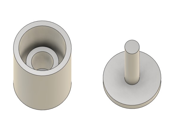
The second design includes the idea of filling the first part of the mold (left) with silicone and then placing the second part (right) onto the first. This process effectively displaces some of the silicone in the first part, ensuring it fills all the small gaps and details.
Electronics Box
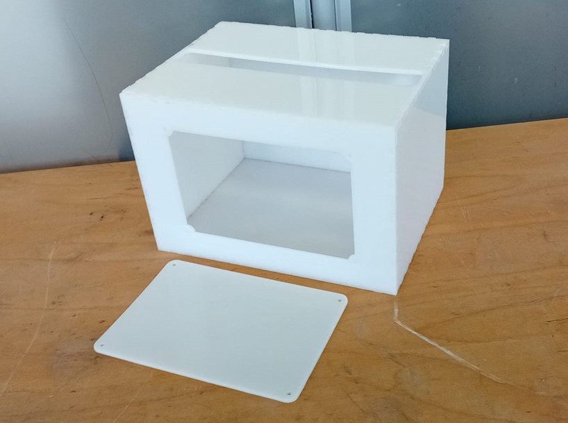
To cover the electronics and part of the linear motion system, I design a box for the bottom part of the AM-tester.
I designed a box to laser cut out of a sheet of POM ( Thickness 5.5 mm). Which was not bought, but leftovers were used from the lab in Kleve.
I created a parametric design of the box.
I exported needed faces for laser cutting as .svg files and imported them to Inkscape. Additionally, I design a door in Inkscape, so there electronics are reachable and a hole for the power supply.

Enclosure for Components
For system integration I created different components, which are described in detail in week 17.

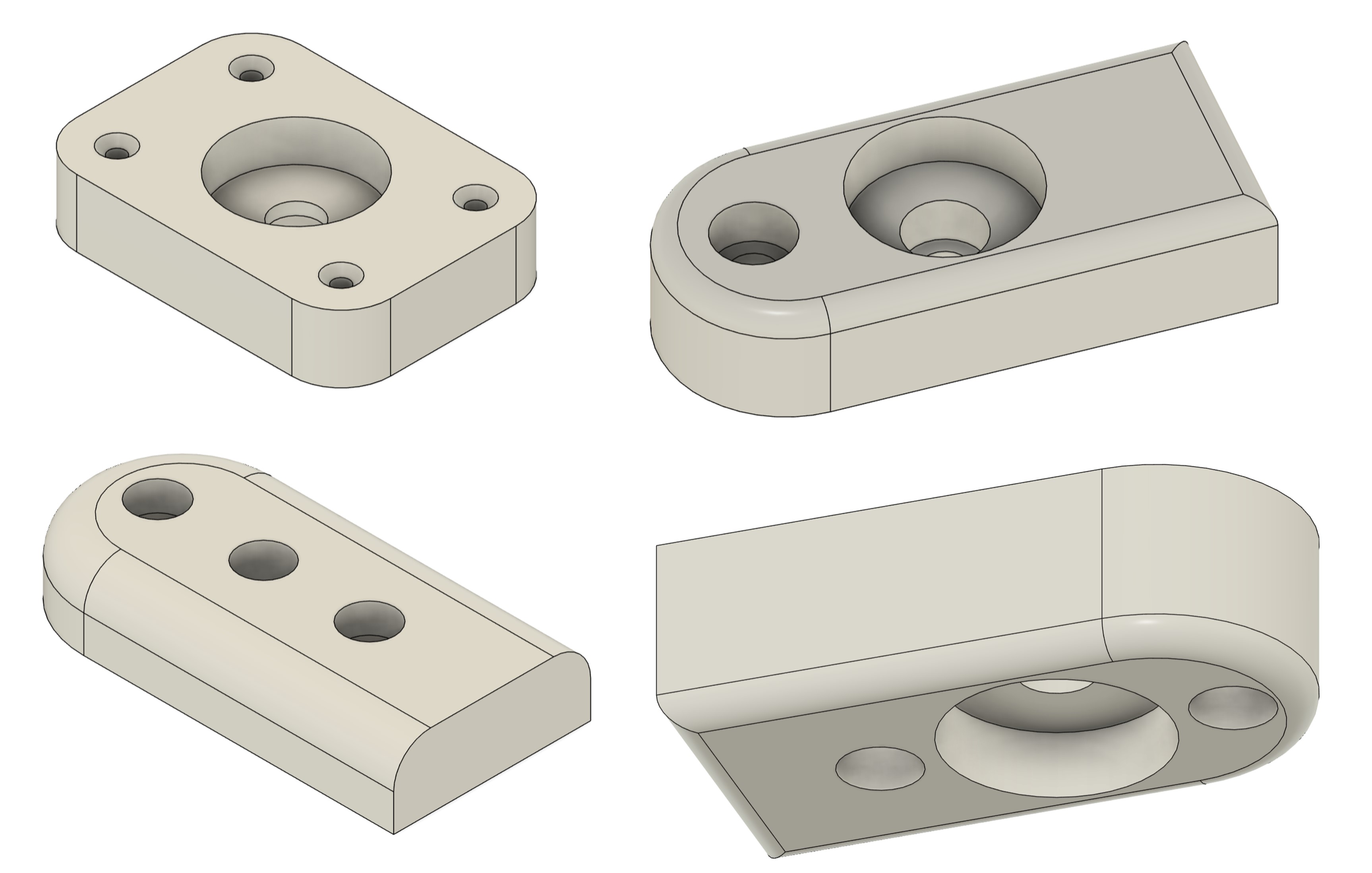
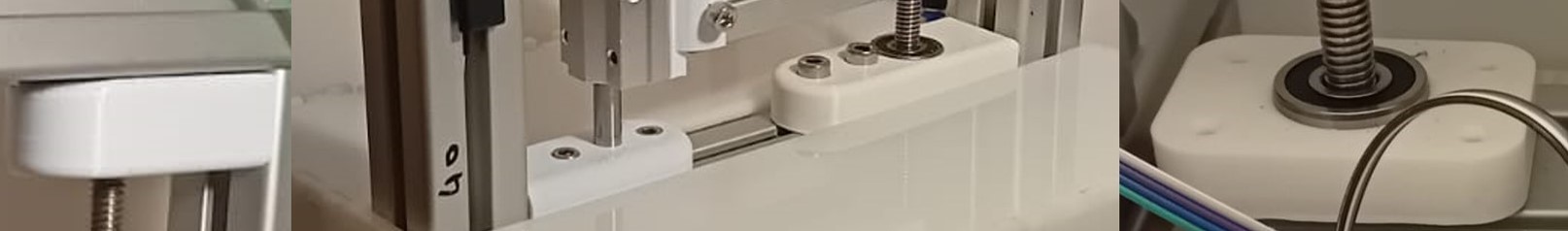
Linear Motion System
The linear motion system is depending on three components:
The first design of the pieces is shown in the picture below:
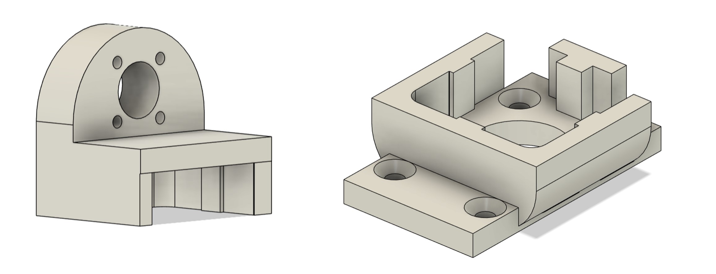
After printing the first version, I noticed that the tolerance of the parts is too big. Therefore I created a version that included set screws. The second version is shown in the picture below:
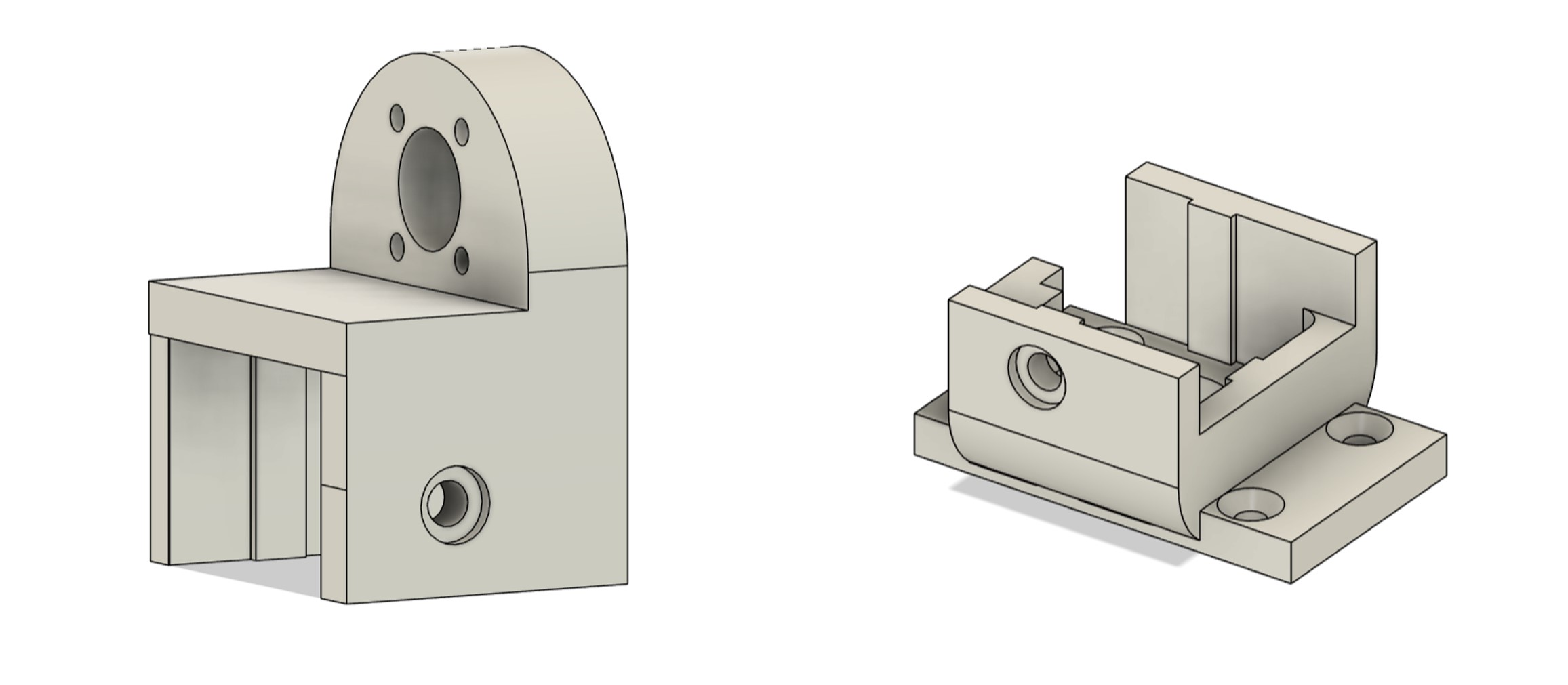
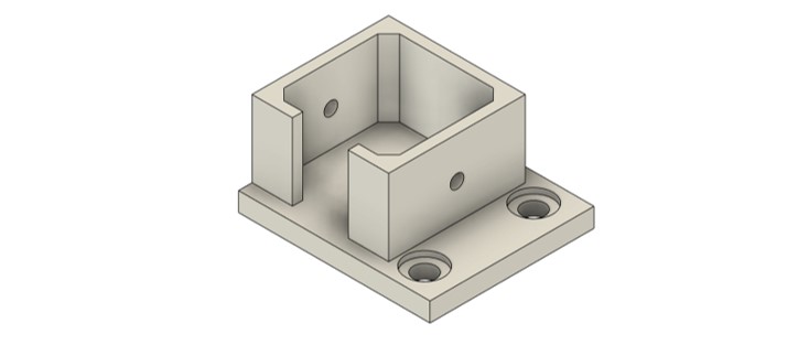
Additionally, I needed some mounting pieces for the the linear drive system as the shaft needed to be fixed to the frame with no moving tolerance and the threaded shaft needed three bearing so it rotates but is contraint for any linear movement. Therefore, four parts needed to be created, which were limeted by:
The design of the parts can be seen below:
To make sure that the stepper motor stays in position for the linear motion system, I design a mounting box for the motor that can be screwed to the aluminum profile:
Bill of Material
Fabrication Materials
| Amount | Material | Description | Link |
|---|---|---|---|
| 1 | PETG Filament | PETG White, 1,75 mm / 1000 g | HERE |
| 1 | ECOFLEX™ 0030/1 | - | HERE |
| 1 | Polyacetal Pom Sheet | 1mx2m Polyacetal Pom Sheet | HERE |
| 1 | PLA Filament | ecoPLA White, 1,75 mm / 1000 g | HERE |
Building Material
| Amount | Material | Description | Link |
|---|---|---|---|
| 1 | Trapezoidal threaded spindle | T10x2x2-550mm | HERE |
| 2 | Trapezoidal threaded nut | T10x2x2 | HERE |
| 1 | Linear bearing | SCS10UU Linear bearing für 10mm Shaft | HERE |
| 3 | Deep groove ball bearing | Deep groove ball bearing 6200 2RS 10x30x9 mm | HERE |
| 1 | Alu Profile 8 40x40 | 2000mm; light; 4 sides open | HERE |
| 1 | Shaft rod | Cf53 Steel - 10 mm - length 510 mm | HERE |
| 1 | Timing belt | 1 meter GT2 timing belt open 10mm | HERE |
| 10 | Angle bracket | Angle bracket 40 x 40 groove 8 light with hammerhead screw fastening | HERE |
| 10 | Angle bracket | Angle bracket 40 x 40 groove 8 light with hammerhead screw fastening | HERE | 10 | T-Nuts with ball | M6/ M8 T-Slot Nuts 40 Series T-Slot Nut for aluminum profile extrusion slot | HERE |
Electronics Materials
| Amount | Material | Description | Link |
|---|---|---|---|
| 1 | Barometric Module | TC-10093132, up to 40 kPa pressure | HERE |
| 1 | Stepper Motor | NEMA 17, used in week 06 | HERE |
| 1 | Motor Driver | a4988, used in week 06 | HERE |
| 1 | Load Cell | RB-Phi-120, Tension Micro Load Cell (up to 50 kg) | HERE |
| 1 | Load Cell Amplifier | HX 711 | HERE | 1 | Power Supply | 24V power supply unit 1.5A plug-in power supply unit | HERE |
Fabrication
Frame
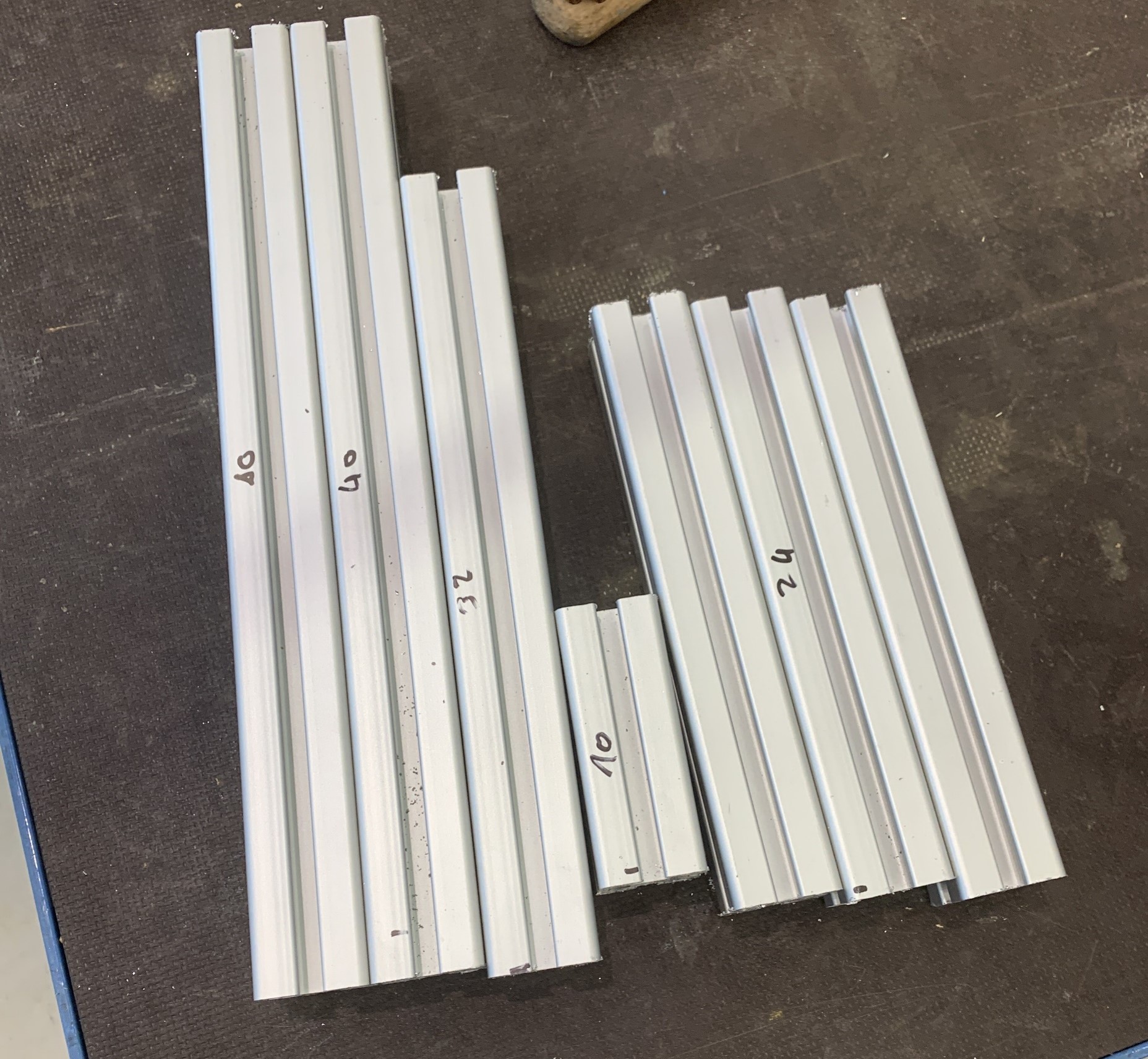
As the aluminium profile was delivered per mail from FabLab Kamp-Lintfort to FabLab Kleve, my instructor decided to cut the profile in the right length of each piece, so the delivery is easier. My work started with assembling the frame.
Unfortunately, the delivering of the parts took 3 weeks. Therefore, I was pretty stressed out (and still am), as the time was running out.
My instructor additionally ordered angle brackets, I have never used before for the aluminium profiles. As these brackets are not as visible and big as the other ones I decided to used these for the connecting points visible in the end product (not covered by the electronics box).
As the profiles arrived I started to built the frame.
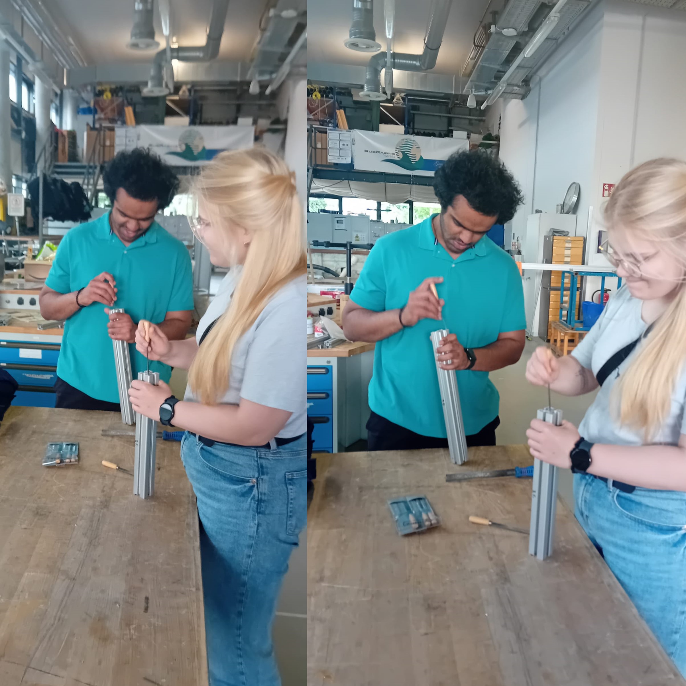
My friend Manav and I started filing the profiles because the cutting edges were relatively sharp and uncomfortable to handle.
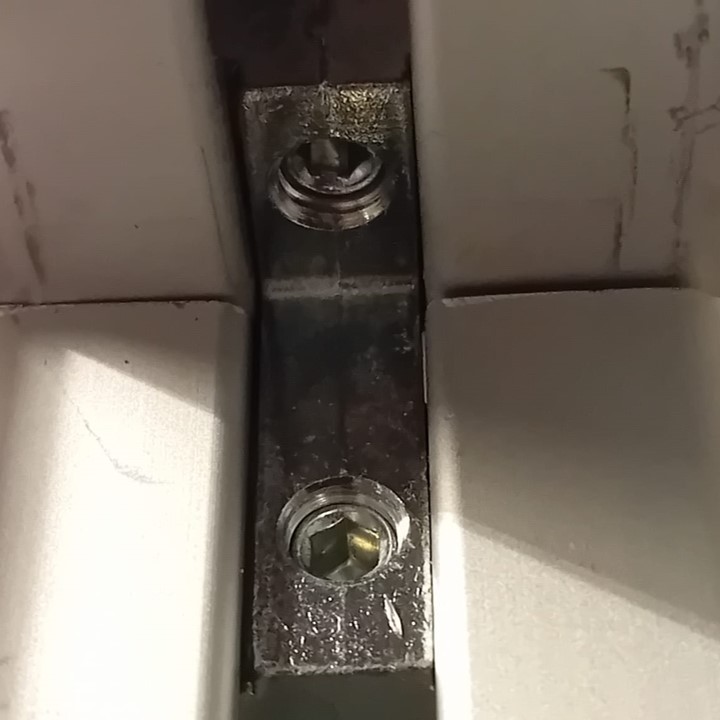
I used angle brackets to connect the profile parts and tightened them with an Allen key.
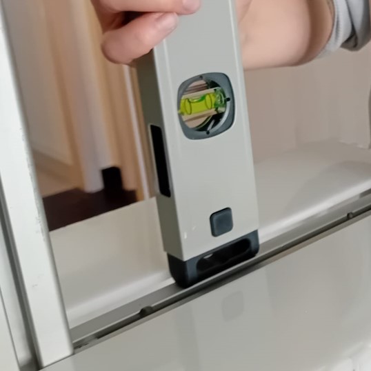
I checked the assembly and connections with a spirit level to ensure everything was straights.
Additionally, I checked if everything fit into the electronics box, which I had fabricated before the frame since I already had the materials and fabrication tools on hand.
PCB
The production of the PCB was done in week 08 of the Fabacademy journey.
System Integration
Connecting Barometric Sensor
As I decided to create the connector out of silicone, I casted my mold.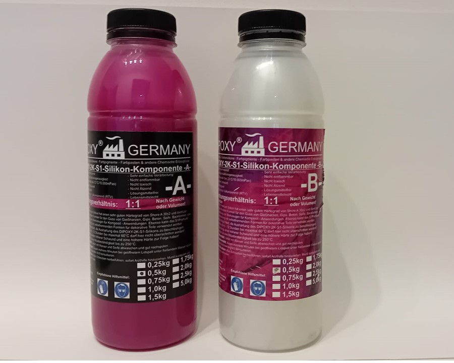
I used Dipoxy Premium 2 Component Silicone Type S1 Dubling Silicone instead of the ecoflex.
As written in the data sheet I mixed the components 1:1 and carefully stirred them until a homogenous fluid was created.
I then filled my mold with the silicone.
I then put the upper part of the mold on the bottom part.
After 12 h the silicone was harden and the mold was able to be removed. I the upper part some bubbles have built.
In the bottom of the mold the silicon seemed to be equally distributedd in the mold.
Unfortunately, I had to break the mold as I could not get out the silicoen of the mold.
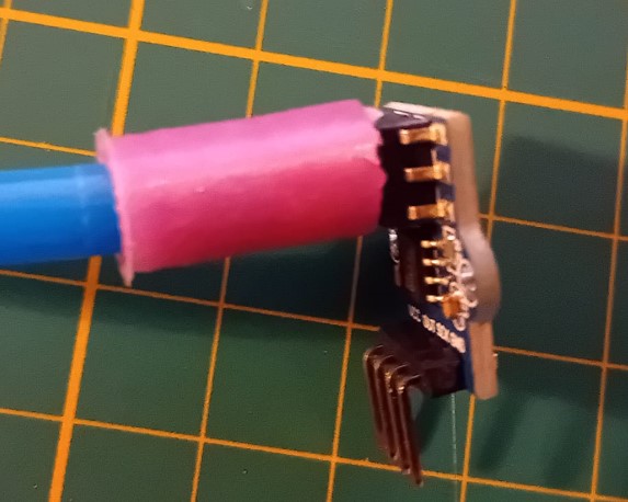
I checked if the part fits and it did. :)
Electronics Box
To cover the electronics and part of the linear motion system, I design a box for the bottom part of the AM-tester. I then laser cut the design and used POM of 5.5 mm. I used the power of 70 and a speed of 10. Because of the thickness of the material it cut two times.
Afterwards, The cut edges look like this:

Therefore, i cleaned the edges with Isopropanol, which worked out very well. Thereafter, I put the pieces together:
Enclosure for components
For system integration I fabricated different components by 3D printing them. The components are described in detail in week 17.
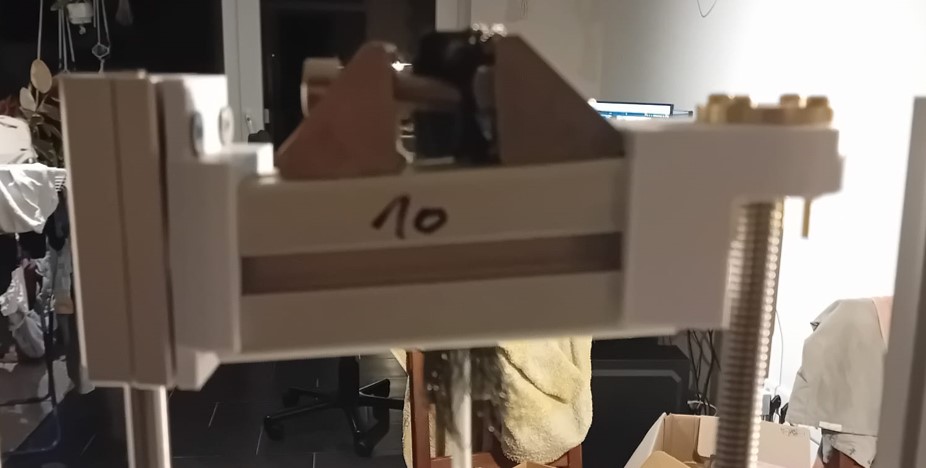
Finished Assembly
Linear Motion System
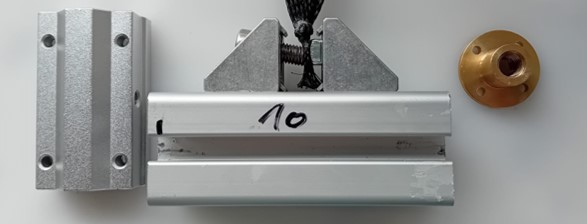
For the linear motion system, several manual steps where done:
I printed the first design of the linear motion parts with an Ender 3 v2 and used the PETG Filament, with a bed temperature of 85°C and a nozzle temperature of 240°C.
Additionally, I printed the designs of the mounting parts. I mounted the shafts with the 3D printed parts to the frame.
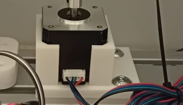
I also 3D printed the stepper motor mounter.
Testing
PCB
The testing for the PCB was done in week 08 of the Fabacademy journey.
Output Devices
The first test with the included output device can be find in week 09 of the Fabacademy journey.
The first test of the stepper motor included the moving of the stepper and connection to the board.
Input Devices
The testing of the load cell was done in week 11.
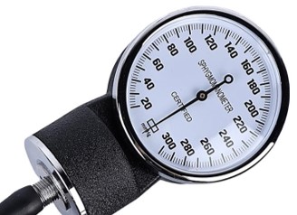
For the barometric sensor I tested the raw output first. To know what pressure I generate and to calibrate the barometric pressure sensor I used an analog pressure sensor for blood pressure measurements.
I used C++ and the Arduino IDE to the raw output.
const int sensorDataPin = 2;
const int sensorClockPin = 3;


void setup() {
	// Initialize serial communication for debugging
	Serial.begin(9600);

	// Set up the pin modes
	pinMode(sensorDataPin, INPUT_PULLUP); // Enable internal pull-up resistor
	pinMode(sensorClockPin, OUTPUT);

	// Initialize the clock pin to LOW
	digitalWrite(sensorClockPin, LOW);
}

void loop() {
	int sensorValue = readSensorData();
	long mappedValue = map(sensorValue, 0, 32767, 0, 65535); // Map the sensor value to a new range

	Serial.println(mappedValue);
	delay(100);
}

int readSensorData() {
	int data = 0;

	// Assuming the sensor sends 16 bits of data
	const int bitLength = 16; // Adjust if your sensor sends a different number of bits

	for (int i = 0; i < bitLength; i++) {
	// Pulse the clock pin
	digitalWrite(sensorClockPin, HIGH);
	delayMicroseconds(20); // Adjust timing as needed
	digitalWrite(sensorClockPin, LOW);
	delayMicroseconds(20); // Adjust timing as needed

	// Read the data pin
	int bit = digitalRead(sensorDataPin);

	// Shift the data and add the new bit
	data <<= 1;
	data |= bit;

	}

	return data;
}
The output is shown here:
Unfortunately, the maximum was already achieved at 10 kPa. I tried to change the mapping, but the sensor seemed to have a maximum measurement range of 0-10 kPa.
Additionally, to make sure that it is not the code but the sensor I tested the output with a multimeter.
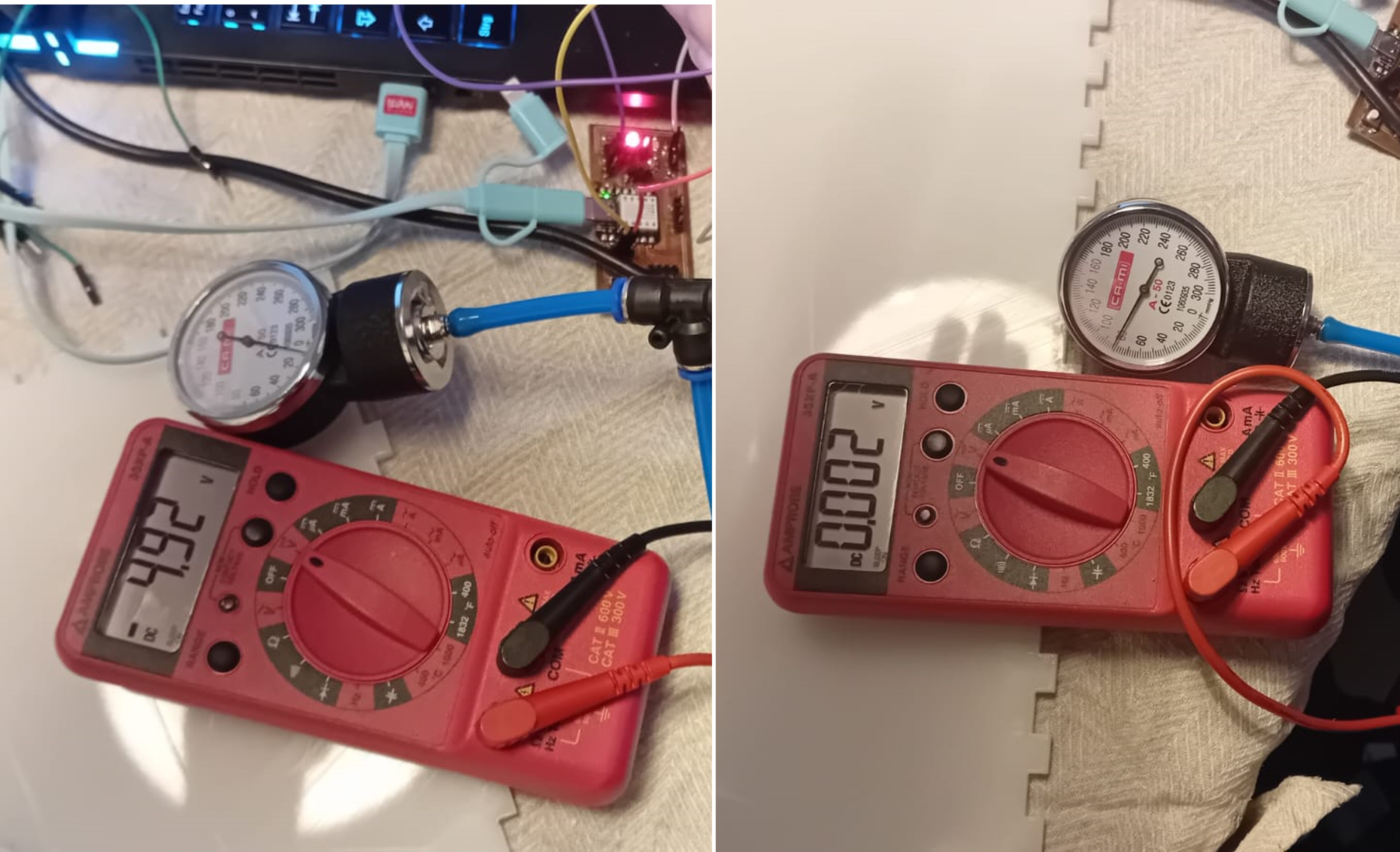
As the measurement on the source showed that the sensor is the problem, my instructor suggested that the sensor could have counterfeit components. Therefore, I ordered a new one from another supplier.
Unfortunately, the new sensor had the same problem and stopped at around 12 kPa. I decided to use the sensor and just make measurement up to 12 kPa.
I then calibrated the barometric sensor with 3 different measurements.
	const int sensorDataPin = 2;
	const int sensorClockPin = 3;


	void setup() {
		// Initialize serial communication for debugging
		Serial.begin(9600);

		// Set up the pin modes
		pinMode(sensorDataPin, INPUT_PULLUP); // Enable internal pull-up resistor
		pinMode(sensorClockPin, OUTPUT);

		// Initialize the clock pin to LOW
		digitalWrite(sensorClockPin, LOW);
	}

	void loop() {
		int sensorValue = readSensorData();
		long mappedValue = map(sensorValue, 0, 32767, 0, 65535); // Map the sensor value to a new range

		float calib = (mappedValue-6144)*0.000193673;
		Serial.println(calib);
		delay(100);
	}

	int readSensorData() {
		int data = 0;

		// Assuming the sensor sends 16 bits of data
		const int bitLength = 16;

		for (int i = 0; i < bitLength; i++) {
		// Pulse the clock pin
		digitalWrite(sensorClockPin, HIGH);
		delayMicroseconds(20); // Adjust timing as needed
		digitalWrite(sensorClockPin, LOW);
		delayMicroseconds(20); // Adjust timing as needed

		// Read the data pin
		int bit = digitalRead(sensorDataPin);

		// Shift the data and add the new bit
		data <<= 1;
		data |= bit;

		}

		return data;
	}
Interface Programming
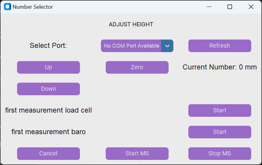
For the interface, I wanted to make sure that the use can do these things:
The first steps of my program can be seen in week 14.
Additionally to this work I added the required functions.
	import customtkinter as tk
	import serial
	from serial.tools.list_ports import comports
	from array import *
	import threading
	import time
	import matplotlib.pyplot as plt
	b = []
	l = []


	ser = serial.Serial(port=None, baudrate=9600)

	class NumberSelector:
		def __init__(self, master):
			self.master = master
			self.number = 0
			font_style = ('Arial', 16)  # Font family and size
			font_style_Buttons = ('Arial', 12)  # Font family and size

			self.title = tk.CTkLabel(master, text="ADJUST HEIGHT")
			self.title.grid(row=1, column=1, columnspan=3, padx=10, pady=10)

			self.port_label = tk.CTkLabel(master, text="Select Port:", font=font_style )
			self.port_label.grid(row=2, column=1, padx=10, pady=10)


			self.available_ports = [port.device for port in comports()]
			if not self.available_ports:
				self.available_ports = ["No COM Port Available"]
			self.selected_port = tk.StringVar(self.master)
			self.selected_port.set(self.available_ports[0])  # Set default port

			self.refresh_button = tk.CTkButton(master, text="Refresh", command=self.refresh_ports, fg_color="#9A6AC8")
			self.refresh_button.grid(row=2, column=3, padx=10, pady=10)

			self.port_menu = tk.CTkOptionMenu(master, variable = self.selected_port, values = self.available_ports,command = connectToBoard, font=font_style)
			self.port_menu.configure(font=font_style_Buttons, fg_color="#9A6AC8")
			self.port_menu.grid(row=2, column=2, padx=10, pady=10)

			self.zero_button = tk.CTkButton(master, text="Zero", command=self.zero, fg_color="#9A6AC8")
			self.zero_button.grid(row=3, column=2, padx=10, pady=10)

			self.label = tk.CTkLabel(master, text="Current Number: 0 mm",font=font_style)
			self.label.grid(row=3, column=3, padx=10, pady=10)

			self.up_button = tk.CTkButton(master, text="Up", command=self.increment, fg_color="#9A6AC8")
			self.up_button.grid(row=3, column=1, padx=10, pady=10)

			self.down_button = tk.CTkButton(master, text="Down", command=self.decrement, fg_color="#9A6AC8")
			self.down_button.grid(row=4, column=1, padx=10, pady=10)

			self.port_label = tk.CTkLabel(master, text="first measurement load cell", font=font_style )
			self.port_label.grid(row=5, column=1, padx=10, pady=10)
			self.load_button = tk.CTkButton(master, text="Start", command=self.loadcellfirst, fg_color="#9A6AC8")
			self.load_button.grid(row=5, column=3, padx=10, pady=10)
			self.port_label = tk.CTkLabel(master, text="first measurement baro", font=font_style )
			self.port_label.grid(row=6, column=1, padx=10, pady=10)
			self.load_button = tk.CTkButton(master, text="Start", command=self.barofirst, fg_color="#9A6AC8")
			self.load_button.grid(row=6, column=3, padx=10, pady=10)


			self.cancel_button = tk.CTkButton(master, text="Cancel", command=self.cancel, fg_color="#9A6AC8")
			self.cancel_button.grid(row=7, column=1, padx=10, pady=10)

			self.ok_button = tk.CTkButton(master, text="Start MS", command=self.start_measurement, fg_color="#9A6AC8")
			self.ok_button.grid(row=7, column=2, padx=10, pady=10)
			self.stop_button = tk.CTkButton(master, text="Stop MS", command=self.stop_measurement, fg_color="#9A6AC8")
			self.stop_button.grid(row=7, column=3, padx=10, pady=10)

		def update_label(self):
			self.label.configure(text="Current Number: {} mm".format(self.number))

		def increment(self):
			self.number += 1
			self.update_label()
			ser.close()
			ser.open()
			ser.write(str.encode("w"))

		def decrement(self):
			self.number -= 1
			self.update_label()
			ser.close()
			ser.open()
			ser.write(str.encode("s"))

		def okay(self):
			selected_port = self.selected_port.get()
			print("Selected COM Port:", selected_port)
			ser.write(str.encode("t"))

			response = ser.readline().decode().strip()  # Read the response from the serial port
			try:
				float_value = float(response)
				print("Load Cell First Measurement:", float_value)  # Print or use the float value as needed
				l.append(float_value)  # Append the float value to the list l
			except ValueError:
				print("Received data is not a valid float:", response)


		def zero(self):
			self.number = 0
			self.update_label()

		def cancel(self):
			 self.master.destroy()  # Close the window

		def refresh_ports(self):

			print("Before refresh - selected port:", self.selected_port.get())
			print("Before refresh - available ports:", self.available_ports)
			self.available_ports = [port.device for port in comports()]
			if not self.available_ports:
				self.available_ports = ["No COM Port Available"]
			self.port_menu.configure(variable=self.selected_port, values=self.available_ports)  # refreshes list
			print("After refresh - selected port:", self.selected_port.get())
			print("After refresh - available ports:", self.available_ports)

		def loadcellfirst(self):
			ser.close()
			ser.open()
			ser.write(str.encode("l"))

			response = ser.readline().decode().strip()  # Read the response from the serial port
			try:
				float_value = float(response)
				print("Load Cell First Measurement:", float_value)  # Print or use the float value as needed
				l.append(float_value)  # Append the float value to the list l
			except ValueError:
				print("Received data is not a valid float:", response)

		def barofirst(self):
			ser.close()
			ser.open()
			ser.write(str.encode("b"))
			response = ser.readline().decode().strip()  # Read the response from the serial port
			try:
				float_value = float(response)
				print("Barometer First Measurement:", float_value)  # Print or use the float value as needed
				b.append(float_value)  # Append the float value to the list b
			except ValueError:
				print("Received data is not a valid float:", response)

		def start_measurement(self):
			global measurement_flag
			measurement_flag = True
			self.ok_button.configure(state=tk.DISABLED)  # Disable Start MS button
			self.stop_button.configure(state=tk.NORMAL)  # Enable Stop MS button

			# Start the measurement loop in a separate thread
			threading.Thread(target=self.measure_values).start()

		def stop_measurement(self):
			global measurement_flag
			measurement_flag = False
			self.ok_button.configure(state=tk.NORMAL)  # Enable Start MS button
			self.stop_button.configure(state=tk.DISABLED)  # Disable Stop MS button
			self.create_graph()  # Call the function to create the graph
			print(b)

		def create_graph(self):
			plt.figure(figsize=(8, 6))
			plt.plot(b, label='Barometer Data')
			plt.plot(l, label='Load Cell Data')
			plt.xlabel('Force/Pressure')
			plt.ylabel('Time')
			plt.title('Measurement Data')
			plt.legend()
			plt.show()

		def measure_values(self):
			while measurement_flag == True:  # Loop until measurement flag is False
				print("in while lop")
				ser.close()
				ser.open()
				ser.write(str.encode("r"))
				response_b = ser.readline().decode().strip()  # Read the response from the serial port
				try:
					float_value_b = float(response_b)
					b.append(float_value_b)  # Append the float value to the list b
				except ValueError:
					print("Received data for barometer is not a valid float:", response_b)
				time.sleep(0.1)

				ser.close()
				ser.open()
				ser.write(str.encode("c"))
				response_l = ser.readline().decode().strip()  # Read the response from the serial port
				try:
				 float_value_l = float(response_l)
				 l.append(float_value_l)  # Append the float value to the list l
				except ValueError:
				 print("Received data for load cell is not a valid float:", response_l)

				time.sleep(0.1)


	def delay(self):
		import time
		time.sleep(0.1)


	def connectToBoard(port):
		ser.port = port
		ser.close()
		ser.open()
		ser.flush()


	def main():
		root = tk.CTk()
		root.title("Number Selector")
		app = NumberSelector(root)

		root.mainloop()

	if __name__ == "__main__":
		main()
This program created this Interface.
To connect it to the board, I uploaded this code to the PCB.
	#include "SoftwareSerial.h"
#if defined(ESP8266)|| defined(ESP32) || defined(AVR)

#endif

#define stepPin 16
#define dirPin 13
#define enPin 11
const int basensorDataPin = 2;
const int basensorClockPin = 3;
const int lCsensorDataPin = 5;
const int lCsensorClockPin = 4;

char incomingState;


const int rx_pin = 6;
const int tx_pin = 7;

const int stepsPerRevolution = 200;
char incomingState;
SoftwareSerial mySerial(rx_pin , tx_pin);

void setup() {
  pinMode(basensorDataPin, INPUT_PULLUP);
  pinMode(basensorClockPin, OUTPUT);
  pinMode(lCsensorDataPin, INPUT_PULLUP);
  pinMode(lCsensorClockPin, OUTPUT);
  // Initialize the clock pin to LOW
  digitalWrite(basensorClockPin, LOW);
  digitalWrite(lCsensorClockPin, LOW);

  pinMode(stepPin, OUTPUT);
  pinMode(dirPin, OUTPUT);
  pinMode(rx_pin, INPUT);
  pinMode(tx_pin, OUTPUT);
  mySerial.begin(9600);
  mySerial.println();

  pinMode(enPin, OUTPUT);

}

void loop() {
  digitalWrite(enPin, LOW);


  while (mySerial.available() > 0) {
  incomingState = mySerial.read();

  if (incomingState == 'w') {
    digitalWrite(dirPin, HIGH);
    mySerial.println("Message received");
    stepMotor(); // Step the motor
  } else if (incomingState == 's') {
    digitalWrite(dirPin, LOW);
    mySerial.println("Message received");
    stepMotor(); // Step the motor
  }

  if (incomingState == 'b'){
    int sensorValue = readSensorDataBa();
    long mappedValue = map(sensorValue, 0, 32767, 0, 65535);

    float calib = (mappedValue-6144)*0.000193673;
    mySerial.println(calib);
    // Add a delay for readability (adjust as needed for your sensor's data rate)
    delay(100);
  }
  if (incomingState == 'l'){
    int sensorValue = readSensorDataLC();
    long mappedValue = map(sensorValue, 0, 32767, 0, 65535);

    float calib = (mappedValue+212)*0.1375;
    mySerial.println(calib);

    delay(100);
   }


  if (incomingState == 'r'){
    int sensorValue = readSensorDataBa();
    long mappedValue = map(sensorValue, 0, 32767, 0, 65535);

    float calib = (mappedValue-6144)*0.000193673;
    mySerial.println(calib);

    delay(100);
   }
  if (incomingState == 'c'){
 int sensorValue = readSensorDataLC();
  long mappedValue = map(sensorValue, 0, 32767, 0, 65535);

  float calib = (mappedValue+212)*0.1375;
  mySerial.println(calib);
  delay(100);
  }
  }
}

void stepMotor() {
  for(int x=0;x < 200*2.5 ; x++){
  digitalWrite(stepPin, HIGH);
  delayMicroseconds(700);
  digitalWrite(stepPin, LOW);
  delayMicroseconds(700);
}}

int readSensorDataBa() {
  int data = 0;

  const int bitLength = 16;

  for (int i = 0; i < bitLength; i++) {
    // Pulse the clock pin
    digitalWrite(basensorClockPin, HIGH);
    delayMicroseconds(20);
    digitalWrite(basensorClockPin, LOW);
    delayMicroseconds(20);


    int bit = digitalRead(basensorDataPin);


    data <<= 1;
    data |= bit;

  }

  return data;
}

int readSensorDataLC() {
  int data = 0;


  const int bitLength = 16;

  for (int i = 0; i < bitLength; i++) {

    digitalWrite(lCsensorClockPin, HIGH);
    delayMicroseconds(20);
    digitalWrite(lCsensorClockPin, LOW);
    delayMicroseconds(20);


    int bit = digitalRead(lCsensorDataPin);

    data <<= 1;
    data |= bit;

  }

  return data;
}
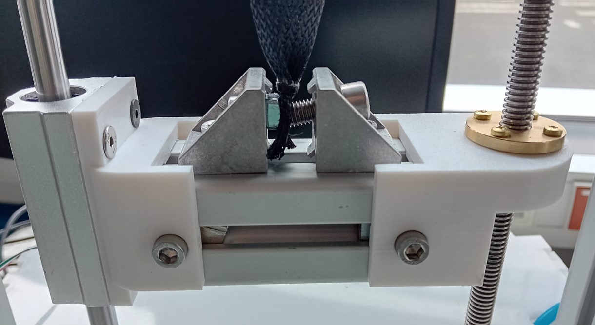
Result
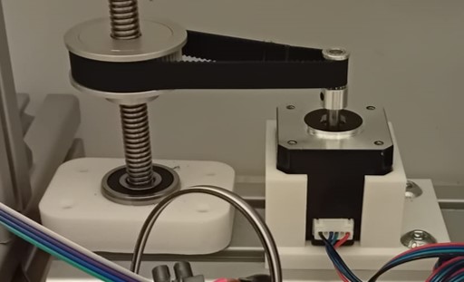
I finished the linear system with the use of the a pulley system, that connected the stepper motor and the threaded shaft (gear ratio 2.5:1).
I was able to control the length adjustment with the program.
I was also able to get first measurements.
I was also able to get the measurements and create a graph afterwards.
Evaluation
For Fabacademy there were a few points that needed to be included and were required:
I was able to achieve all these requirements.
Additionally, I formulated some further requirements for my project:
There are still some points to discuss.
The current barometric sensor is unable to test the maximum force that the artificial muscle can generate. Additionally, the full potential of the load cell is not being utilized.
Although the frame showed no visible problems with oscillation during measurements, a more thorough evaluation is needed. Inducing artificial oscillations can help ensure the frame's stability under dynamic loads.
The entire machine can be produced for under 300 €, classifying it as a low-budget option for a material tester.
The materials of the frame are designed to withstand a groove pull-out force of 2500 N. With the load cell measuring up to 500 N, this provides a safety factor of 5, which should be sufficient to ensure structural integrity.
The current response time for measurements is 0.1 s.
License

I chose the creative common license for my project to allow everyone the freedom to build my machine if they wish. This license ensures that anyone can use, modify, and distribute the design, making it accessible for all who are interested.
With their website it easy to choose the right license and get one.
Artificial Muscle Tester © 2024 by Sophia Felcicia Salome Döring is licensed under CC BY 4.0.
Achknowledgements
I would like to thank our instructor, Ahmed Belal Abdellatif, for his support and teaching during Fab Academy, as well as for his assistance with the final project. I am also grateful to my fellow Fab Academy students, Frauke Waßmuth, Bianca Guimaraes, and Ece Öner, for being such awesome teammates. We faced both great and stressful times together, and their camaraderie made the experience truly memorable.
Additionally, I would like to extend my thanks to Roland Grichnik, Leen Nijim, and Aaron Hinkle for their advice and help during Fab Academy, and for sharing their experiences from their own Fab Academy years.
I am also thankful to Gleb Byvaltsev, Fransceska Collaku, Simon Wimmer, Manav Thakkar, and Ibin Roshan for their moral support and assistance with manual fabrication.