Output Devices
Assignments
- Group Assignment
- measure the power consumption of an output device
- Individual Assignment
- add an output device to a microcontroller board you've designed, and program it to do something
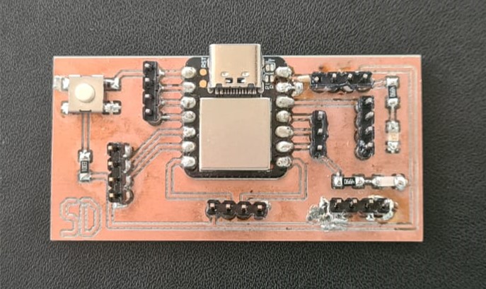
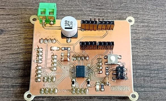
Printed Circuit Boards
For this week's assignment, I used the board I produced in week 4 and week 8 to control the output device I am using for my final project a stepper motor.
Stepper Motor and Motor Driver
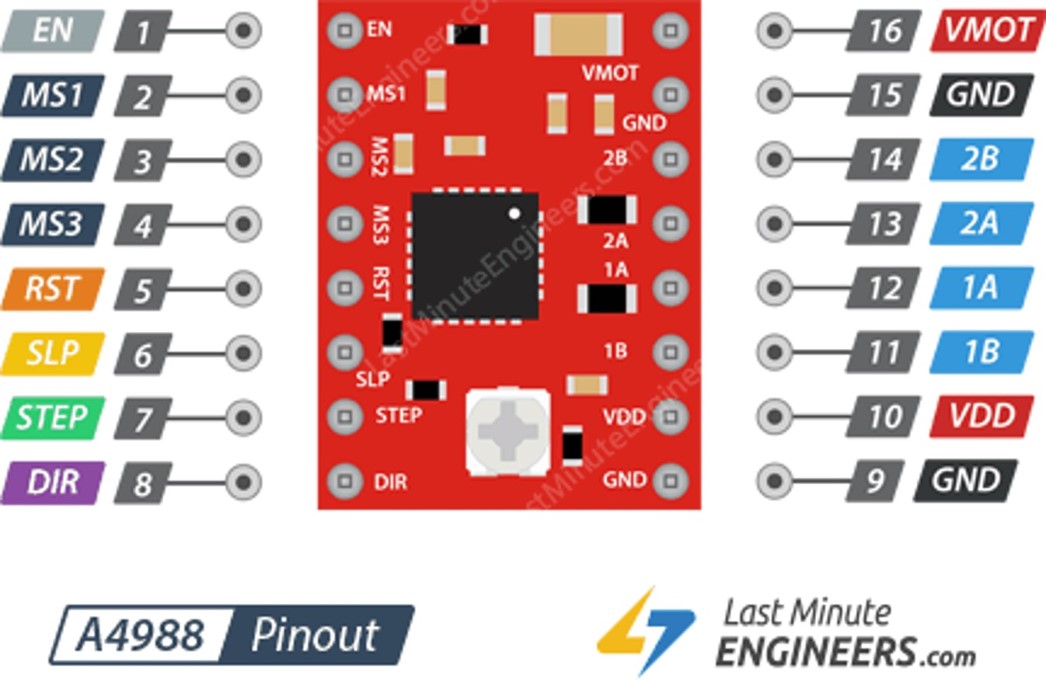
In week 6 I have already worked with the Nema 17 and the a4988 motor driver. I explained both of the components a little bit in the week, but I want to go more into detail in this week.
Motor Driver Adjustments
Adjusting the Potentiometer
The potentiometer on the A4988 module allows you to adjust the motor current limit. This limit determines the maximum amount of current that can flow through each coil of the stepper motor. By adjusting this limit, you can control the amount of torque produced by the motor and prevent it from drawing excessive current, which could lead to overheating or damage to the motor and driver.
The potentiometer adjusts the reference voltage, which in turn adjusts the motor current limit according to the formula:
$${V_{ref} = 8* I_{max} * R_{CS}}$$
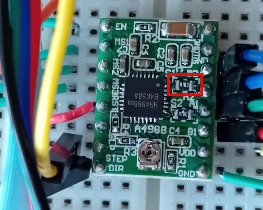
According to the data sheet of the stepper motor I am using, the maximum current is 1,5 A. To know the resistance you have to look into the a4988 data sheet or the driver itself. The resistor has the number R100, which means a resistance of 10 Ohm (see here for the translator). Therefore the needed reference voltage is 1.2 V.
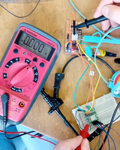
The a4988 has a little screw for adjusting the resistance. The best way to measure the voltage and adjust the screw with a screwdriver.
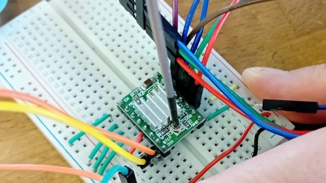
When measuring the voltage for my A4988, I found it to be at 0.0 V, which was quite surprising. Even after adjusting the screw, there was no change in the value. Upon investigation, it was discovered that the motor driver was defective. After replacing the motor driver, I was able to adjust the voltage to 1.2 V.
The adjustment of the potentiometer is effective for normal stepping, but it may not be optimized for microstepping due to differences in current supply.
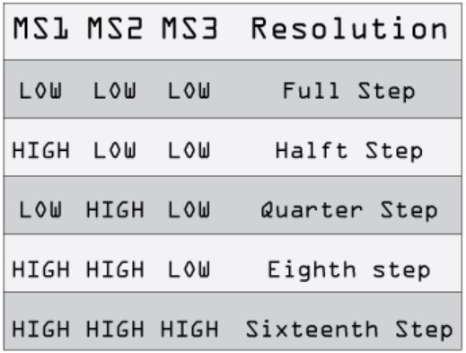
Microstepping
The motor driver a4988 has the possibility to use microstepping in your stepper motor. Microstepping is a technique used in stepper motors to achieve smoother motion and finer positioning resolution compared to traditional full-step or half-step methods.
In a stepper motor, each step corresponds to a discrete angular rotation of the motor shaft. For instance, in a standard full-step motor, the rotor moves from one full step to the next, typically 1.8 degrees per step for a standard 200-step motor.
Microstepping breaks down these discrete steps into even smaller increments, allowing for finer control of the motor's position and smoother motion. This is achieved by using intermediate current levels between the coils of the motor. By energizing the coils in a controlled sequence and varying the current levels, the motor's rotor can be positioned at positions between the traditional full steps.
In microstepping, the current flowing through each coil of the stepper motor is controlled more precisely.
This is typically achieved by using pulse-width modulation (PWM) to control the amount of current supplied to each coil.
But there are some disadvantages of microstepping. In some cases, microstepping can lead to reduced torque output compared to full-step operation, particularly at higher microstep resolutions. This reduction in torque can be significant, especially at higher speeds or when the motor is under load. As a result, microstepping may not be suitable for applications requiring high torque output. Microstepping can increase heat generation in the stepper motor and driver electronics due to the continuous current switching required to achieve intermediate positions. This heat buildup can lead to thermal issues, particularly in applications where the motor operates for extended periods or under high load conditions. Adequate heat dissipation measures may be necessary to prevent overheating and ensure reliable operation.
Driving the Stepper Motor
Int he following picture you can see the circuit used for driving the stepper motor.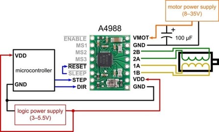
For driving the stepper motor, I used this code in the Arduino IDE.
	#define stepPin 10
	#define dirPin 8

	void setup() {
	// Sets the two pins as Outputs
	pinMode(stepPin,OUTPUT);
	pinMode(dirPin,OUTPUT);
	}
	void loop() {
	digitalWrite(dirPin,HIGH);
	for(int x = 0; x < 800; x++) {
		digitalWrite(stepPin,HIGH);
		delayMicroseconds(800);
		digitalWrite(stepPin,LOW);
		delayMicroseconds(800);
	}
	delay(1000); // One second delay


	}
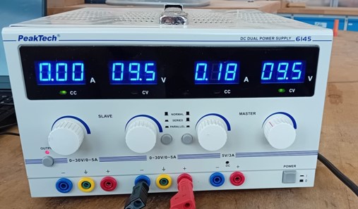
To regulate the supplementary voltage supply for the stepper motor, I utilized a bench power supply. Referencing the datasheet, it stipulated that the Nema 17 motor's voltage range should ideally fall between 8 to 35 V. I applied 9.5 V to the motor driver.
Communication with the Stepper Motor
In the next iteration of the code, I tried to control the direction of the stepper motor with my computer via the serial monitor.
#define stepPin 1
#define dirPin 2
#define enablePin 3


const int stepsPerRevolution = 200;  // change this to fit the number of steps per revolution of your motor
char incomingState;

void setup() {
	Serial.begin(9600);  // initialize serial communication at 9600 baud
	pinMode(stepPin, OUTPUT);
	pinMode(dirPin, OUTPUT);
	pinMode(enablePin, OUTPUT);
	digitalWrite(enablePin, LOW); // Enable the stepper motor
}

void loop() {
	while (Serial.available() > 0) {
	incomingState = Serial.read();

	if (incomingState == 'w') {
		digitalWrite(dirPin, HIGH); // Set direction to move forward
		stepMotor(); // Step the motor
	} else if (incomingState == 's') {
		digitalWrite(dirPin, LOW); // Set direction to move backward
		stepMotor(); // Step the motor
	} else {
		if (incomingState != '\n' && incomingState != '\r') {
		Serial.print("Unknown message '");
		Serial.print(incomingState);
		Serial.println("'. Use 'w' or 's' to control direction.");
		}
	}
	}
}

void stepMotor() {
	for(int x=0;x < 200 ; x++){
	digitalWrite(stepPin, HIGH);
	delayMicroseconds(10000); // Adjust this delay as needed
	digitalWrite(stepPin, LOW);
	delay(5); // Adjust this delay as needed
}}

}
Power Supply
With the bench power supply, you can calculate the power supply as the machine adjusts the current needed for the motor. The Power supply can be calculated as follows:
$${P = V * I}$$Where V ist the voltage and I is the current. The equation leads to a power supply of 1,71 Watt.
Upon examining the required current, it appears surprisingly low, particularly when considering the specified current needed per phase according to the datasheet, which is 1.5 A. This indicates a total current requirement of 3 A for a two-phase stepper motor.