Embedded Programming
Assignments
- Group Assignment
- browse through the data sheet for your microcontroller
- compare the performance and development workflows for other architectures
- Individual Assignment
- write a program for a microcontroller development board that you made, to interact (with local input &/or output devices) and communicate (with remote wired or wireless devices)
Data Sheet of the microcontroller
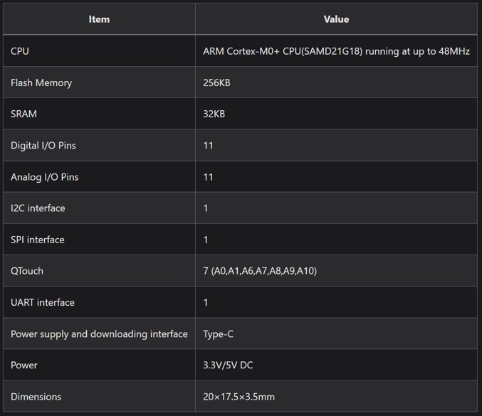
The microcontroller we all used in the week of electronic production is an ATSAMD21-G18A-MU, which is embedded in mini board SAMD-21 from Seeduino. Every microcontroller needs a data sheet, that described everything important for the user. It is a comprehensive document that provides detailed information about the microcontroller's specifications, features, and electrical characteristics. The data sheet of our microcontroller can be found online (see here). There are several things we looked into:
| Feature | Information | ATSAMD21-G18A-MU |
|---|---|---|
| Functional Block Diagram | Architecture, Pins, and functions of the Pins | Look at the picture below |
| PinOut / Pin Multiplexing | Pin numbering and names, pin types, special functions and voltage | Look at the picture below |
| Power supply | Power supply to microcontroller, supply of pins | Voltage is 1.62V to 3.63V |
| Memories | Flash memory size, RAM size, EEPROM (Electrically Erasable Programmable Read-Only Memory), computing velocity | 256KB Flash, 32KB SRAM, 64 KB peripherals, 32-bit |
| Electrical Characteristics | Clock frequency, current consumption, operating temperature range, noise margin, oscillator frequency range | 48 MHz; Consumption in IDLE mode 1.17 mA in Active IN 10.3 mA, -40°C to 85°C etc. |
| Packaging Information | Package size, pin size + distance, thermal resistance of package, soldering profile | 1.2 x 9 x 9 mm package, 0.25 mm pin width, 0.5 mm distance, 32°C/W, max. soldering temperature of 260°C |
| Serial Communication Interface | Available communication protocols | I2C, USART, SPI |
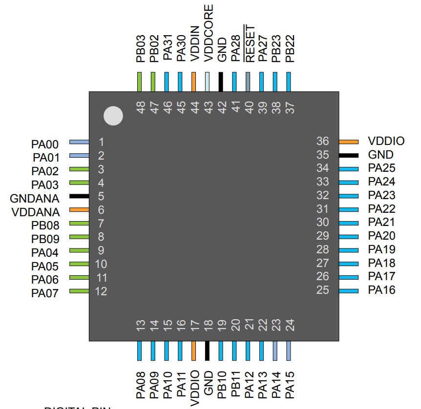
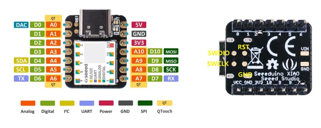
As the microcontroller is seamlessly integrated into the Seeduino board, it's important to highlight key details and functionalities.
Pinout diagram is a visual representation of the microcontroller's package and pin assignments and the pin function is a detailed description of each function of the pins.
C++ (Arduino) and Circuit Python
For the group assignment, we took a closer look into the different possibilities for programming the microcontroller. With the help of the wiki page of the board, that includes a description to change the programming language and to upload the bootloader. Everything regarding this assignment can be found on the webpage (see here).
In reflection to this assignment, the question stays: What should I use in the future: C++ or Circuit Python? For now, I decided to stay with the Arduino IDE used language, as I already have some experience with it.
Interacting with Input and Output Device
In Week 4's assignment, I delved into the interaction between a simple input device (button) and an output device (LED). The configuration and installation procedures for working with the Seeeduino board in the Arduino IDE were detailed in that week's assignment (see here).
Building on that foundation, this week's focus shifted towards developing input and output devices essential for my final project. I initiated the process by working on a stepper motor.
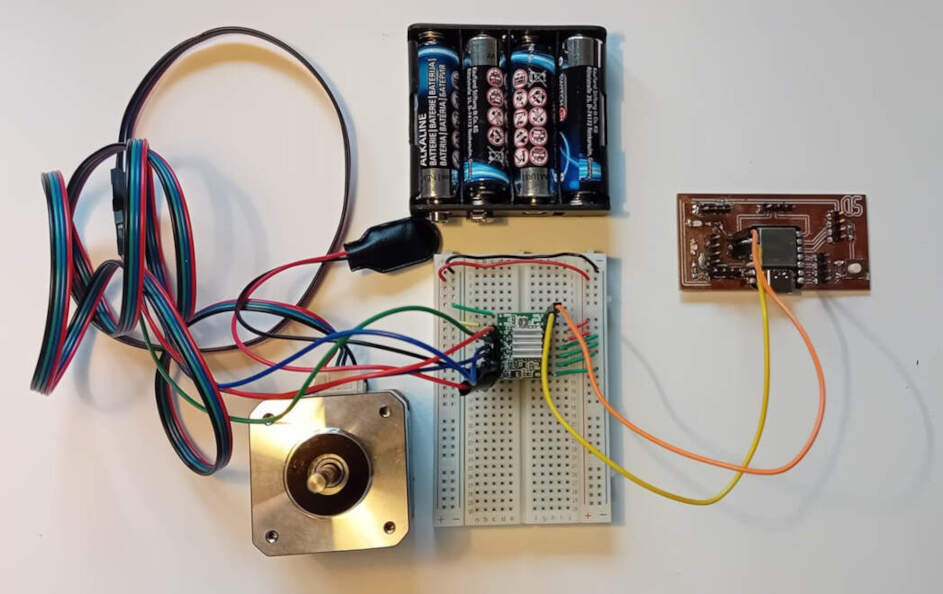
In addition to my PCB, the components employed included various jumper wires, a breadboard, a 6V battery pack, a stepper motor driver chip, and the stepper motor itself.
Stepper Motor
A stepper motor is a type of brushless DC electric motor that divides a full rotation into a number of equal steps. It's designed to move in discrete steps, allowing precise control over position without the need for feedback mechanisms like encoders in some cases. Stepper motors find applications in various fields, including robotics, 3D printing, CNC machines, and automation systems.
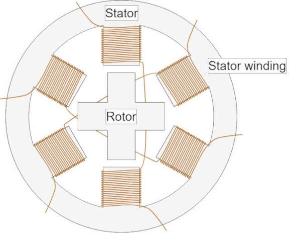
The basic structure of a stepper motor consists of a rotor (the moving part) and a stator (the stationary part). The rotor typically has a shaft that can be connected to the load to be moved. The stator contains multiple coils of wire, and these coils are energized in a specific sequence to create a magnetic field. The number of coils and their arrangement determine the motor's step resolution
Stepper motors move in steps, and the step angle is the angle by which the rotor rotates for each step. For example, a motor with a step angle of 1.8 degrees will have 200 steps for a full revolution (360 degrees/1.8 degrees per step).
Stepper motors are known for their simplicity, reliability, and ease of control.They provide precise position control without the need for an external feedback system in many applications. They can maintain their position when stationary, as they do not require continuous power to hold a position.They might not be as efficient as some other motor types, especially at high speeds. Torque decreases with increasing speed.
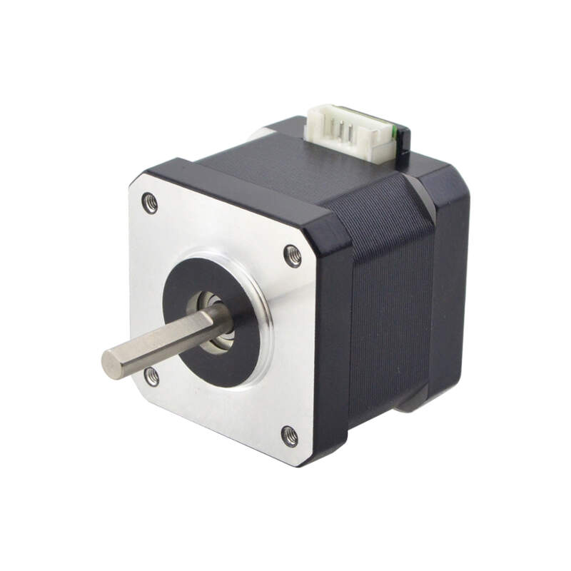
For my application i used a NEMA 17 stepper motor. It is part of the NEMA standard, which defines the physical dimensions and mounting configurations for stepper motors. The "17" in NEMA 17 represents the motor's frame size, which is 1.7 x 1.7 inches or 43.2 x 43.2 mm. In a bipolar configuration, the motor has two coils per phase, and the direction of current flow can be reversed to change the magnetic polarity. The stepper motor has a step angle of 1.8 degrees per step, resulting in 200 steps for a full revolution. These are typically used in smaller applications, such as 3D printers, CNC machines, and robotics.
Stepper Motor Driver Chip
Stepper motor driver chips play a crucial role in controlling and powering stepper motors. These chips interface between a microcontroller or other control system and the stepper motor, ensuring that the motor receives the correct signals and power to move in a controlled manner. They have several functions:
- Control Signal Interpretation: Stepper motor drivers take input signals from a control system, typically in the form of pulses or step and direction signals.
- Current Regulation: Driver chips regulate the current flowing through the motor coils to ensure optimal performance and prevent overheating.
- Pulse Generation: Driver chips generate the necessary pulses to control the motor, determining its speed and direction.
- Protection Features: Some driver chips include protection features like overcurrent protection, thermal shutdown, and short-circuit protection.
- Current Decay Modes: Driver chips may offer different current decay modes, affecting performance and power consumption.
- Voltage Regulation: Stepper motor driver chips often have built-in voltage regulators for a stable power supply to the motor.
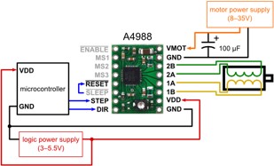
I used A4988 stepper motor driver module with heat sink, which is a DMOS microstep driver with converter and overcurrent protection. It is suitable for driving stepper motors under 8V to 35V with a 2A current.
Application
I started by simply using the direction and step pin and connect them to my PCB (pin 8 and 10 on my microcontroller). I wrote a simple code for the stepper motor:
void setup() {
	pinMode(8, OUTPUT);
	pinMode(10,OUTPUT);
	digitalWrite(8, HIGH);
}

void loop() {
	digitalWrite(10,HIGH);
	delay(1);
	digitalWrite(10,LOW);
	delay(100);
}
Pin 8 is connected to the direction pin of the stepper motor driver. When the signal is LOW, the motor moves clockwise; when it is HIGH, the motor moves counterclockwise. Using Pin 10, you can control the step. Instead of specifying the exact number of steps to move, you can indicate a duration, such as 0.1 seconds, during which the stepper motor moves.
During my first attempt at running the code, I encountered an issue where the stepper motor failed to move, leading me to scrutinize the circuit and pin connections for any errors. After multiple checks, I confirmed that the circuit and pin connections were accurate. However, the motor wasn't entirely motionless; rather, it struggled to overcome the torque, suggesting an underlying problem. To investigate further, I tested another stepper motor from my lab, and it operated successfully. This led me to suspect that the issue lay with the initial stepper motor. Roland Grichnik, a former Fabacademy student, offered a valuable insight – he mentioned encountering a problem with a batch of stepper motors due to incorrect wiring in the connection cable. Specifically, the two center cables needed to be reversed.
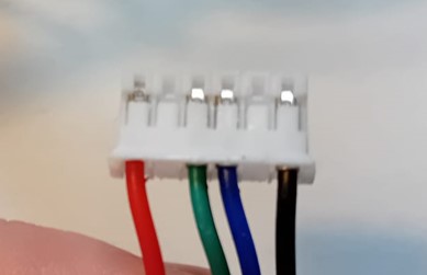
Following this advice, I cautiously addressed the potential wiring problem. I carefully removed the two cables from the connector by bending the plastic noses and disconnecting them. Afterward, I switched the positions of the cables, ensuring that the two center cables were correctly oriented. Finally, I pressed the cables back into the connector.
After this, code and stepper motor were working correctly.
Serial Communication
Before starting the communication with the serial monitor of the Arduino IDE, I tried to us the button as a switch:
const int buttonPin = 0;     // the number of the pushbutton pin
const int ledPin =  8;
int ledPinState = 0;     // the number of the LED pin

int buttonState = 0;         // variable for reading the pushbutton status

void setup() {
  // initialize the LED pin as an output:
  pinMode(ledPin, OUTPUT);
  // initialize the pushbutton pin as an input:
  pinMode(buttonPin, INPUT);
}

void loop() {
  // read the state of the pushbutton value:
  buttonState = digitalRead(buttonPin);

  // check if the pushbutton is pressed. If it is, the buttonState is HIGH:
  if (buttonState == LOW) {
    if (ledPinState == 0){
      digitalWrite(ledPin, HIGH);
      ledPinState = 1;
      buttonState = digitalRead(buttonPin);

    }
    else{
      digitalWrite(ledPin, LOW);
      ledPinState = 0;
      buttonState = digitalRead(buttonPin);

    }
  }
}
In response to the microcontroller intermittently failing to register button presses, I conducted thorough research to diagnose the issue and find a resolution. It became evident that the problem stemmed from the way the code was checking and managing the button state. To rectify this issue, I introduced a debounce delay into the code. This delay is implemented to counteract false readings triggered by the button, contributing to a more reliable and consistent button press recognition. The debounce delay has proven effective in mitigating the problem, resulting in improved performance of the button detection mechanism.
const int buttonPin = 0;   // Change to the actual pin number of your pushbutton
const int ledPin =  8;
int ledPinState = 0;
int buttonState = HIGH;
int lastButtonState = HIGH;
unsigned long lastDebounceTime = 0;
unsigned long debounceDelay = 50;

void setup() {
	pinMode(ledPin, OUTPUT);
	pinMode(buttonPin, INPUT);
}

void loop() {
	int reading = digitalRead(buttonPin);

	if (reading != lastButtonState) {
	lastDebounceTime = millis();
	}

	if ((millis() - lastDebounceTime) > debounceDelay) {
	if (reading != buttonState) {
		buttonState = reading;

		if (buttonState == LOW) {
		ledPinState = 1 - ledPinState; // Toggle the state
		digitalWrite(ledPin, ledPinState);
		}
	}
	}

	lastButtonState = reading;
}
The subsequent step involved reporting the LED state to the Serial Monitor by printing either 'ON' or 'OFF' messages.
const int buttonPin = 0;   // Change to the actual pin number of your pushbutton
const int ledPin =  8;
int ledPinState = 0;
int buttonState = HIGH;
int lastButtonState = HIGH;
unsigned long lastDebounceTime = 0;
unsigned long debounceDelay = 50;

void setup() {
	pinMode(ledPin, OUTPUT);
	pinMode(buttonPin, INPUT);
	Serial.begin(9600);
}

void loop() {
	int reading = digitalRead(buttonPin);

	if (reading != lastButtonState) {
	lastDebounceTime = millis();
	}

	if ((millis() - lastDebounceTime) > debounceDelay) {
	if (reading != buttonState) {
		buttonState = reading;

		if (buttonState == LOW) {
		ledPinState = 1 - ledPinState; // Toggle the state
		digitalWrite(ledPin, ledPinState);
		if (ledPinState == 1){
		Serial.println("ON");
		}
		else{Serial.println("OFF");}
		}
	}
	}

	lastButtonState = reading;
}
To open the serial monitor press Ctrl + Shift + M or go to "Tools" and click on "Serial Monitor".
Note: Sometimes you have to close the Serial Monitor again to be even able to upload code to your microcontroller again.
The last step was to control the state of the LED with a message send to the serial monitor (0 for "OFF" and 1 for "ON").
int ledPin = 8;
char incomingState;

void setup() {
	pinMode(ledPin, OUTPUT);
	Serial.begin(9600);
}

void loop() {
	while (Serial.available() > 0) {
	incomingState = Serial.read();

	if (incomingState == '1') {
		digitalWrite(ledPin, HIGH);   // turn the LED on
		Serial.println("Message '1' received. Turning LED on.");
	} else if (incomingState == '0') {
		digitalWrite(ledPin, LOW);   // turn the LED off
		Serial.println("Message '0' received. Turning LED off.");
	} else {
		if (incomingState != '\n' && incomingState != '\r') {
		Serial.print("Unknown message '");
		Serial.print(incomingState);
		Serial.println("'. Use '1' and '0' to turn LED on and off.");
		}
	}
	}
}