System Integration
Assignments
- Design and document the system integration for your final project
System Diagrams

Cable Management
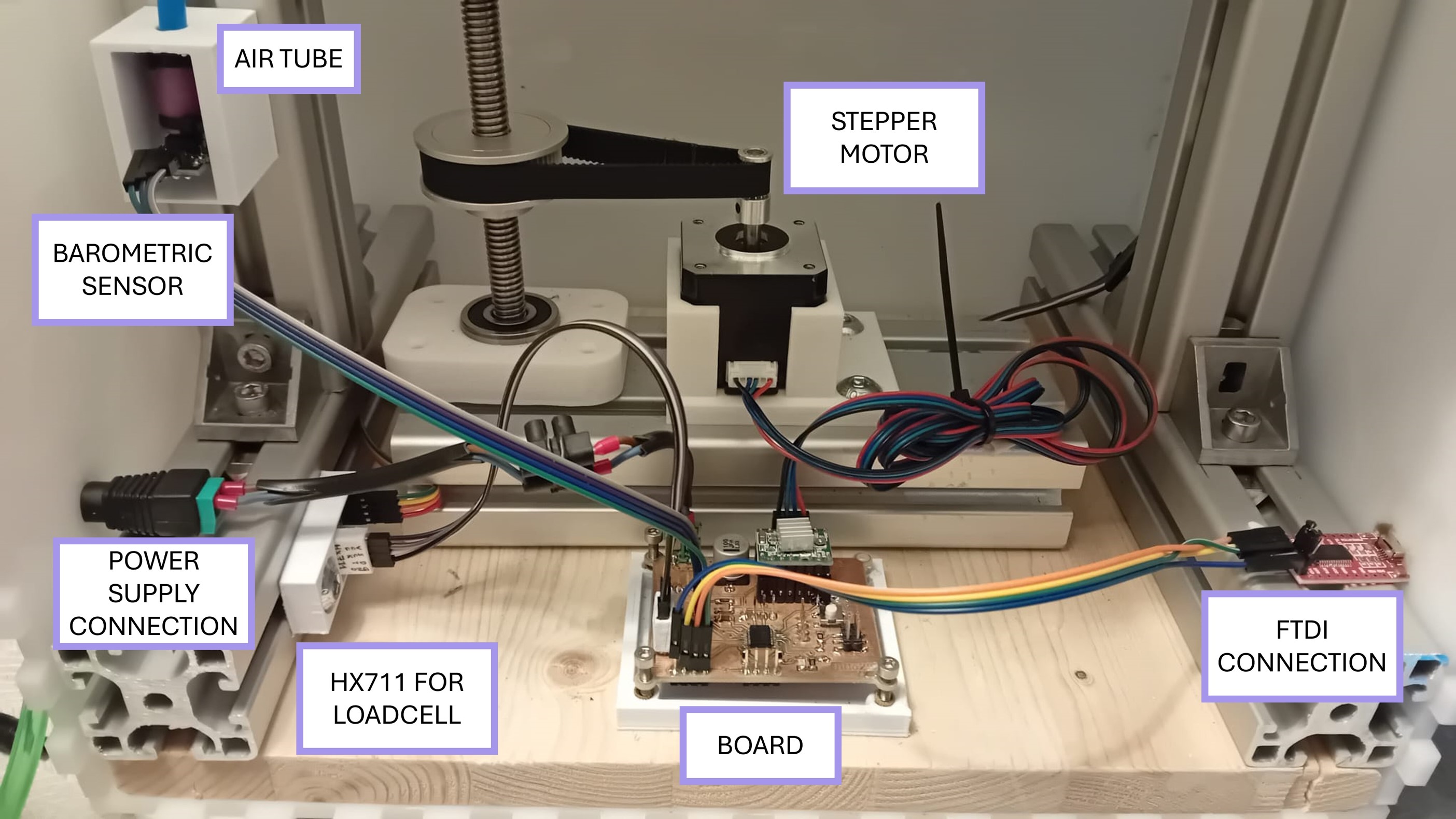
For the cable management it is important to have an overview over the position of the connections on the board.
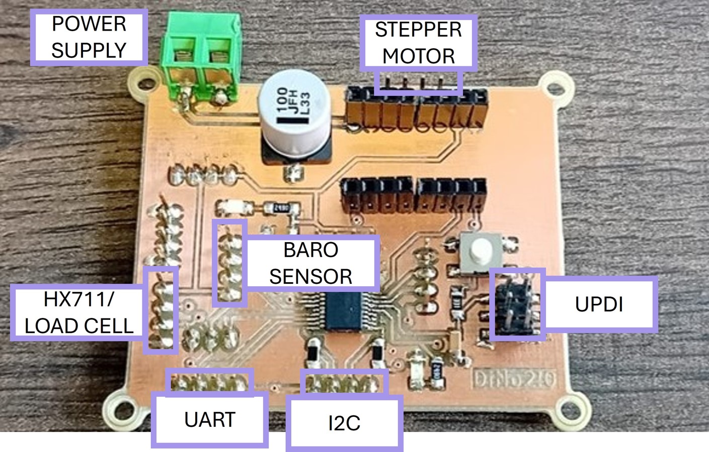
I had to make sure that the cable management in my final project is also encounting the design of the PCB placing sensors and output devices in the enclosure in a way the cable do not inter vine.
Three different output have to go outside of the enclosure:
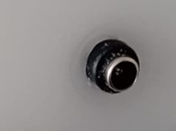
- The FTDI board connection to connect the PCB to the computer
- The Power Supply to connect to the PCB
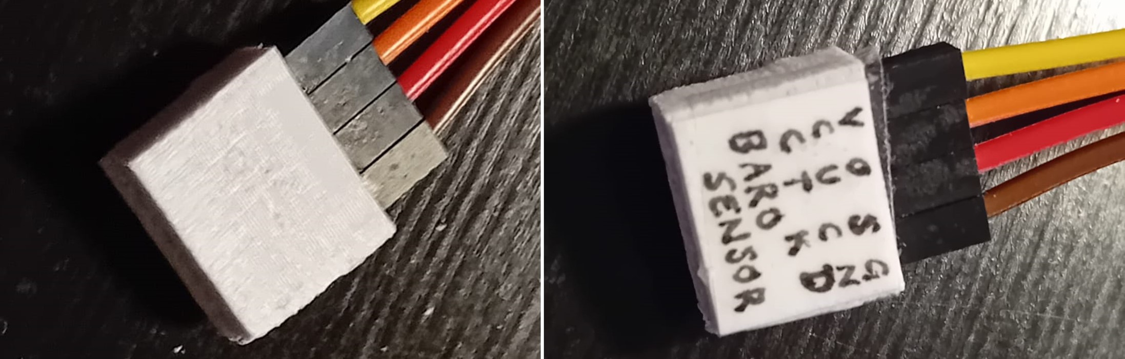
- The tube from the Barometric sensor to the manual pump for pumping the artificial muscle
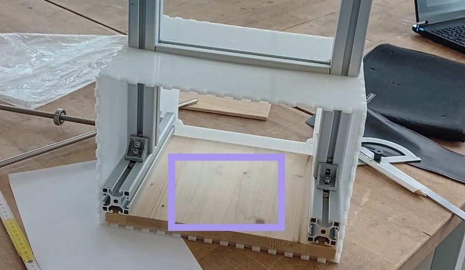
I lasercut the correct holes for the output into the enclosure made of POM. Additionally, the cables of the load cell had to go out side the enclosure, but it is possible to arrange the cable inside the slides of the aluminum profiles.
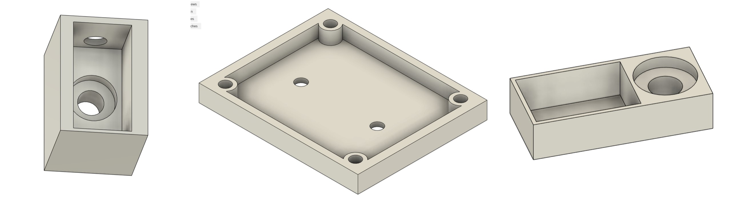
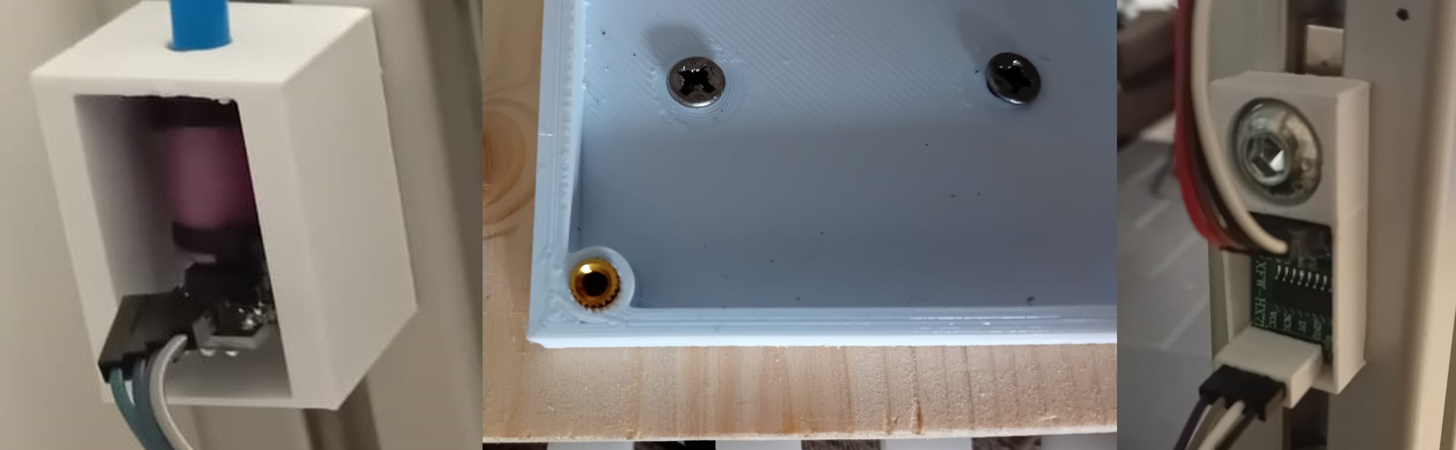
Additionally, I design and 3D printed enclosures and position holders for the PCB, HX711, and the barometric sensor.
Additionally, I made connection parts for the jumper cables and the PCB/Device.
With these components and as the correct psition of the frame/bottom, I achieved a relatively good cable management.