Computer Aided Design
In this week we were introduced to Computer Aided Design. Motivated to learn 2D and 3D modelling, parametric design, logical operation in design, and important after design steps.
Assignments
- Model a possible final project
- compress image and videos
- post your design files on your webpage
OBS Studio
To ensure optimal capture of my work, I customized the settings in OBS Studio.
Initially, the resolution was insufficient to adequately showcase my activities in the Inkscape
file. Additionally, since high frame rates are unnecessary for documentation purposes, I adjusted
FPS rate to a lower frequency.
This adjustment optimizes resources without compromising the quality of the recording.
The following steps were taken to enhance the resolution and decrease the FPS rate:

- Open OBS Studio and navigate to the control panel
- Click on "Settings"
- Under the "Video" tab, locate the "Base (Canvas) Resolution" and "Output (Scale) Resolution" settings
- Increase both the "Base (Canvas) Resolution" and "Output (Scale) Resolution" to achieve a higher-quality output
- Decrease the Frames Per Second (FPS) value
Modelling
2D Modelling
In 2D modelling two different concepts in the design and programs, raster and vector based. Raster based design and programs work with a grid of squares, each of them containing a color value, also called pixels. Photos are the most common known form of a raster 2D model. Programs for working and manipulating raster models are Adobe Photoshop or GIMP.
Vector based designs are 2D models, visualized by underlying mathematical formulas and paths to define shapes and objects. These are incredible useful tools for applications like diagrams and animations as there is not a lost of details when zooming in and out. Programs for working with vector files are Inkscape and Illustrator.
In this week, I tried to learn GIMP and Inkscape to work with raster and vector graphics.
Raster modelling
I decided to get started with GIMP, as it is an open-source program, that I can use freely even after university. To begin with GIMP I followed a tutorial from Kevin Stratvert (see here).
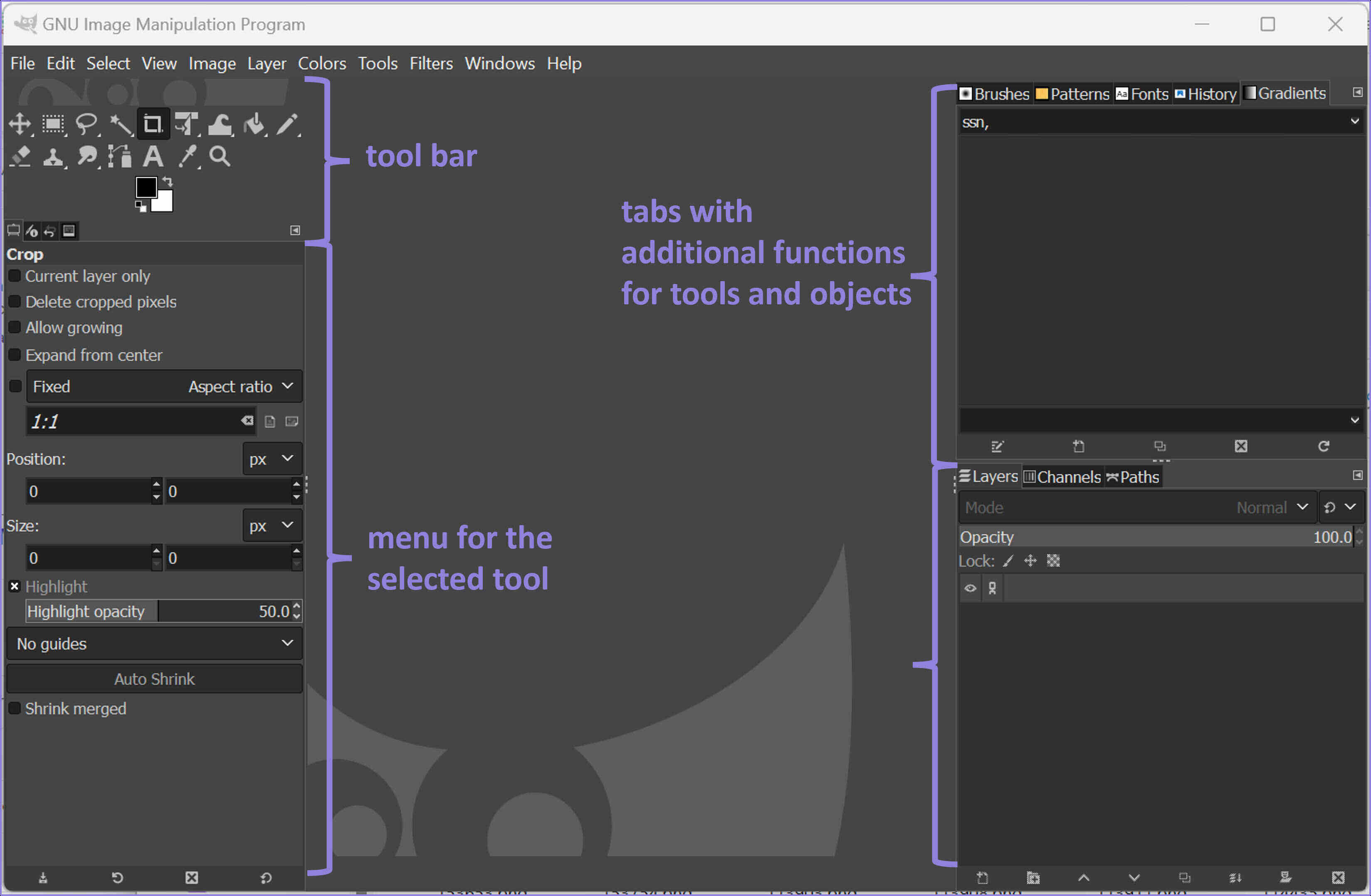
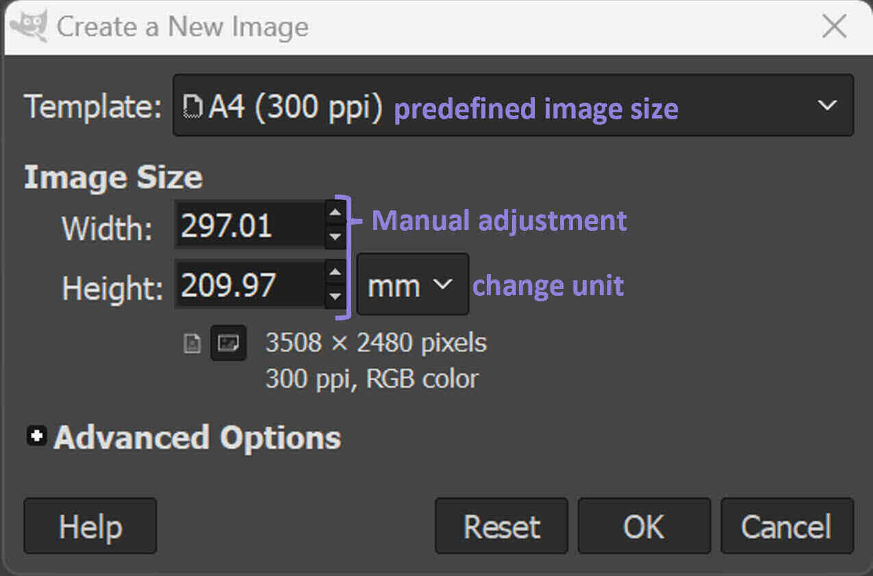
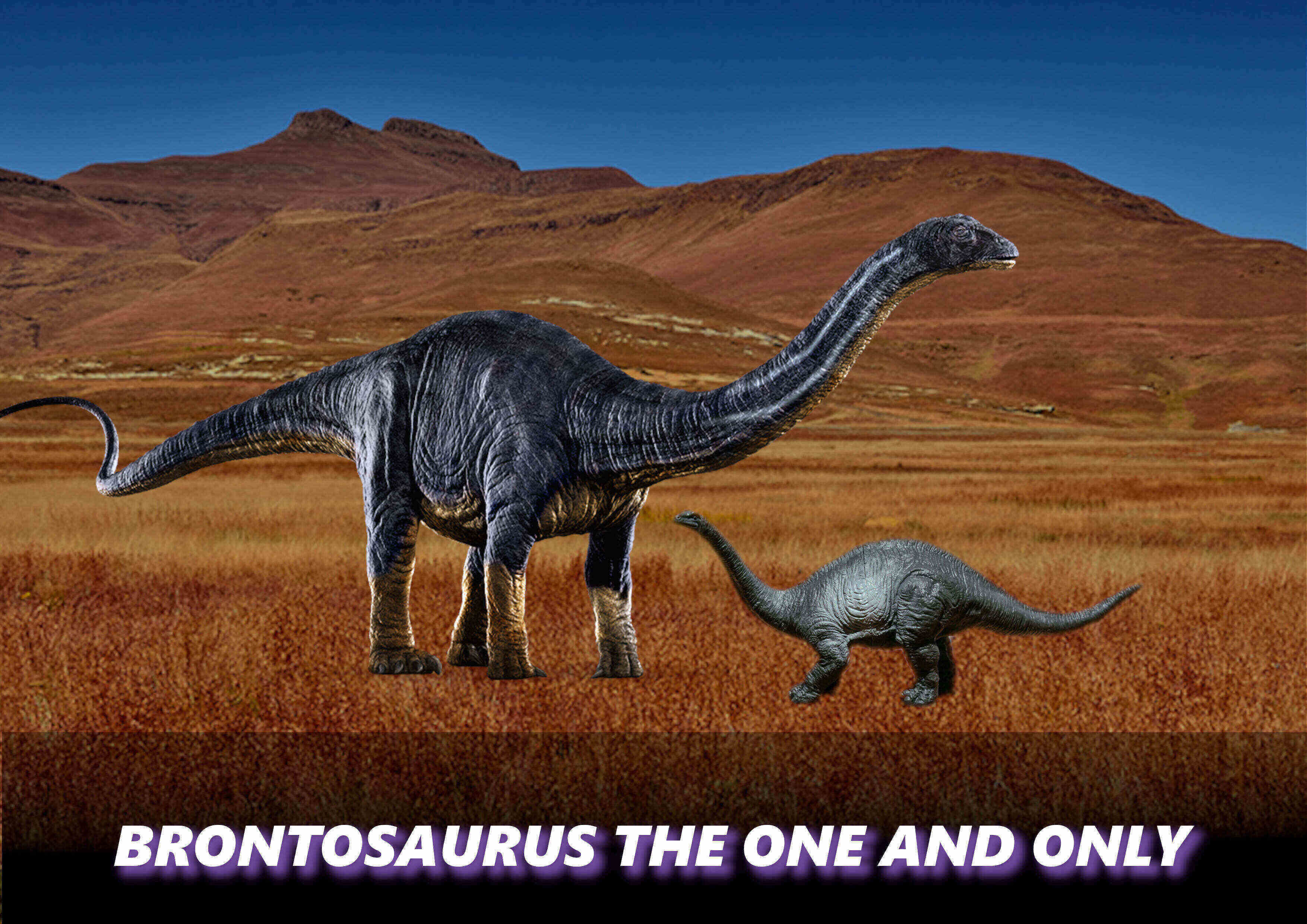
To start with GIMP a new file needs to be created. When creating, a new windows pops up asking for the pre sets of the document. My settings can be seen in the figure. For creating my own first image I took different open licensed images from the web. I dragged and dropped the images into GIMP. To change there hierarchy and visibility you can use the layer toolbar in the lower right corner. I then started to work on the background image:
- resize the image with the scale tool (press shift+s)
- create a new layer
- create a black overlay with the bucket fill tool (press shift+b)
- choose the mode linear burn
- decrease the opacity to 70 %
- add a new layer
- choose the rectangle select tool (press r)
- add a gradient (press g)
- add text (press T)
- align the layer to the image (press Q)
- Choose Filter "Drop Shadow" and choose the shadow, opacity, and color
- click on the layer with the image
- choose Fuzzy Select Tool (press U)
- make sure Antialiasing and Feather Edges are enabled
- Click on the background that you want to remove
- enable "Draw Mask" to see the selected parts for deletion
- choose the right threshold for deleting all of the background
Vector Modelling
For vector modelling I have decided to use Inkscape. I am relatively experience with this program,
but never tried parametric modelling. Inkscape has a few functions to enable parametric modelling.
The first one I tried was clone, mirror, and rotate copies.
- Go to "Objects", click on "Fill and Stroke" and remove both
- Go to "View", "Display Mode", click on "Outline"
Now, create projection lines for mirroring and cloning objects:
- Go to "Extension","Render", click on "Guides creator"
- Accept the default values (2 rows, 2 columns) and click "OK"
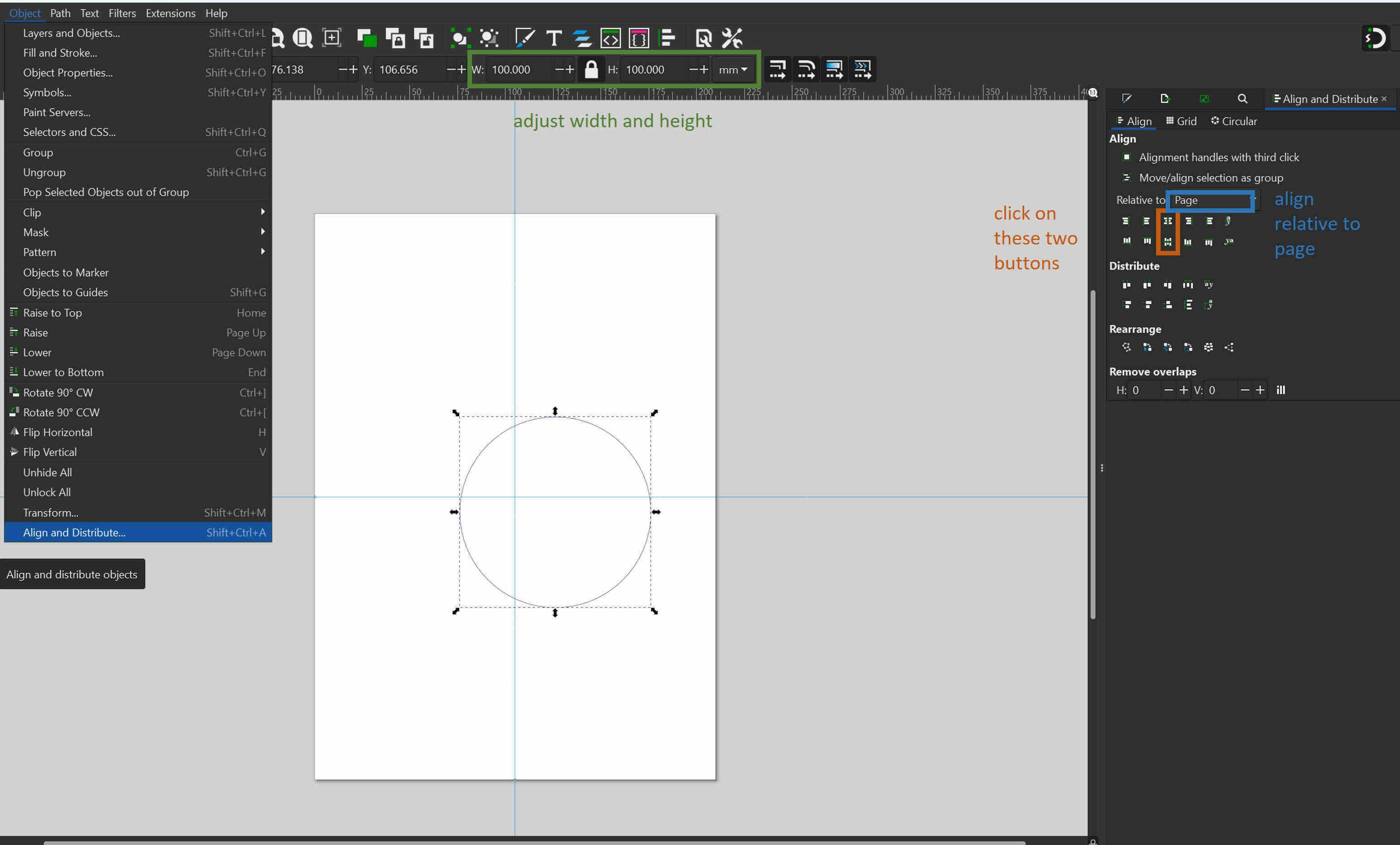
- Go to "Object","Align and Distribute"
- Align relative to page and click on the two bottons highlighted in the next image
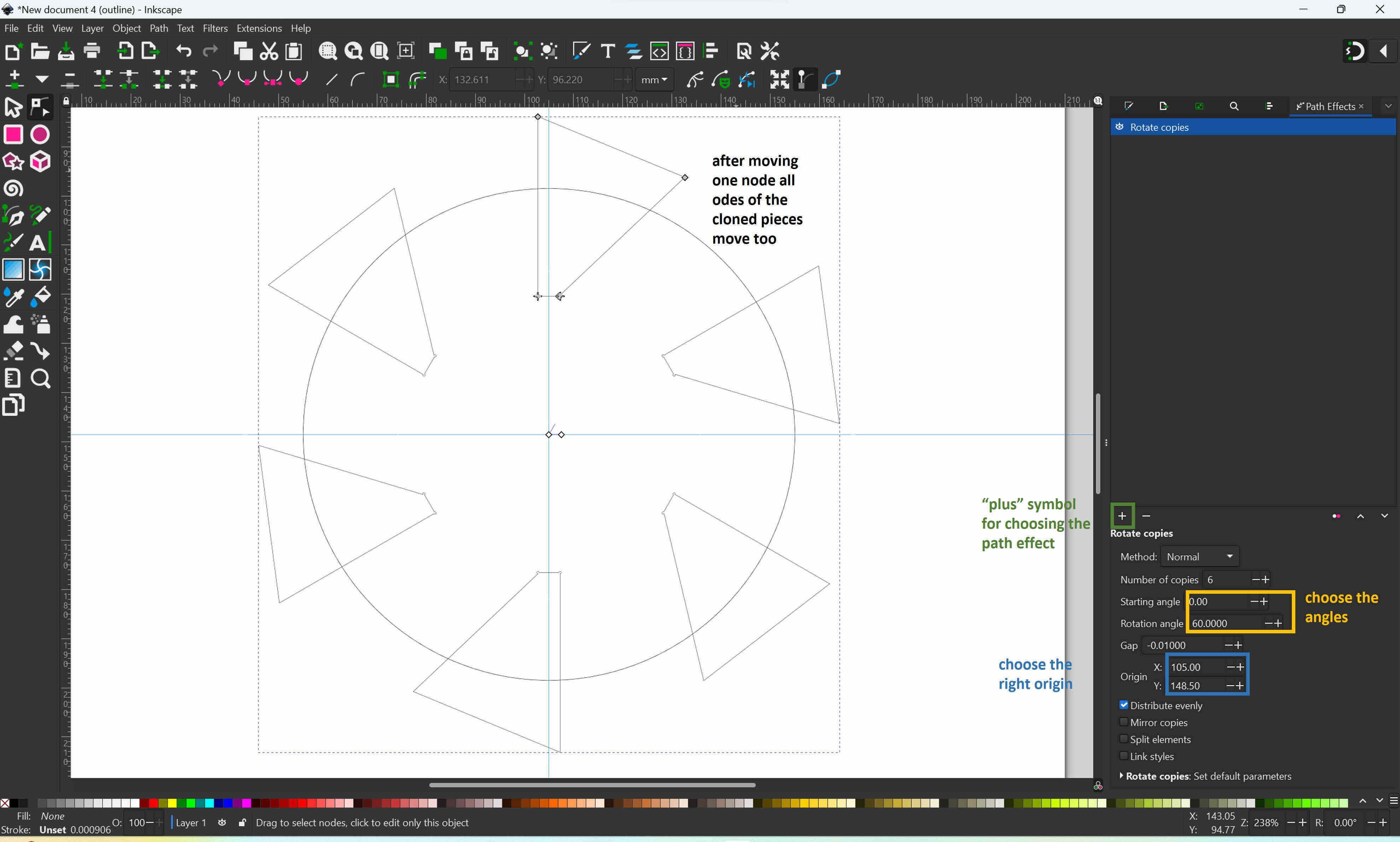
- Go to "Path", click on"Path Effects"
- Select the object you want to mirror and click on the "plus"
- Select "rotate copies"
- Choose the right "starting angle", "rotation angle" and the orgin
- Select the copies adn the circle (multiple select press shift)
- Go to "Path", click on "Difference"
Parametric Modelling in Fusion 360
For the parametric model I decided to start with a measurement tool for the correct joint connections for the laser cutter. I have already modelled this tool once for the laser cutter in the lab I am currently working and decided that this would be a good model to learn parametric modelling.
For the parametric model I decided to start with a measurement tool for the correct joint connections for the laser cutter. I have already modelled this tool once for the laser cutter in the lab I am currently working and decided that this would be a good model to learn parametric modelling.
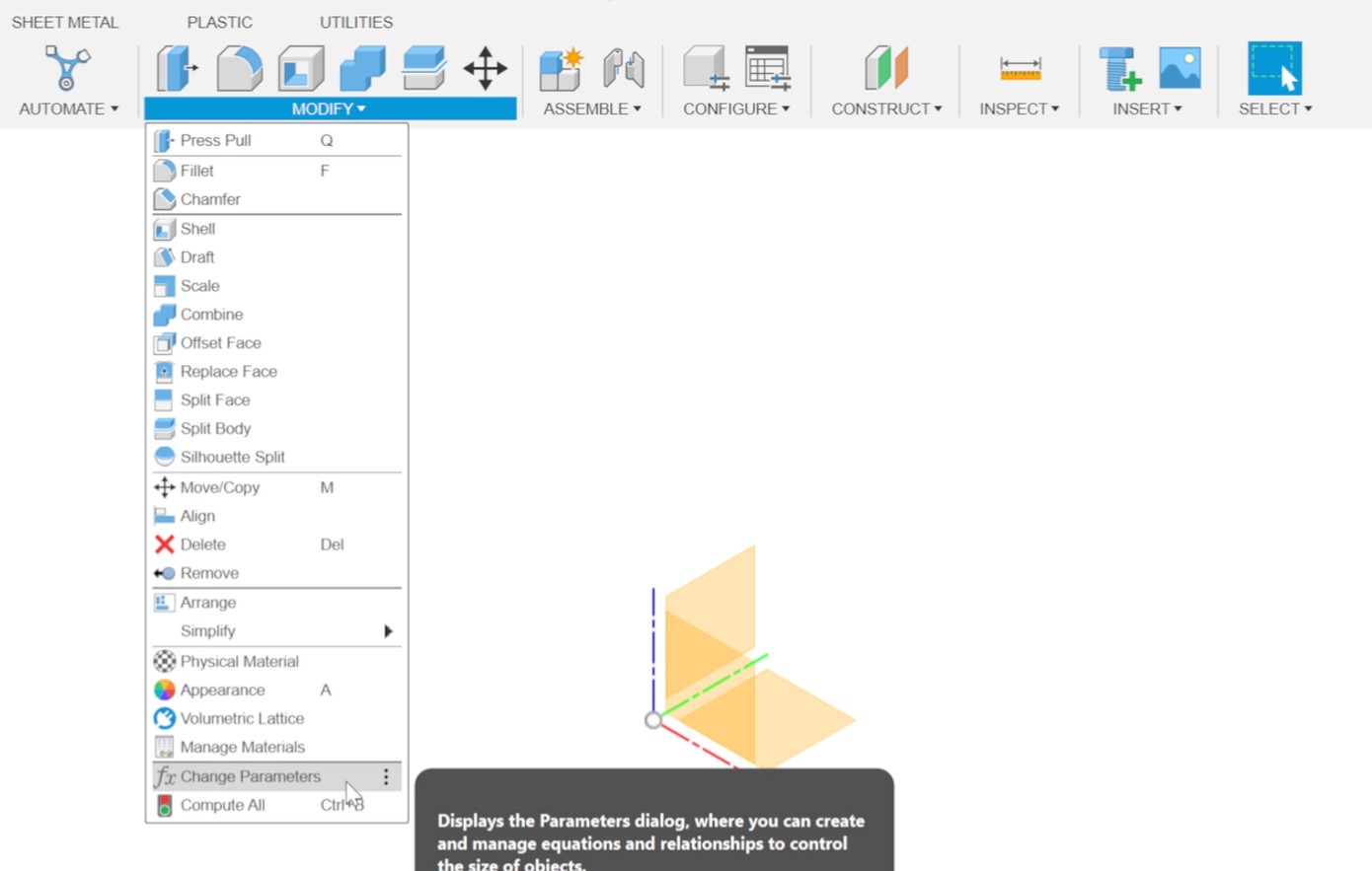
- Go to "Modify" and select "Change Parameters"
- Select "User Parameters" in the occurring windows and click on the plus symbol
- Enter your parameter
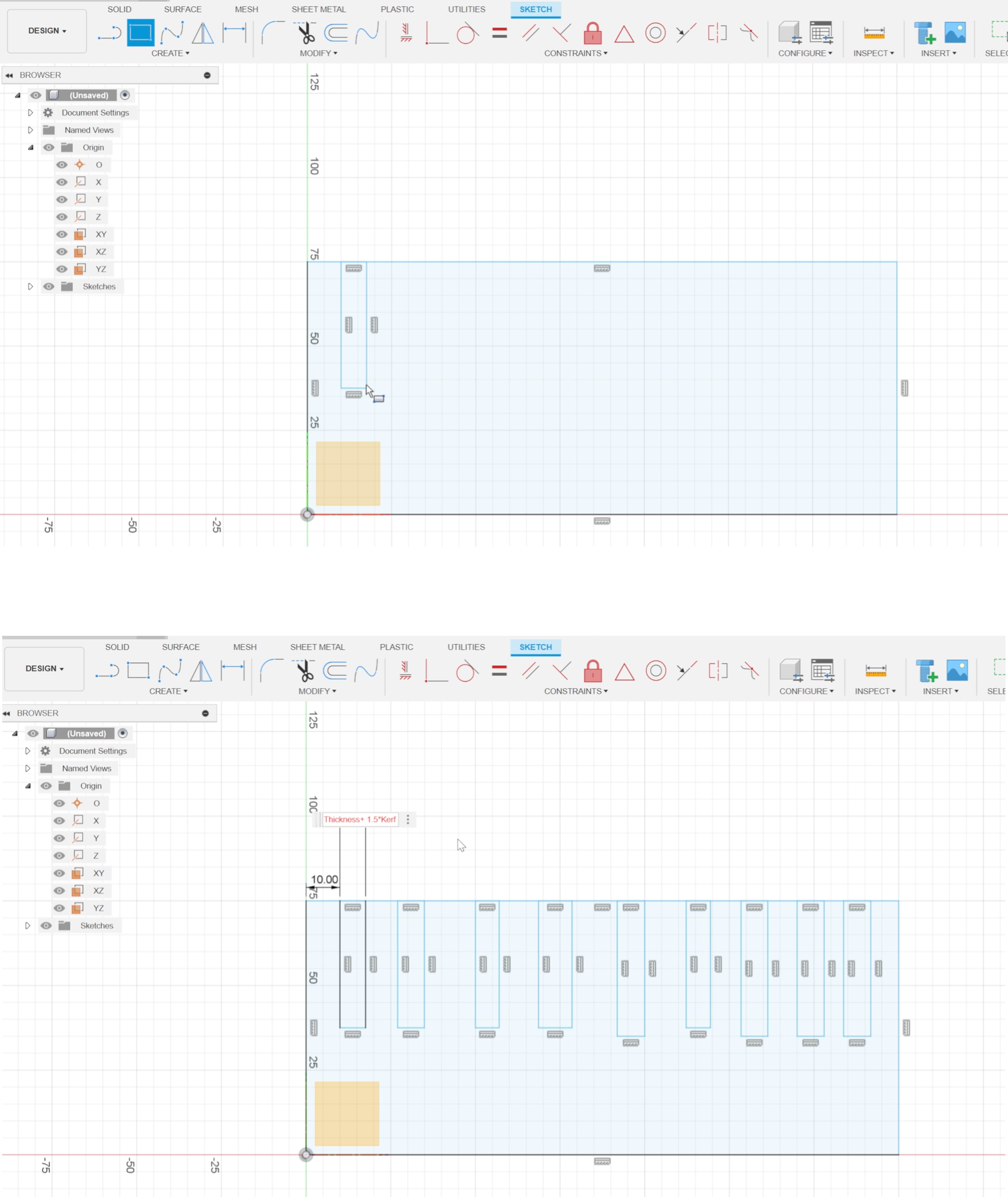
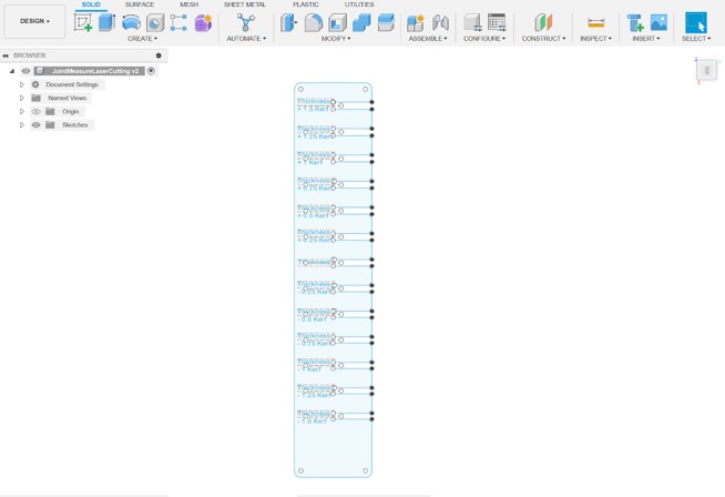
I then started a sketch in the "Design" workbench:
- Create a large rectangle with the "Rectangle" tool (press R) as the main frame
- Using the same "Rectangle" tool (R), generate 13 smaller rectangles within the large one
- Align and constrain one edge of each small rectangle to a corresponding edge of the large rectangle. Ensure precise placement for a cohesive design
- Add measurement (press D) and utilize user-defined parameters to set the width of each small rectangle as needed
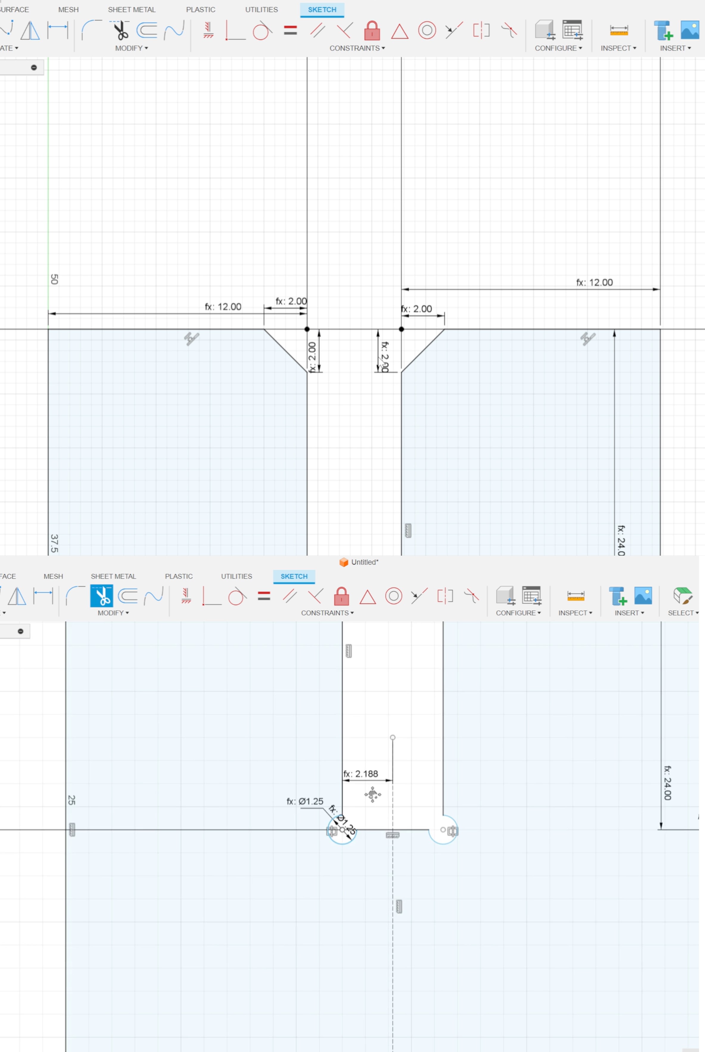
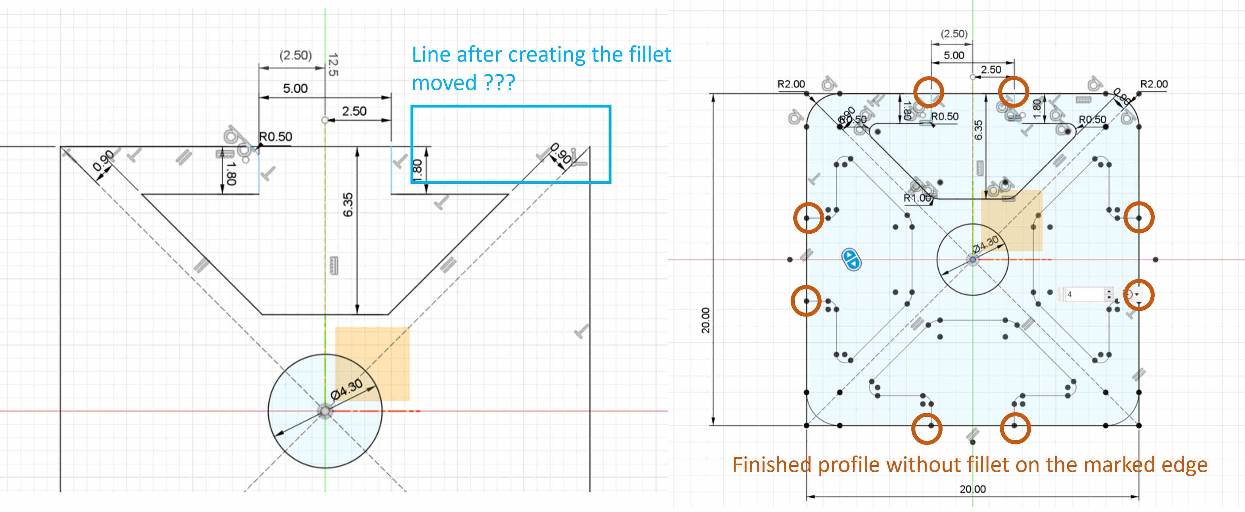
To enhance stress distribution and ensure precise assembly, I strategically incorporated chamfers and dog-bone radii in the design. The aim is to minimize stress concentration and facilitate a seamless fit between components. Chamfers serve a dual purpose by reducing stress concentration at the edges and aiding in the ease of assembly. The dog-bone radii for the inner corners ensure that connections are precise, minimizing any potential interference during assembly.
For the chamfers I used the "chamfer tool":
- Trim the line between the joint from the rectangle
- Go to modify and select "Chamfer"
- For the measurement use 0.5 * Thickness
- Create a circle
- For the measurement of the diameter use 0.5 * Thickness
- Trim the quarter of the circle
- Create a construction line (press x and create a line) in the center between the notch
- Mirror the circle
A last step it was important to include a description to of every notch:
- Got to "Create" nd click on "Text"
- Choose the position of the test and adjust the fon and font size in the occurred window on the right
3D Modelling
Inkscape to Fusion 360
In general, my current skills in Fusion 360 and oth CAD are pretty basic, but I really want to enhance them.
I inserted my Inkscape .svg file in Fusion 360
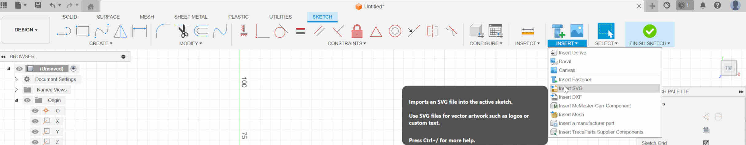
- Open a new sketch in Fusion 360 and insert the .svg file exported from Inkscape.
- Upon insertion, you may notice a change in the model's size. Resize the sketch by a factor of 3.78 to ensure accurate dimensions.
Thereafter I finished the sketch and duplicate the extruded sketch:
- Copy it eight times by left click "Copy/Move" on the body or press M
- Transform the individual bodies into components left click "Create Component" or "Assemble" click on "New Component"
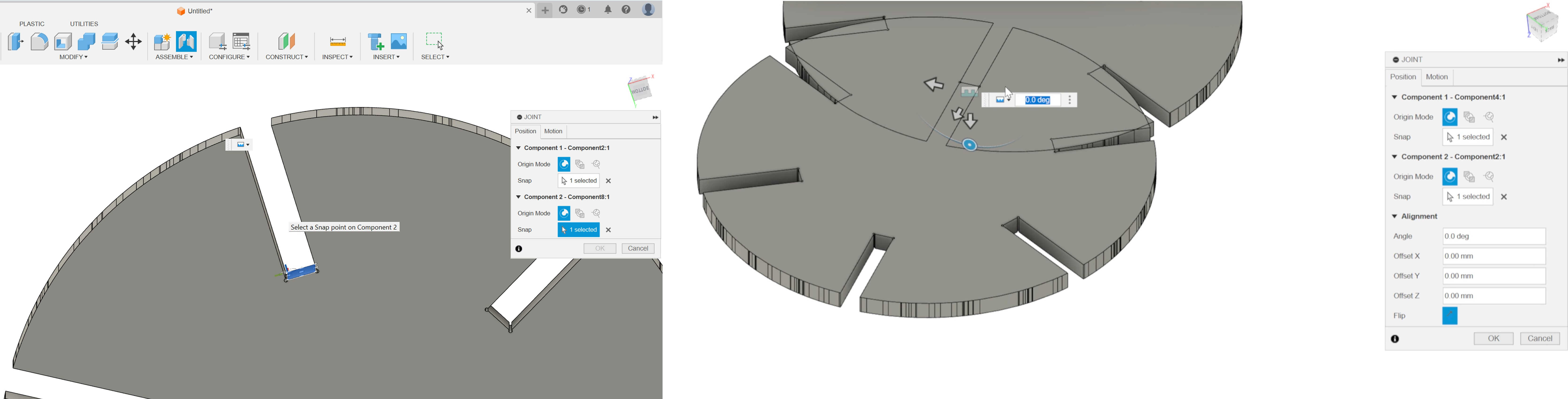
- Click on "Assemble", "Joint" to initiate the joint command (press J)
- Click on the faces inside the rectangles to connect the components
- Fine-tune the angles to prevent components from intersecting with each other
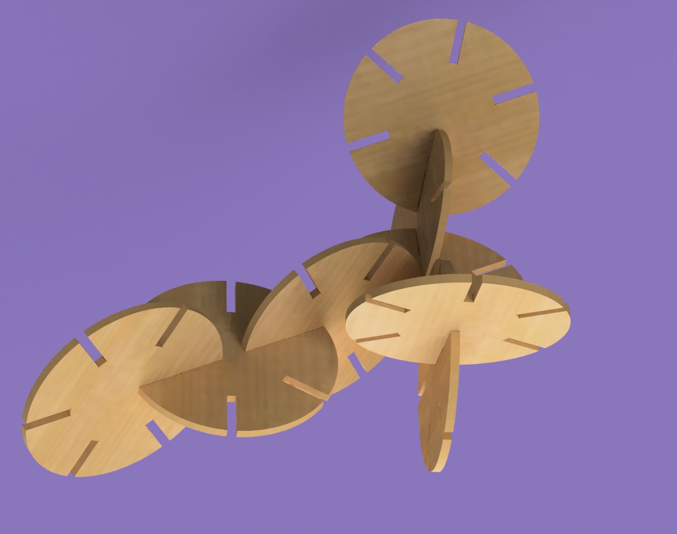
Rendering
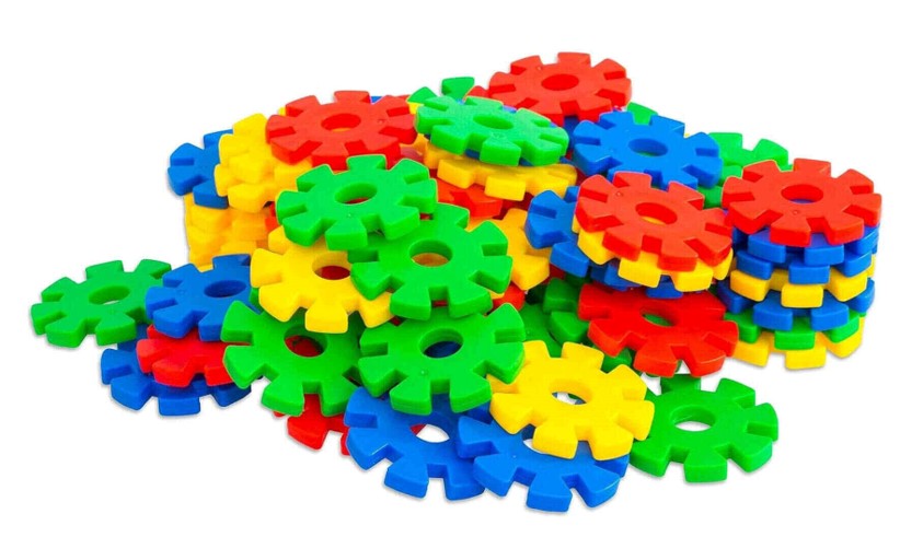
I first rendered the model of the modular kids toy parts.
- Change the workbench to render
- Click on "Appearence"
- Select all components
- Choose the material you want to use
- Click on "Scene Settings"
- Change the background and camera settings as you wish
Application on the Final Project
Modelling the Final Project
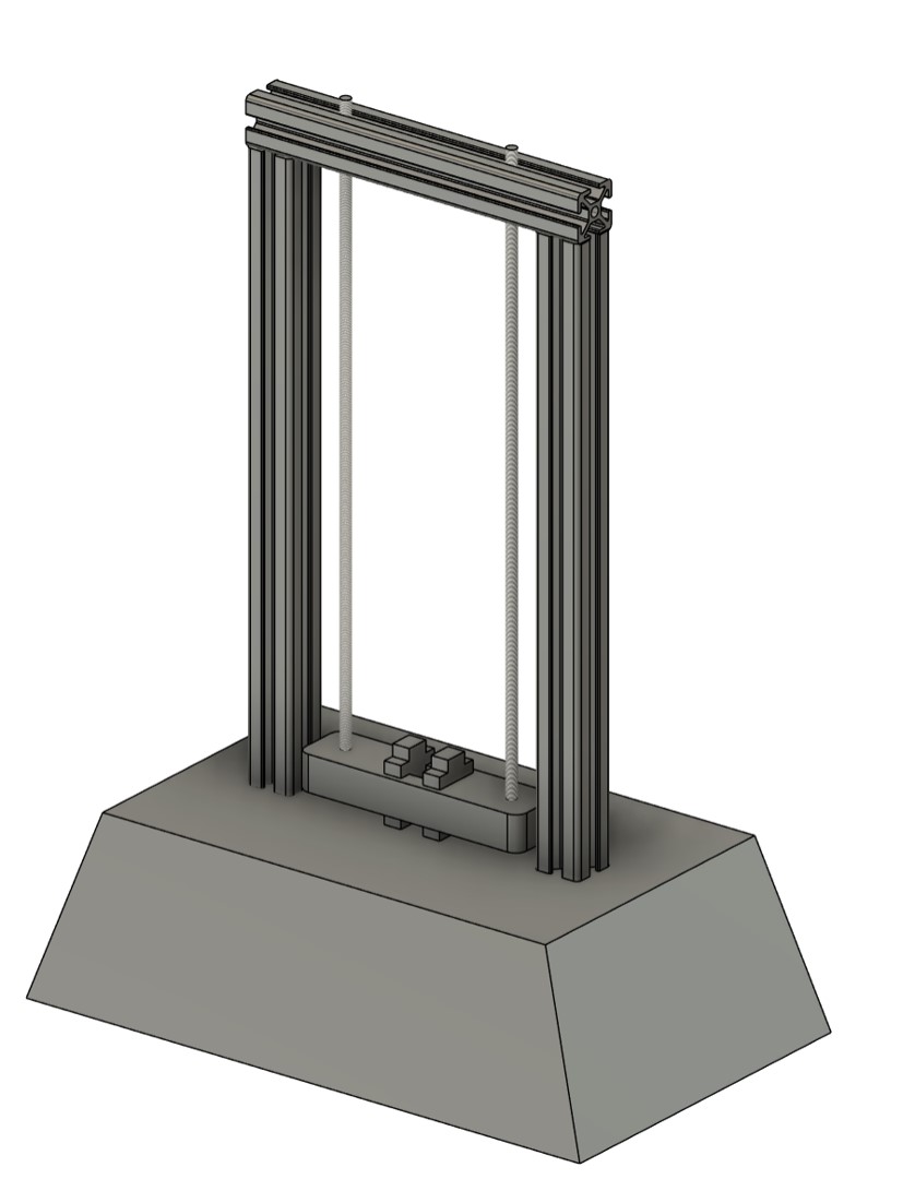
For the final project "Material Tester for Artificial Muscles" i decided to model the frame and the mounting system. The important parts are:
- The frame should be aluminum or steel
- The frame should be a modular design
- A wide base should with leveling feet should ensure secure standing
- The mounting system should be adjustable for different lengths of AMs
- The mounting system should be adjustable for different diameters or materials of AMs
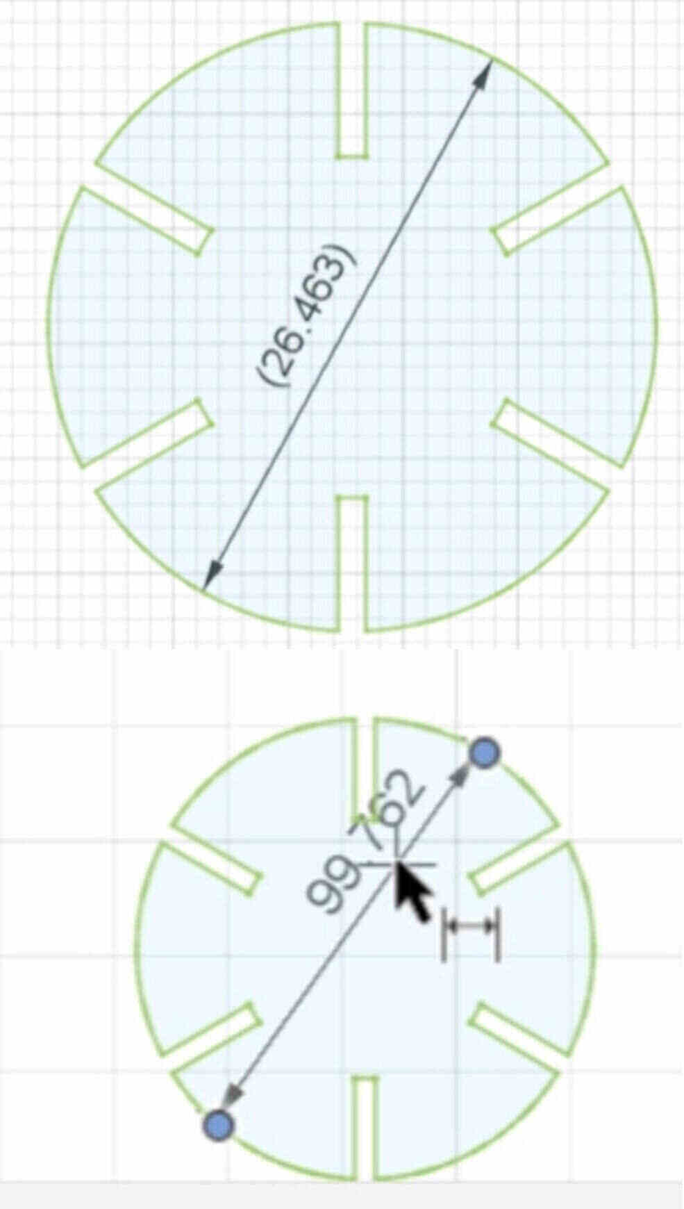
- Use the rectangle tool (center rectangle) and give measurement to the edges 7
- Use the circle tool and give measurement to the diameter
- Use the line tool and create the trapes shape on one the edges of the rectangle and apply the measurements
- Use the metal sheet fillet to create round edges
- Use the circular pattern function to clone the trapes and the fillets to the other edges of the rectangle
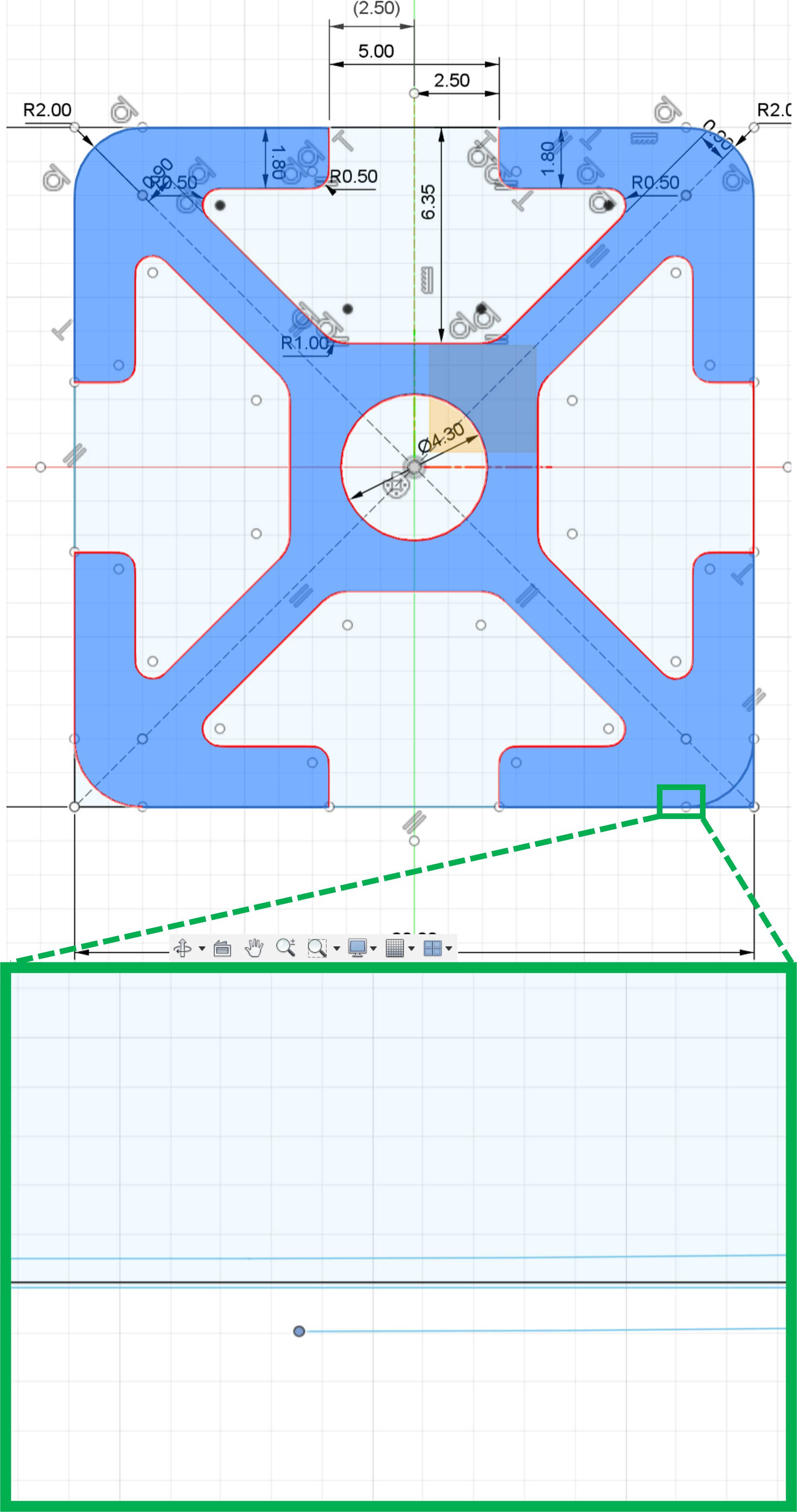
The next step for the basic frame was to extrude the profiles. For attaching the bar to the two poles, I created screw holes. To create the right holes:
- construct offset plane on the surface you want to drill holes in 7
- project important point from the surface to constrain your holes correctly
- create the holes and constrains
- use extrude for making the holes
The next component I created as the base, were the electronics, the load cell are positioned and a screen is embedded.
To create the basic shape of the base:
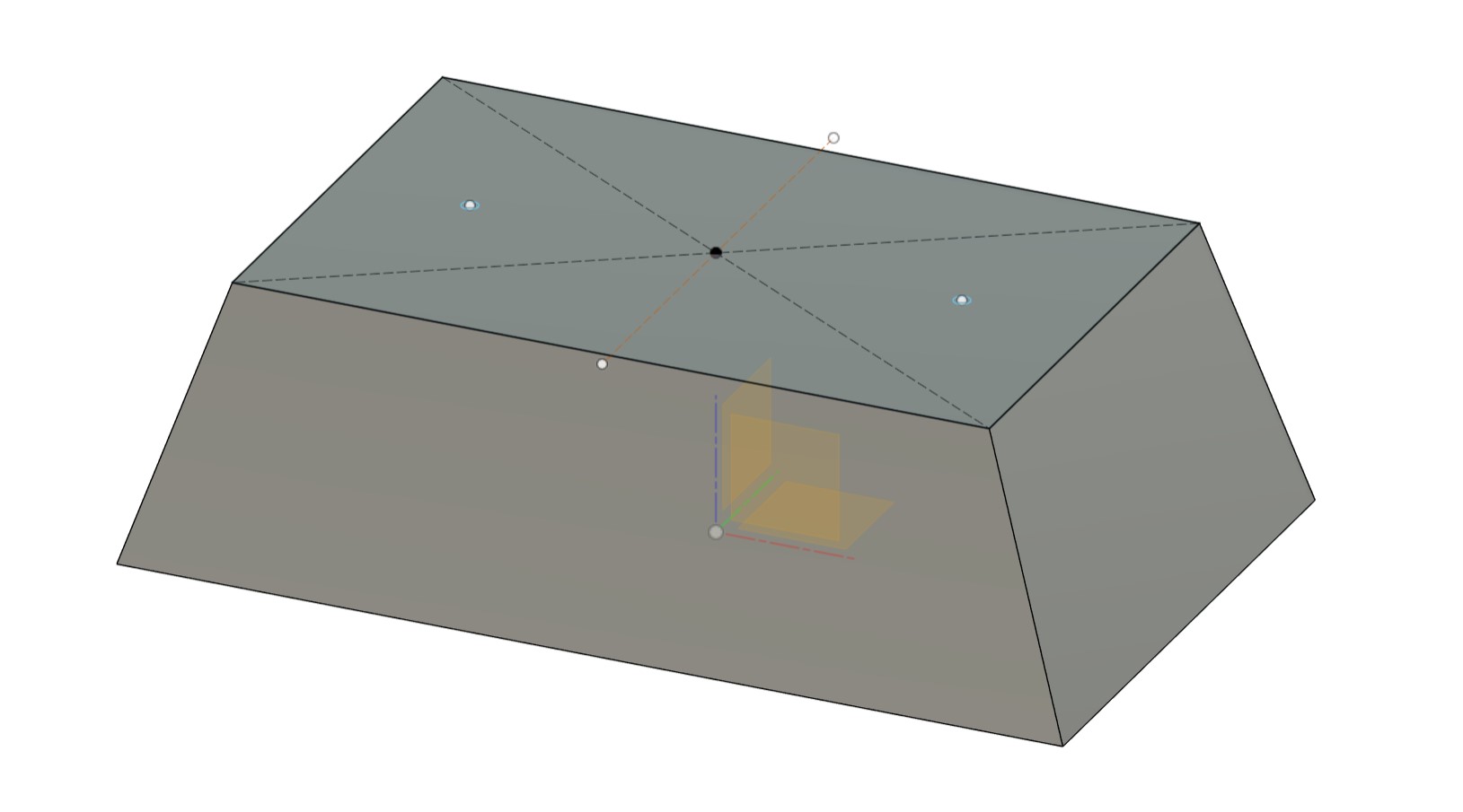
- Create a rectangle on one plane
- Construct a offset plane to the plane with the rectangle and sketch another rectangle
- create to construction circles on the rectangle, where the frame will be connected to the base
- Use the "Loft" tool and select the two rectangles
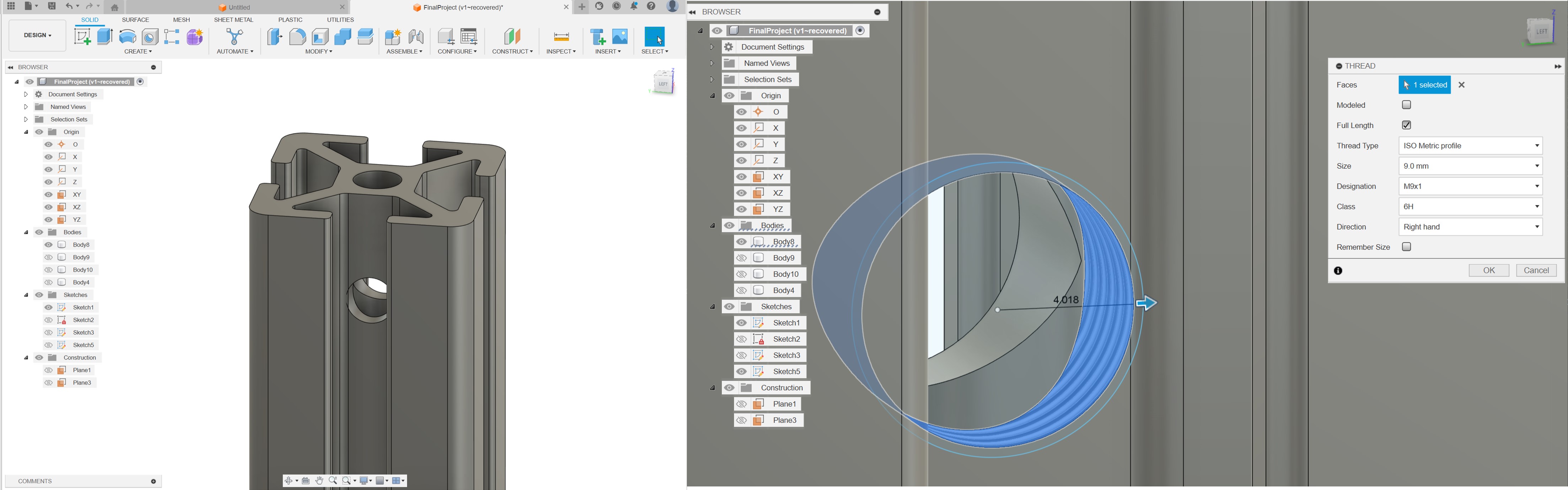
- Sketch two circle with 9 mm diameter on the offset plane of the base
- Extrude them 550 mm
- Create a thread on them (M9x1)
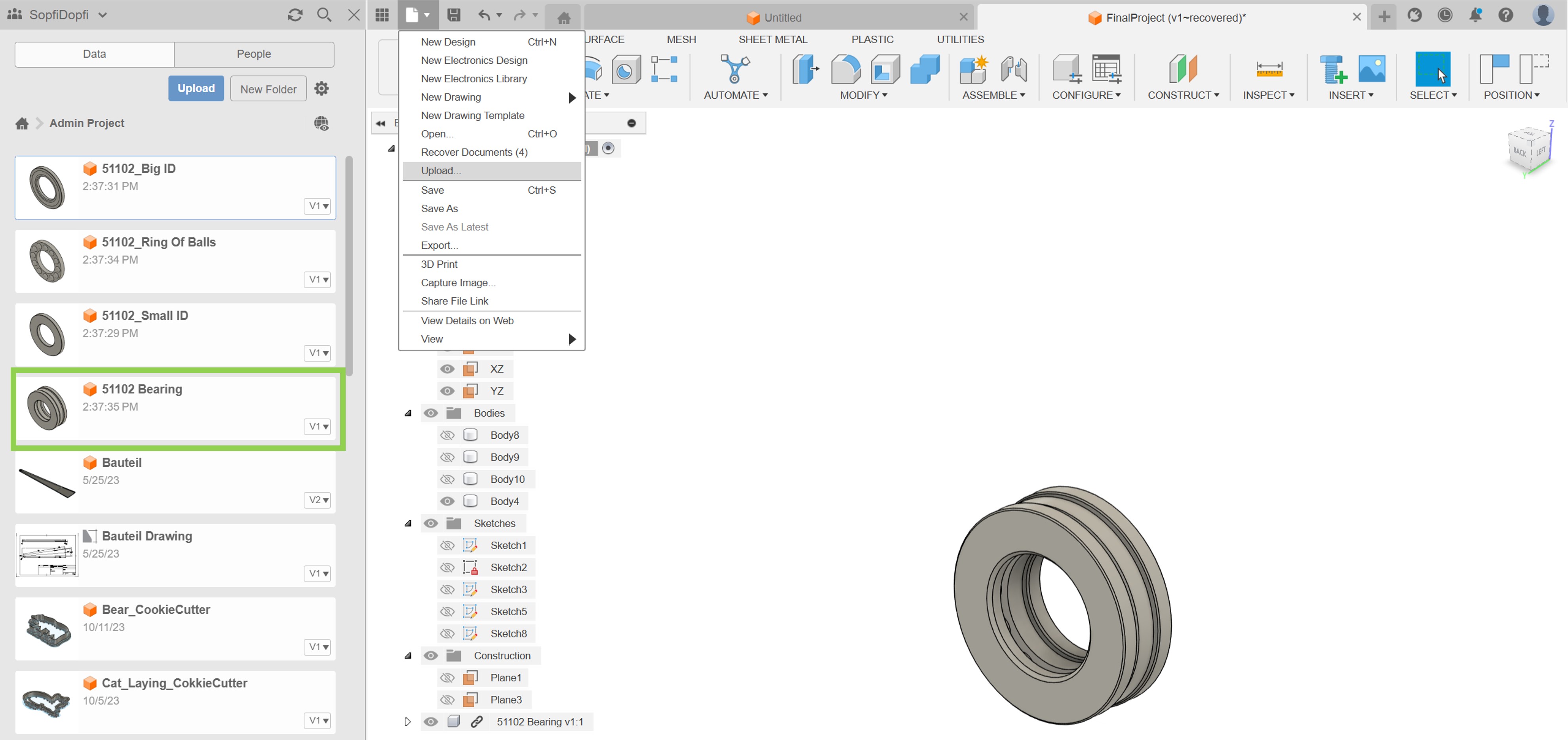
- Find the right bearings online and download a CAD-file (see here) (know these are not the right one for the forces I am using, but thea are good enough for the first model)
- Import the .stp-file by going to "File" and click on "Upload" and search for the file on your computer
- The model will appear on the right side with your project, drag and drop the model into your current project
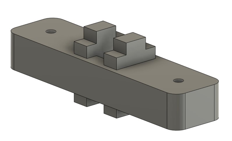
I started to create components and assemble the components:
- Go to "Assemble" and click "New Component" then click on the body you want to create a component of
- Go to "Assemble" and click on "Joint" to join the components together
- In the "Join" window decide for the type of joint (for the holding mechanism I used a "Slider")
Rendering the Final Project
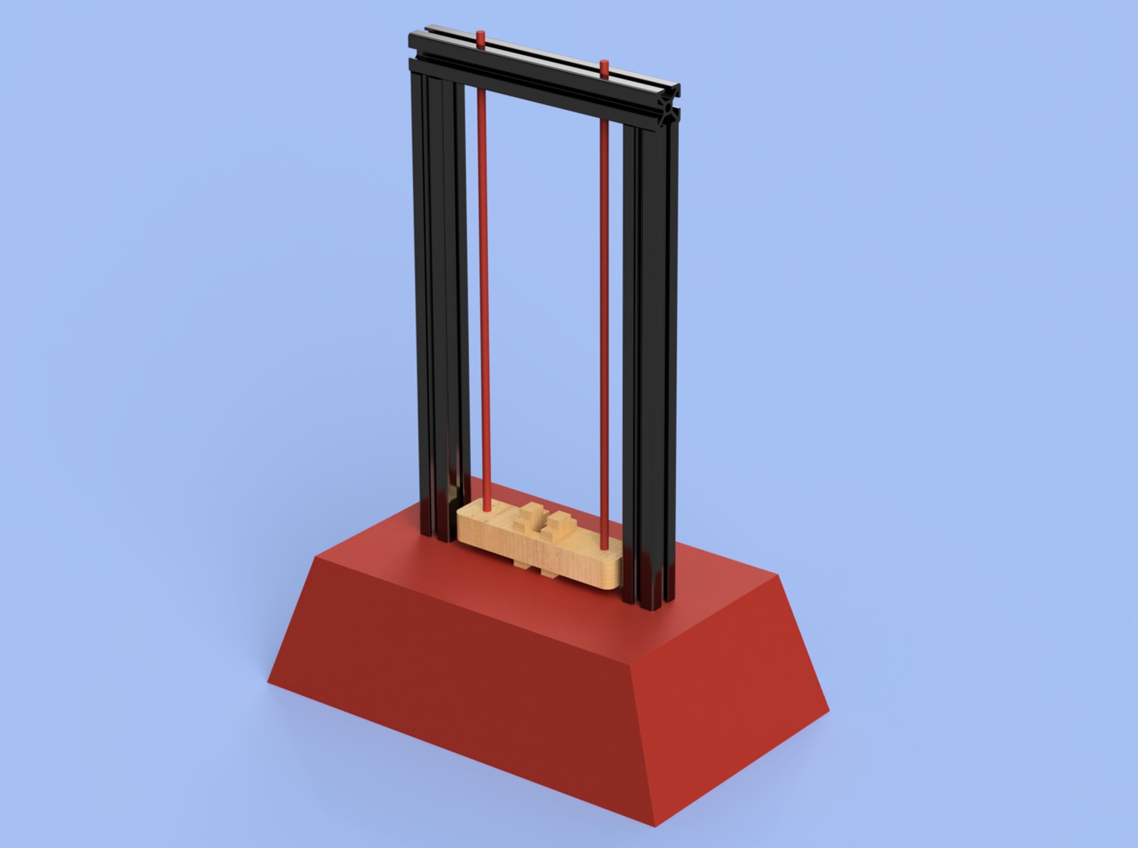
To render the project I started with changing the appearance in the workbench "Render":- Go to "Appearance" and click on the different materials you want to have in your assembly
- Drag and drop the materials on the components you want (I used aluminum for the profiles, powdered coat in red for the base, and pine wood for the clam)
- Change the settings of the scene ( I used a solid color as background, enabled mirroring on the ground, and increased the light exposure to 8.7 EV)
- Click on "Render" and enable "Local Render"
- Change The settings of the render and the final image as you prefer (I noticed a lack of quality, so I used advanced settings)
Animating the Final Project
I also wanted to try the "Animation" workbench in Fusion 360. To start with the animation, I watched a video from "The Fusion Essentials".
To create the animation:
- Go to the "Animation" workbench
- Click on "Transform Components" and select the components you want to move
- Drag the components to the position you want them to be in (or enter the numbers in the window)
- On the bottom of the Fusion 360 window there is a timeline: drag the created transformation to the right time frame and decide for a duration of your animation
- Click on the play button on the bottom of the window to see how the components would move
- Publish the video to be able to save it on your computer
Image and Video Compression
As I introduced image compression last week, I will not explain it in this chapter and rather just try to explain video compression.
- Click on effects
- Search for "Crop" in the search bar on the top of the effect panel
- Choose "Edge Crop"
- A panel on the right occurs to select the right size
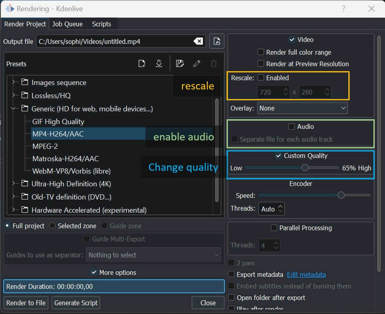
- Go to "Project" and click on "Render"
- Choose file type "MP4-H264/ACC"
- Deselect audio if you do not need it
- Rescale to your desired resolution
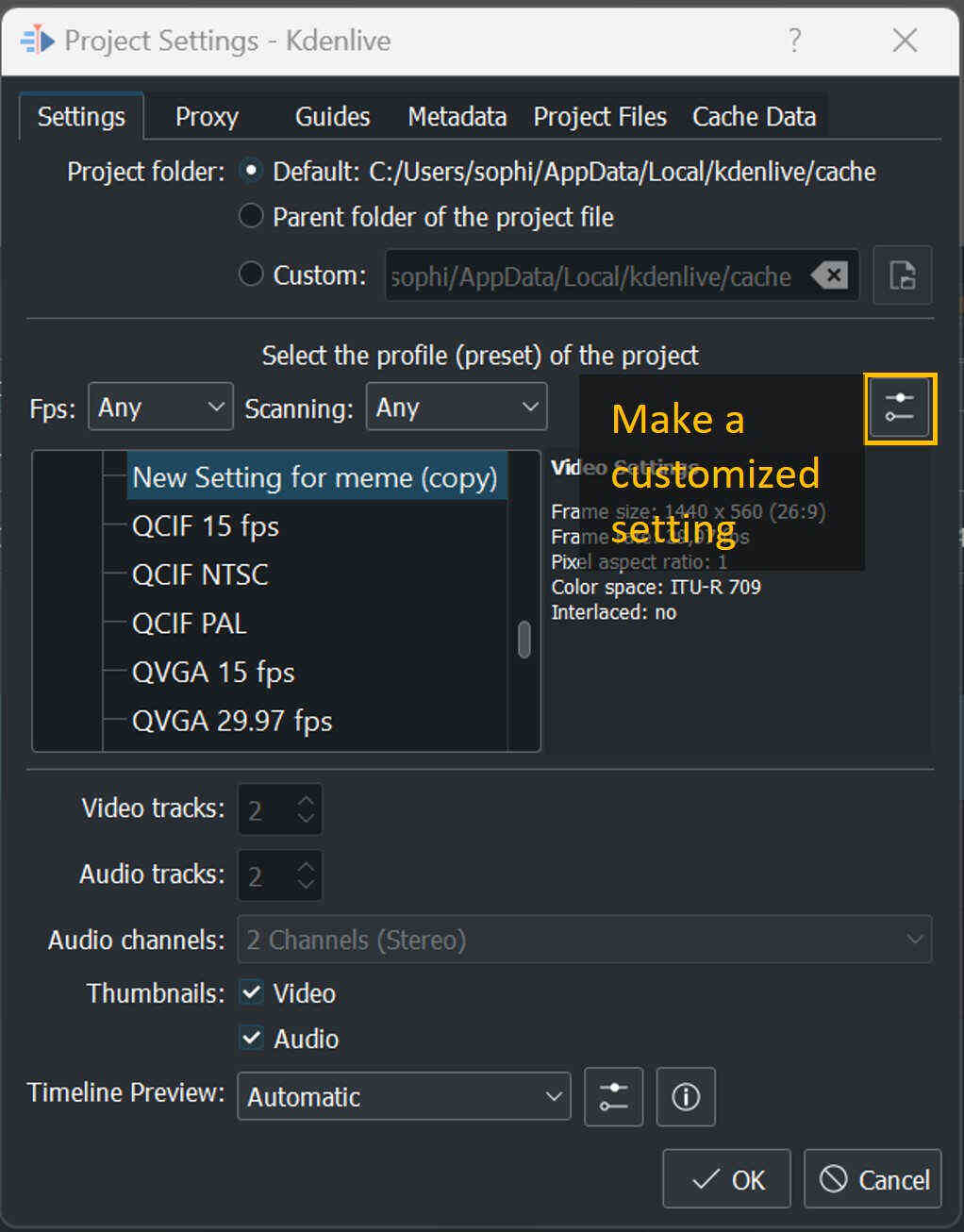
- Go to "Project" and click on "Project Settings"
- Make a customize
- Deselect audio if you do not need it
- Rescale to your desired resolution and frame rate
- Adjust the frame by clicking on "Effects" and "Position and Zoom"
Evaluation
2D Modelling
While GIMP is a versatile tool for 2D design and manipulation, it primarily focuses on raster graphics editing. Its strengths lie in tasks such as photo manipulation, digital painting, and detailed texture creation. The "Fuzzy Select" tool, along with other selection tools, facilitates the isolation and manipulation of specific regions within raster images.
For more advanced 2D modeling and vector graphics creation, Inkscape emerges as the preferred choice. Inkscape excels at producing vector graphics, offering precision and scalability crucial for intricate 2D modeling. The "Trace Bitmap" and "Simplify Path" features in Inkscape provide capabilities for converting raster images into vector graphics (which can be even more powerful when using GIMP and Inkscape together).
Inkscape's focus on vector graphics makes it ideal for creating 2D models suitable for CAD applications. The ability to produce vector graphics enables precise control over shapes and paths, crucial for technical drawings and design elements. Furthermore, Inkscape's versatility extends to various file formats, facilitating seamless integration with other applications such as laser cutting and vinyl cutting.
In summary, while GIMP serves admirably for raster graphics manipulation and basic design tasks, Inkscape stands out as the go-to tool for intricate 2D modeling and vector graphic creation compared to GIMP, offering advanced features essential for CAD applications and compatibility with various output formats.
2D to 3D
Upon uploading my Inkscape file to Fusion 360, I observed that the file was more intricate, containing numerous nodes, than necessary. In retrospect, starting my 2D model of the toy pieces directly in Fusion 360 would have yielded a faster workflow. Fusion 360's parametric modeling capabilities are notably more robust, allowing for swift adjustments to accommodate varying material thickness and laser-cutting kerfs.
The strength of Fusion 360 lies in its parametric modeling, which proves particularly advantageous when dealing with different material thicknesses and intricate adjustments. The parametric approach not only streamlines the design process but also enhances flexibility in adapting to specific manufacturing constraints. Inkscape's parametric modelling as flaws, and its possibilities of constraining a model are insubstantial.
Inkscape proves valuable for handling more organic, unsymmetrical, and unconventional 2D sketches, Fusion 360 shines in scenarios requiring precision and rapid iteration. Fusion's parametric modeling features make it easier to explore design variations and adjust parameters on the fly, ensuring efficiency in the face of changing manufacturing requirements.
Fusion 360
I've encountered some challenges with Fusion 360, as reflected in a few of my comments. While it's a powerful program, I admit to being somewhat in the learning curve, and certain logical operations don't always behave as initially understood. Fusion 360's capabilities are vast, and I've noticed that some functionalities, though present, may have nuances or may be better avoided.
In my attempts to use the scaling feature for my 2D sketches, I experienced Fusion 360 crashing on two occasions, suggesting that this tool might not be suitable for that specific application. It's essential to be cautious and explore alternative approaches or tools when encountering unexpected issues.
Another observation is Fusion 360's inclination towards cloud-based workflows. However, I've noticed that local processing often results in faster calculations, particularly during rendering. While working locally can speed up processes, there's a trade-off with a potential decrease in rendering quality. It seems that finding the right balance between cloud and local processing is crucial, depending on the specific task at hand.
In conclusion, Fusion 360's extensive capabilities come with a learning curve, and certain features may have limitations or quirks. It's essential to explore alternative methods, especially when faced with unexpected challenges, and to find the optimal balance between cloud and local processing based on the requirements of each task.
Files to Download