Input Devices
Assignments
- Group Assignment
- probe an input device's analog levels and digital signals
- Individual Assignment
- measure something: add a sensor to a microcontroller board that you have designed and read it
Load Cell and HX 711
I described the used load cell and HX 711 in week 08. In this chapter I will described how I connected the load cell and the HX 711.
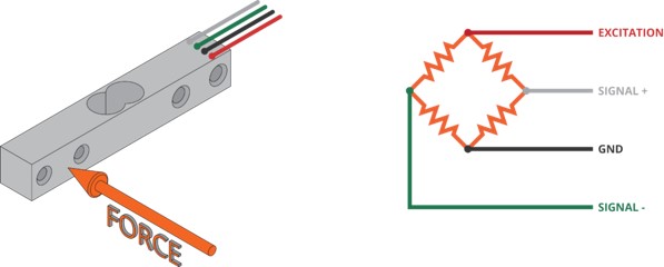
The amplifier has 6 connection for the load cell, the load cell I am using only has four cables. The question now is: How should I connect them? To find the correct connection you first have to understand the load cell. The load cell consists of four strain gauges connected via a wheat stone bridge.
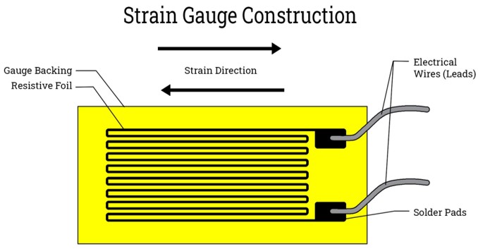
Strain gauges are thin metallic foil patterns arranged in a grid-like structure. When force is applied to the load cell, the material it's made of (often metal or semiconductor) deforms slightly. This deformation causes a change in the resistance of the strain gauge. The strain gauge is designed to be very sensitive to this change in resistance.The Wheatstone bridge is a circuit configuration commonly used to measure small changes in resistance precisely. It consists of four resistors arranged in a diamond shape, with a voltage applied across the diagonal and a voltage measured across one of the other diagonals.
In a load cell, the strain gauges are typically arranged in a Wheatstone bridge configuration. The Wheatstone bridge in a load cell consists of four resistive arms arranged in a diamond shape. Two of these arms are strain gauges, which change resistance when subjected to mechanical strain. There are usually four strain gauges in total, arranged in two pairs When weight is applied to the load cell, the strain gauges deform, causing an imbalance in the bridge. This imbalance produces a voltage difference across the bridge's output terminals, which is proportional to the applied weight. This voltage can be measured to accurately determine the weight.
To find the right connection of the 4 wires from the load cell the the HX 711, it is useful to measure resistance between the cables. The resistance between the red and the black as well as the green and the white wire should be 1 kOhm. While the resistance between for other combination should be 0.75 and 0.85 kOhm. This was correct for the load cell used. With this the correct arrangement of the cables should be:
| Wire | HX711 connection |
|---|---|
| RED | E+ |
| BLACK | E- |
| WHITE | A- |
| GREEN | A+ |
Mounting the Sensor

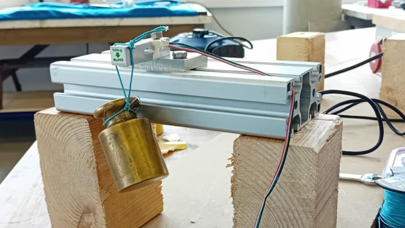
To use the sensor, it needs to be mounted to a bar strong enough to hold the force created by the artificial muscle without bending in any way. Therefore, a double aluminium profile (40 x 80 mm) was used. To mount the sensor directly to the bar a roll-in t-nut can be used, as it opted for easily sliding the sensor ot any mounted part in the furrow of the profile and reposition it, while constraining any movement when tightened. Unfortunately, when mounting the sensor directly the strain gauges would be in contact with the aluminium profile, which should be avoided as thia can lead to an error in the measurements.
Therefore, I small aluminum plate was used to be mounted between the sensor and the profile. To connect the sensor to the aluminum palte and the plate to the profile, I used a metal milling machine.
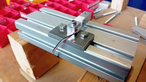
The mounting of the sensor to the profile

Correct position of the sensor between two pillars.
Testing of the Sensor
Before connecting the sensor to the board for the final project built in week 08, the correct input and measurement of the sensor was tested. Therefore, an Arduino Uno was used to connect to the HX 711.
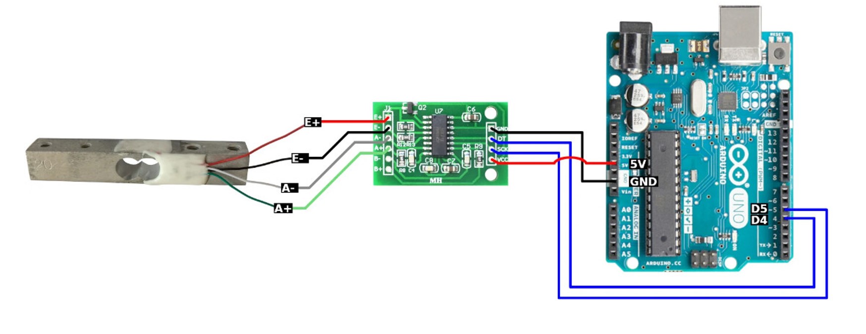
It is important to use a PWm pin for the SCK connection (here pin 5).
To test if the sensor is connected ccorrectly, I used this code at first.
	#include "HX711.h"

	// Define the pins for HX711
	const int HX711_DOUT_PIN = 4;
	const int HX711_SCK_PIN = 5;

	// Create an instance of the HX711 class
	HX711 scale;

	void setup() {
	  // Initialize serial communication
	  Serial.begin(57600);

	  // Initialize the HX711
	  scale.begin(HX711_DOUT_PIN, HX711_SCK_PIN);

	  // Set the scale to default gain of 128
	  scale.set_gain(128);
	}

	void loop() {
	  // Read the raw value from the load cell
	  long rawValue = scale.read();

	  // Print the raw value to the serial monitor
	  Serial.print(" Load cell output value: ");
	  Serial.println(rawValue);

	  // Add a delay for stability
	  delay(1000);
	}
This code created this output:
Calibrating the Load Cell
This output showed a correct connection of the load cell to the HX711 and the HX711 to the Arduino Uno. To be able to calibrate the load cell, I used the calibration library from olkal, which includes an example code to do the calibration.
To download the library and install it follow these steps.
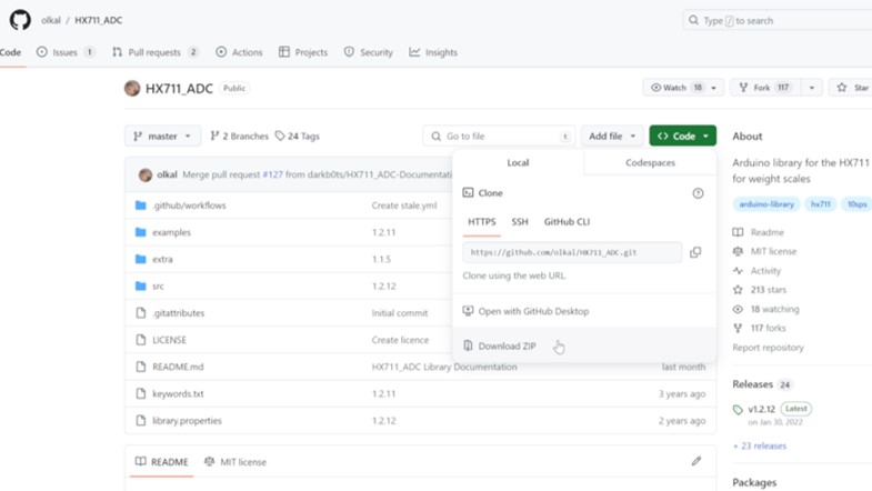
Download the .zip file of the github project.
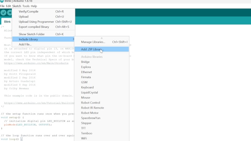
Go to "Sketch", "Include Library", and click on "Add zip library" and include the downloaded .zip file.
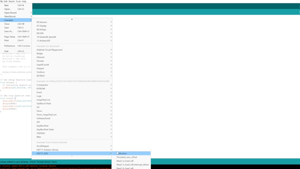
Go to "File", "Examples", and click on the "Calibration" example.
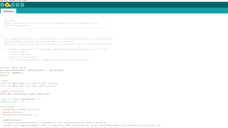
Change the pins for Dout and SCK to the correct ones of your board and upload the code to your board.
#include
#if defined(ESP8266)|| defined(ESP32) || defined(AVR)
#include
#endif

//pins:
const int HX711_dout = 4; //mcu > HX711 dout pin
const int HX711_sck = 5; //mcu > HX711 sck pin

//HX711 constructor:^
HX711_ADC LoadCell(HX711_dout, HX711_sck);

const int calVal_eepromAdress = 0;
unsigned long t = 0;

void setup() {
Serial.begin(57600); delay(10);
Serial.println();
Serial.println("Starting...");

LoadCell.begin();
//LoadCell.setReverseOutput(); //uncomment to turn a negative output value to positive
unsigned long stabilizingtime = 2000; // preciscion right after power-up can be improved by adding a few seconds of stabilizing time
boolean _tare = true; //set this to false if you don't want tare to be performed in the next step
LoadCell.start(stabilizingtime, _tare);
if (LoadCell.getTareTimeoutFlag() || LoadCell.getSignalTimeoutFlag()) {
	Serial.println("Timeout, check MCU>HX711 wiring and pin designations");
	while (1);
}
else {
	LoadCell.setCalFactor(1.0); // user set calibration value (float), initial value 1.0 may be used for this sketch
	Serial.println("Startup is complete");
}
while (!LoadCell.update());
calibrate(); //start calibration procedure
}

void loop() {
static boolean newDataReady = 0;
const int serialPrintInterval = 0; //increase value to slow down serial print activity

// check for new data/start next conversion:
if (LoadCell.update()) newDataReady = true;

// get smoothed value from the dataset:
if (newDataReady) {
	if (millis() > t + serialPrintInterval) {
	float i = LoadCell.getData();
	Serial.print("Load_cell output val: ");
	Serial.println(i);
	newDataReady = 0;
	t = millis();
	}
}

// receive command from serial terminal
if (Serial.available() > 0) {
	char inByte = Serial.read();
	if (inByte == 't') LoadCell.tareNoDelay(); //tare
	else if (inByte == 'r') calibrate(); //calibrate
	else if (inByte == 'c') changeSavedCalFactor(); //edit calibration value manually
}

// check if last tare operation is complete
if (LoadCell.getTareStatus() == true) {
	Serial.println("Tare complete");
}

}

void calibrate() {
Serial.println("***");
Serial.println("Start calibration:");
Serial.println("Place the load cell an a level stable surface.");
Serial.println("Remove any load applied to the load cell.");
Serial.println("Send 't' from serial monitor to set the tare offset.");

boolean _resume = false;
while (_resume == false) {
	LoadCell.update();
	if (Serial.available() > 0) {
	if (Serial.available() > 0) {
		char inByte = Serial.read();
		if (inByte == 't') LoadCell.tareNoDelay();
	}
	}
	if (LoadCell.getTareStatus() == true) {
	Serial.println("Tare complete");
	_resume = true;
	}
}

Serial.println("Now, place your known mass on the loadcell.");
Serial.println("Then send the weight of this mass (i.e. 100.0) from serial monitor.");

float known_mass = 0;
_resume = false;
while (_resume == false) {
	LoadCell.update();
	if (Serial.available() > 0) {
	known_mass = Serial.parseFloat();
	if (known_mass != 0) {
		Serial.print("Known mass is: ");
		Serial.println(known_mass);
		_resume = true;
	}
	}
}

LoadCell.refreshDataSet(); //refresh the dataset to be sure that the known mass is measured correct
float newCalibrationValue = LoadCell.getNewCalibration(known_mass); //get the new calibration value

Serial.print("New calibration value has been set to: ");
Serial.print(newCalibrationValue);
Serial.println(", use this as calibration value (calFactor) in your project sketch.");
Serial.print("Save this value to EEPROM adress ");
Serial.print(calVal_eepromAdress);
Serial.println("? y/n");

_resume = false;
while (_resume == false) {
	if (Serial.available() > 0) {
	char inByte = Serial.read();
	if (inByte == 'y') {
#if defined(ESP8266)|| defined(ESP32)
		EEPROM.begin(512);
#endif
		EEPROM.put(calVal_eepromAdress, newCalibrationValue);
#if defined(ESP8266)|| defined(ESP32)
		EEPROM.commit();
#endif
		EEPROM.get(calVal_eepromAdress, newCalibrationValue);
		Serial.print("Value ");
		Serial.print(newCalibrationValue);
		Serial.print(" saved to EEPROM address: ");
		Serial.println(calVal_eepromAdress);
		_resume = true;

	}
	else if (inByte == 'n') {
		Serial.println("Value not saved to EEPROM");
		_resume = true;
	}
	}
}

Serial.println("End calibration");
Serial.println("***");
Serial.println("To re-calibrate, send 'r' from serial monitor.");
Serial.println("For manual edit of the calibration value, send 'c' from serial monitor.");
Serial.println("***");
}

void changeSavedCalFactor() {
float oldCalibrationValue = LoadCell.getCalFactor();
boolean _resume = false;
Serial.println("***");
Serial.print("Current value is: ");
Serial.println(oldCalibrationValue);
Serial.println("Now, send the new value from serial monitor, i.e. 696.0");
float newCalibrationValue;
while (_resume == false) {
	if (Serial.available() > 0) {
	newCalibrationValue = Serial.parseFloat();
	if (newCalibrationValue != 0) {
		Serial.print("New calibration value is: ");
		Serial.println(newCalibrationValue);
		LoadCell.setCalFactor(newCalibrationValue);
		_resume = true;
	}
	}
}
_resume = false;
Serial.print("Save this value to EEPROM adress ");
Serial.print(calVal_eepromAdress);
Serial.println("? y/n");
while (_resume == false) {
	if (Serial.available() > 0) {
	char inByte = Serial.read();
	if (inByte == 'y') {
#if defined(ESP8266)|| defined(ESP32)
		EEPROM.begin(512);
#endif
		EEPROM.put(calVal_eepromAdress, newCalibrationValue);
#if defined(ESP8266)|| defined(ESP32)
		EEPROM.commit();
#endif
		EEPROM.get(calVal_eepromAdress, newCalibrationValue);
		Serial.print("Value ");
		Serial.print(newCalibrationValue);
		Serial.print(" saved to EEPROM address: ");
		Serial.println(calVal_eepromAdress);
		_resume = true;
	}
	else if (inByte == 'n') {
		Serial.println("Value not saved to EEPROM");
		_resume = true;
	}
	}
}
Serial.println("End change calibration value");
Serial.println("***");
}
After uploading the code, open the serial monitor and the right baud (here 57600).
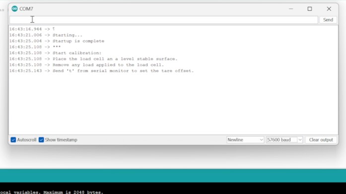
First the tare value will be set. Enter "t" into the serial monitor, while having no weight on the load cell.
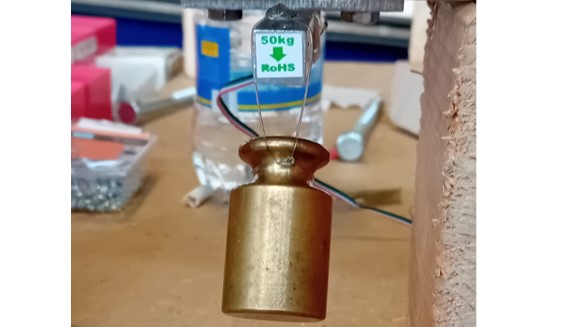
Put a weight on the load cell (here 200 g).
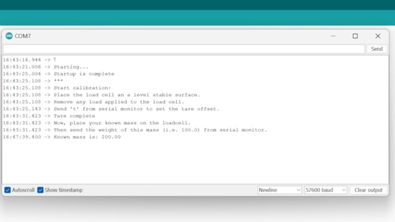
The program will ask you about the amount of mass put on the load cell. Enter the value.
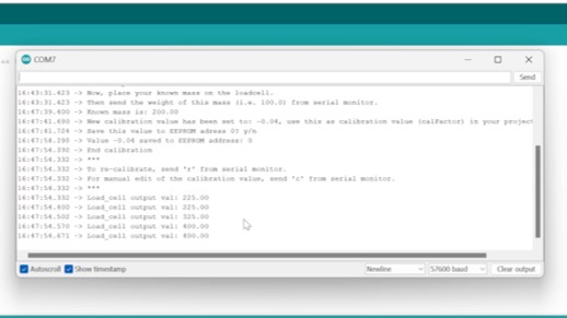
Thereafter, enter "y" to save the value.
Unfortunately, the value output made no sense. (ಠ_ಠ)
The question now: What is causing this?
Finding the origin of the wrong output of the Sensor
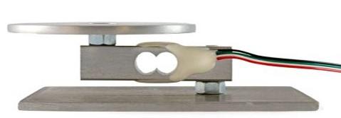
My first guess was the unusual way of mounting the load cell. In general, load cells should be mounted like shown in the picture. In the case of the application it would be beneficial to use the setup ued in the beginning. As it could be the reason for the wrong measurements, I decided to reposition the conservative load cell.
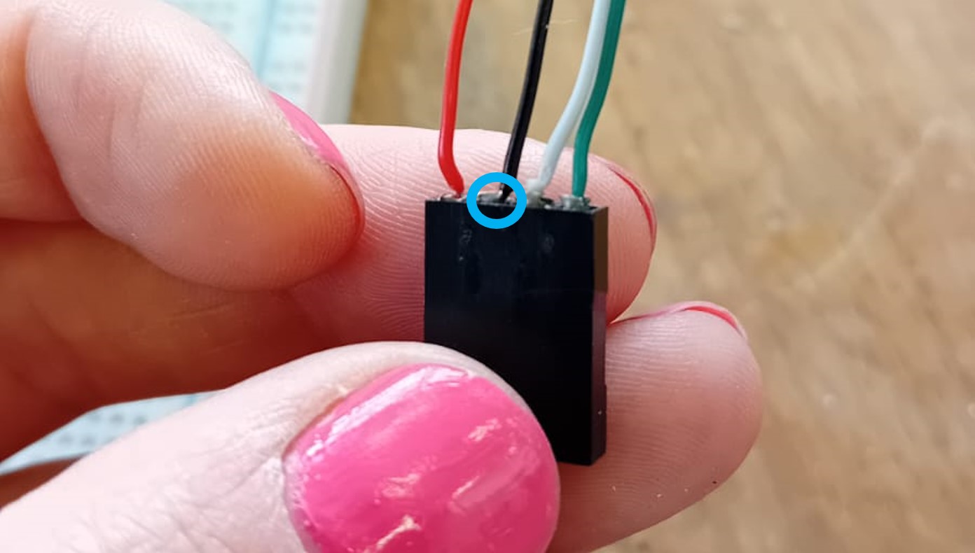
With this setup I tried to measure the values again, but the reposition had no influence on the strange error. But then i noticed something: By moving and touching the connection of the Hx711 to the load cell. Especially, when touching the female pin headers I soldered to the load cell cables.
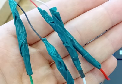
One of the cables was not soldered into the pin headers correctly and some tension lead to a loose copper wire in the cable. Therefore, I remove the pin header again. Unfortunately, there were no female pin header in the lab anymore. For a quick solution I soldered male-to-male jumper wires to the cables, and used shrinking tube and isolation tape to reduce the risk of deattachment of the coper wires to the jumper wire.
Second Test
Thereafter, the load cell was tested again with the second setup to see, if the measurements are correct. This test showed correct results for the masses put on the load cell.
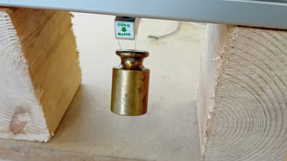
The next step, was to go back to the original setup with the load cell hanging from the profile. This setup showed correct measurements as well.
Serial Communication with my Board
After testing the code, the mounting of the load cell, and the HX 711 with an Arduino Uno, i decided to try Serial communication with my own board design and produced in week 08.
I used an FTDI break out board from Spark Fun.
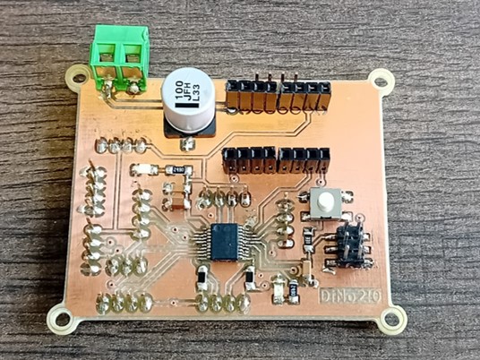
PCB of week 08
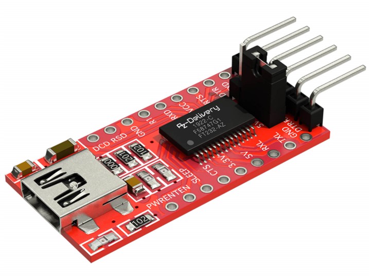
FT232-AZ USB for TTL Serial Adapter for 3.3V and 5V.
At first, I tested the communication in general. Therefore, I used a simple code, where I include the library "SoftwareSerial" with this, it is possible to use any command done with an Arduino using "Serial". Just replace "Serial" with the defined Software Serial (here "mySerial").
In this code the board just send a message to the FTDI board, which sends the message to the serial monitor. In this case, I also wanted the have a feedback about the correct upload of the code, which is indicated by the LED blinking.
#include "SoftwareSerial.h"

const int rx_pin = 6; // this is physical pin 2
const int tx_pin = 7; // this is physical pin 3

const int led_pin = 13;


SoftwareSerial mySerial(rx_pin , tx_pin);


void setup(){
  pinMode(rx_pin, INPUT);
  pinMode(tx_pin, OUTPUT);

  pinMode(led_pin, OUTPUT);


  mySerial.begin(9600); // send serial data at 9600 bits/sec
}


void loop(){

  mySerial.println("Message received"); // send the value to Serial Monitor
  digitalWrite(led_pin,HIGH);
  delay(100);
  digitalWrite(led_pin,LOW);
  delay(400);
}
After uploading the code with your programmer board, the FTDI can be connect to the USB connection. For connecting the "RX" and "TX" pins should be used. The terms "RX" and "TX" refer to "Receive" and "Transmit" respectively. They are commonly used in the context of serial communication, particularly in microcontroller and communication module setups like Arduino. When you have two devices communicating with each other, one device's RX pin (Receive pin) is connected to the other device's TX pin (Transmit pin), and vice versa. This creates a two-way communication link between the devices.
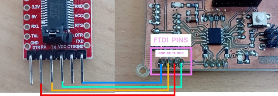
After connecting your board to the FTDI board and the FTDI board to a computer, both power LEDs should be on. If the connection is correctly, you should eb able to open the serial monitor and selct the right baud. Sometime the Port has to be changed.
Measurements with my Board
Thereafter, I uploaded a modified version of the calibration code to my board.
#include "SoftwareSerial.h"
#include "HX711_ADC.h"
#if defined(ESP8266)|| defined(ESP32) || defined(AVR)
#include "EEPROM.h"
#endif


const int rx_pin = 6; // this is physical pin 2
const int tx_pin = 7; // this is physical pin 3

const int led_pin = 13;


SoftwareSerial mySerial(rx_pin , tx_pin);

//pins:
const int HX711_dout = 2; //mcu > HX711 dout pin
const int HX711_sck = 1; //mcu > HX711 sck pin

//HX711 constructor:^
HX711_ADC LoadCell(HX711_dout, HX711_sck);

const int calVal_eepromAdress = 0;
unsigned long t = 0;

void setup() {
	pinMode(rx_pin, INPUT);
	pinMode(tx_pin, OUTPUT);

	pinMode(led_pin, OUTPUT);
	mySerial.begin(9600);
	mySerial.println();
	mySerial.println("Starting...");

	LoadCell.begin();
	//LoadCell.setReverseOutput(); //uncomment to turn a negative output value to positive
	unsigned long stabilizingtime = 2000; // preciscion right after power-up can be improved by adding a few seconds of stabilizing time
	boolean _tare = true; //set this to false if you don't want tare to be performed in the next step
	LoadCell.start(stabilizingtime, _tare);
	if (LoadCell.getTareTimeoutFlag() || LoadCell.getSignalTimeoutFlag()) {
	mySerial.println("Timeout, check MCU>HX711 wiring and pin designations");
	while (1);
	}
	else {
	LoadCell.setCalFactor(1.0); // user set calibration value (float), initial value 1.0 may be used for this sketch
	mySerial.println("Startup is complete");
	}
	while (!LoadCell.update());
	calibrate(); //start calibration procedure
}

void loop() {
	static boolean newDataReady = 0;
	const int serialPrintInterval = 0; //increase value to slow down serial print activity

	// check for new data/start next conversion:
	if (LoadCell.update()) newDataReady = true;

	// get smoothed value from the dataset:
	if (newDataReady) {
	if (millis() > t + serialPrintInterval) {
		float i = LoadCell.getData();
		mySerial.print("Load_cell output val: ");
		mySerial.println(i);
		newDataReady = 0;
		t = millis();
	}
	}

	// receive command from serial terminal
	if (mySerial.available() > 0) {
	char inByte = Serial.read();
	if (inByte == 't') LoadCell.tareNoDelay(); //tare
	else if (inByte == 'r') calibrate(); //calibrate
	else if (inByte == 'c') changeSavedCalFactor(); //edit calibration value manually
	}

	// check if last tare operation is complete
	if (LoadCell.getTareStatus() == true) {
	mySerial.println("Tare complete");
	}

}

void calibrate() {
	mySerial.println("***");
	mySerial.println("Start calibration:");
	mySerial.println("Place the load cell an a level stable surface.");
	mySerial.println("Remove any load applied to the load cell.");
	mySerial.println("Send 't' from serial monitor to set the tare offset.");

	boolean _resume = false;
	while (_resume == false) {
	LoadCell.update();
	if (mySerial.available() > 0) {
		if (mySerial.available() > 0) {
		char inByte = mySerial.read();
		if (inByte == 't') LoadCell.tareNoDelay();
		}
	}
	if (LoadCell.getTareStatus() == true) {
		mySerial.println("Tare complete");
		_resume = true;
	}
	}

	mySerial.println("Now, place your known mass on the loadcell.");
	mySerial.println("Then send the weight of this mass (i.e. 100.0) from serial monitor.");

	float known_mass = 0;
	_resume = false;
	while (_resume == false) {
	LoadCell.update();
	if (mySerial.available() > 0) {
		known_mass = mySerial.parseFloat();
		if (known_mass != 0) {
		mySerial.print("Known mass is: ");
		mySerial.println(known_mass);
		_resume = true;
		}
	}
	}

	LoadCell.refreshDataSet(); //refresh the dataset to be sure that the known mass is measured correct
	float newCalibrationValue = LoadCell.getNewCalibration(known_mass); //get the new calibration value

	mySerial.print("New calibration value has been set to: ");
	mySerial.print(newCalibrationValue);
	mySerial.println(", use this as calibration value (calFactor) in your project sketch.");
	mySerial.print("Save this value to EEPROM adress ");
	mySerial.print(calVal_eepromAdress);
	mySerial.println("? y/n");

	_resume = false;
	while (_resume == false) {
	if (mySerial.available() > 0) {
		char inByte = mySerial.read();
		if (inByte == 'y') {
#if defined(ESP8266)|| defined(ESP32)
		EEPROM.begin(512);
#endif
		EEPROM.put(calVal_eepromAdress, newCalibrationValue);
#if defined(ESP8266)|| defined(ESP32)
		EEPROM.commit();
#endif
		EEPROM.get(calVal_eepromAdress, newCalibrationValue);
		mySerial.print("Value ");
		mySerial.print(newCalibrationValue);
		mySerial.print(" saved to EEPROM address: ");
		mySerial.println(calVal_eepromAdress);
		_resume = true;

		}
		else if (inByte == 'n') {
		mySerial.println("Value not saved to EEPROM");
		_resume = true;
		}
	}
	}

	mySerial.println("End calibration");
	mySerial.println("***");
	mySerial.println("To re-calibrate, send 'r' from serial monitor.");
	mySerial.println("For manual edit of the calibration value, send 'c' from serial monitor.");
	mySerial.println("***");
}

void changeSavedCalFactor() {
	float oldCalibrationValue = LoadCell.getCalFactor();
	boolean _resume = false;
	mySerial.println("***");
	mySerial.print("Current value is: ");
	mySerial.println(oldCalibrationValue);
	mySerial.println("Now, send the new value from serial monitor, i.e. 696.0");
	float newCalibrationValue;
	while (_resume == false) {
	if (mySerial.available() > 0) {
		newCalibrationValue = mySerial.parseFloat();
		if (newCalibrationValue != 0) {
		mySerial.print("New calibration value is: ");
		mySerial.println(newCalibrationValue);
		LoadCell.setCalFactor(newCalibrationValue);
		_resume = true;
		}
	}
	}
	_resume = false;
	mySerial.print("Save this value to EEPROM adress ");
	mySerial.print(calVal_eepromAdress);
	mySerial.println("? y/n");
	while (_resume == false) {
	if (mySerial.available() > 0) {
		char inByte = mySerial.read();
		if (inByte == 'y') {
#if defined(ESP8266)|| defined(ESP32)
		EEPROM.begin(512);
#endif
		EEPROM.put(calVal_eepromAdress, newCalibrationValue);
#if defined(ESP8266)|| defined(ESP32)
		EEPROM.commit();
#endif
		EEPROM.get(calVal_eepromAdress, newCalibrationValue);
		mySerial.print("Value ");
		mySerial.print(newCalibrationValue);
		mySerial.print(" saved to EEPROM address: ");
		mySerial.println(calVal_eepromAdress);
		_resume = true;
		}
		else if (inByte == 'n') {
		mySerial.println("Value not saved to EEPROM");
		_resume = true;
		}
	}
	}
	mySerial.println("End change calibration value");
	mySerial.println("***");
}
Then I connected the board to the computer with the FTDI board.
Then I started the calibration of the board via the serial monitor.
I then tested 0 g, 200 g, and 500 g as weights to see, if the Calibration worked out.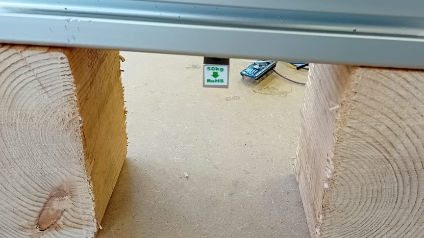
The output showed a successful calibration. Additionally, as the values show an error that is not systematic, but random as the value vary around the true value of the weight.