Week 4 - Electronics Production
This week focused on producing PCB boards using the milling machine. When I learned how to operate the milling machine, me and my fab group created this workflow.
PCB Board
For this week, we created a circuit board by Quentorres that will allow us to program chips and also has some other fun capabilities as well. The board design was given to us be our teachers and we followed the schematics while milling and soldering the board.
Milling the board
To mill the board, we used 3 different End Mill bits. We used a 1/64 bit, a 1/32 bit, and a 1/16 bit. The machine we used was an OtherMill Pro. To make setting up the machine easier in the future, our group created this Workflow.
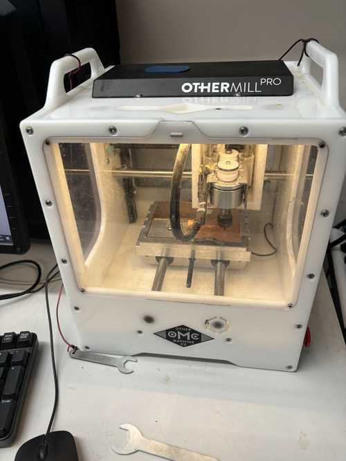
The first step in the workflow was to put the copper plate shown below onto the machine using Nitto Tape.
 4321Then we had to create the GCode using Bantam Tools.

Finally, I milled the board as shown in the video below
Final Product
After milling, I vacuumed and washed the board to get an amazing final product.

Difficulties
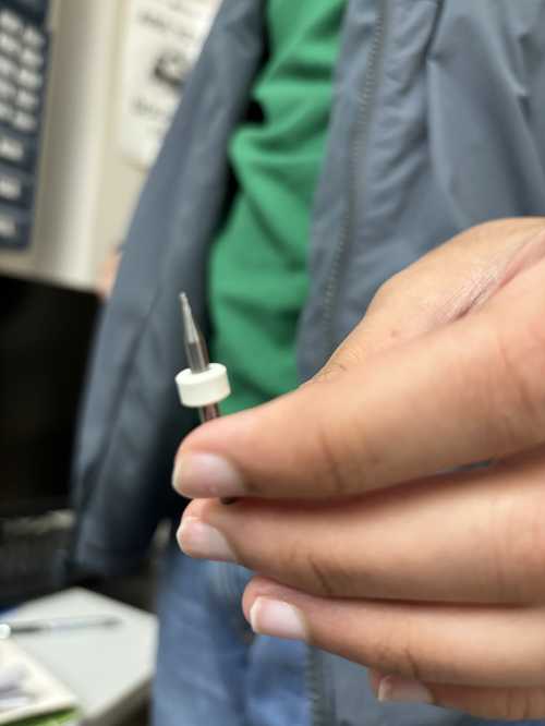
When I was milling a second PCB board, I realized something was wrong when the sound of the speed up of the spindle was happening but the bit didn't look like it was spinning. I paused the cut and called over a teacher, and it turns out that the band that connects the bit to the spindle had broken. Luckily, due to me pausing the cut before the spindle lowered, the bit was preserved.
Another problem I had while milling was that we used a 1/32 bit to do the outside cutout and ended up braking it.
As to not have this problem again, I started incorporating a 1/16 bit into the Gcode. Though this worked in the beginning, I eventually ran into a problem. The 1/16 would rip the entire copper plate off the board and we would have to stop the cut. After some investigation, we realized that the problem was the 1/16 bit would go 1 mm in for each pass which is a lot for our copper plate so it would end up grabbing the whole board and taking it with it. To fix this, we created a preset by copying the provided 1/16 bit settings and changing the depth to 0.25 mm.
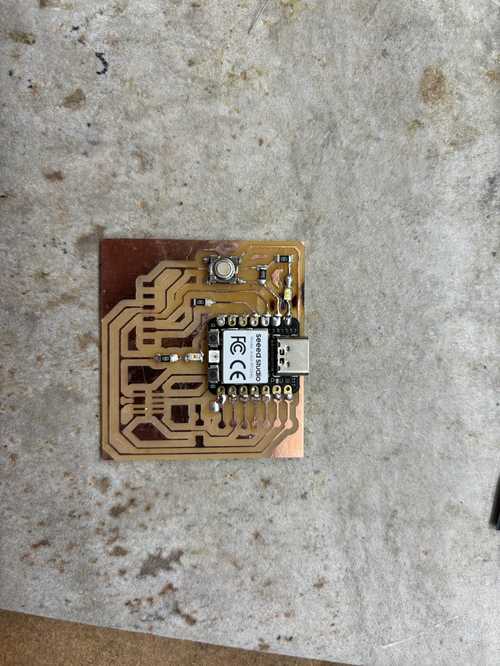
Soldering the Board
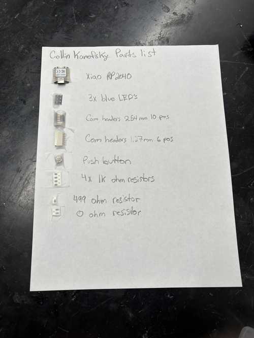
After the board finished milling, I then had to add the components onto the board. To start I layed put and labeled all the components I would need based on the schematics given.
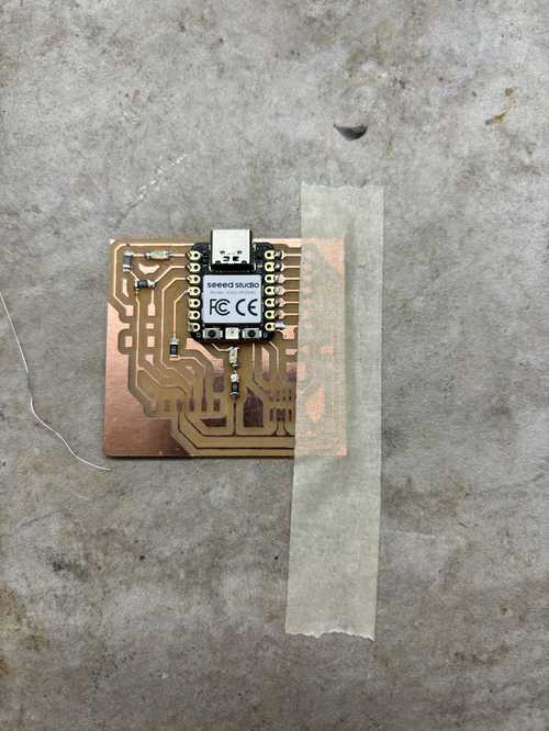
Next, I learned about solder paste and after seeing how easy and efficient it was, I decided that the best method for attaching the Seeed with all its ports would be to use the paste and a heat gun. However, later on, this would come back to hurt me.

After I soldered on the Seeed, I proceeded to solder the rest of the components based on the schematics.


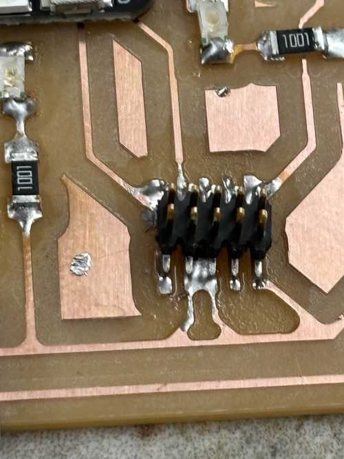
Difficulties
When I was soldering my board and testing components with a multimeter, I ran into one of my LED's which would turn on when not attached to the board, but when soldered on, wouldn't turn on. After lots of troubleshooting, I figured out that the port of the Seeed the LED was connected to had bridged with next port over. This was because when I heated the paste, I went to fast and some unmelted paste allowed for a solder bridge hidden under the seeed. To fix this issue, I used a heat gun to re melt the solder and the heat eventually reached the unmelted paste fixing the problem.
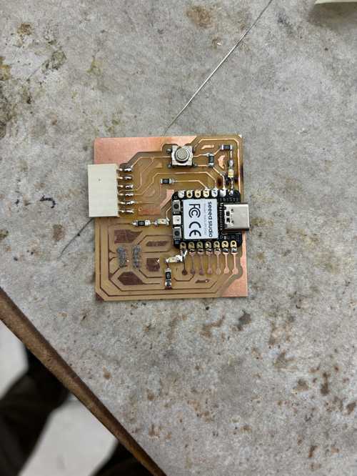
Programming the board
To even begin programming the board, I first needed to understand the different ports of the Seeed RP240 micro controller. To do so, I uses Adrian Torres's Documentation to learn what each port did. Once I was familiar with the board, I downloaded the arduino software.
To test the functionality of my board, I decided to create a simple blinking LED code. However, before I uploaded it, I needed to add the RP2040 as a board. To do this, you need to go to File > Preferences and in the Additional Boards Manager URL area, type
https://github.com/earlephilhower/arduino-pico/releases/download/global/package_rp2040_index.json
Now, if you go into the boards library, there will be an option to download a library called Raspberry Pi Pico/RP240.
After downloading, when selecting boards, search Seeed RP2040 and select it. These instructions were derived from Seeed Studios.
Below is a video of the blink code running on my board.
After testing the LEDs, I proceeded to test the button as seen in this next video
Group Assignment
This link goes to our group project
Reflection
This week was super informative and eye opening. From the milling process of a PCB board to the different methods of soldering and programming, I learned many new skills. In the group assignment, I learned the constraints and parameters of my milling machine, how thin I can create traces, and how to get a professionally created custom board delivered for your use.