7. Computer-Controlled Machining
Group assignment:
-
Complete your lab’s safety training
-
Test runout, alignment, fixturing, speeds, feeds, materials and toolpaths for your machine
-
Document your work to the group work page and reflect on your individual page what you learned
Individual project
- Make (design+mill+assemble) something big
Download Design Files
Click here to download my design files folder
Group Work Reflection
For our group project, we reviewed the safety procedures for the ShopBot PRSalpha. It was very eye-opening to learn about how dangerous such machinery truly is and how important it is to follow our lab’s safety procedures. Additionally, we also tested runout, alignment, fixturing, speeds, feeds, materials and toolpaths for our machine. It was interesting to see how each individual piece of the CNC process can have such a big impact on the finished product – there is truly no “bs-ing” with CNCing… and any attempt lead to 1. compromised safety and/or 2. a crappy final product.
Concepts & Definitions
A special thank you to Vaneza Caycho Ñuflo, creator of Fab Lab iFurniture, who took the time to teach us about different types of joints. To see some of what she taught us, visit her 50 Digital Joints webpage (An Open Source Japanese traditional carpentry joints converted to digital using router CNC).
And another thanks to Garret and Dr. Taylor who helped me immensely in the CNC process!
As I was delayed in my CNC process, I referenced a lot of my lab mates’ documentation for this week. Specifically, I used Angelina Yang’s documentation and her definitions for concepts I was confused about.
More CNC Concepts Resources:
Defintions:
-
CAD (computer aided design): using a computer to create (and modify) a design
-
CAM (computer aided manufacturing): using a computer to operate machining tools to manufacture a module
-
Feed rate: The distance the cutting tool travels during a single spindle revolution
-
Speed rate: the rotations per minute of the spindle while it cuts
-
Pocket: a tool path where the material within the pocket area gets removed a specified depth
-
Stepover: the amount a tool overlaps with its previous passes (a greater tool path overlap will have a smoother/finer finish)
-
Chamfer: where you can choose to use a v-bit (bit in the shape of a “v”) for angled edges on the material after you cut
-
Profile: a toolpath that cuts along a line and has a defined depth (does not remove material in the entire area of the shape, just along the line. Primarily used to cut a shape out of a larger piece of material)
-
Inside the line cut: the machine cuts on the inside of the line so that the furthest outer edge cut is the line.
-
Outside the line: the machine cuts on the outside of the line so that the furthest inner edge cut is the line.
-
On the line: the machine cuts on the line (*this is not very useful unless the file is specifically designed to be cut using the on the line cut).
-
Down cut: tool/bit that has flutes going downwards from left to right. The material you are cutting’s chips get pushed into the material/bed
-
Up cut: tool/bit that has flutes going upwards from left to right. The material you are cutting’s chips get pushed up and out of the material
Design Planning
Before I could do CAM (Computer Aided Machining), I needed to create a CAD (Computer Aided Design) file. My original idea for this week was to make a horse saddle rack, however, I later decided that this idea, although cool, was not something I needed, would take up a lot of space in my house, and would be very time consuming. Instead of a saddle rack I decided to make a horse/people jump. The idea behind this was that, when I was younger I went through the ‘horse girl’ phase of people jumping (where you’d canter around like a horse and jump smaller scale versions of horse jumps). I always wanted a people jump for my house like my friends had but never got one. So, in the spirits of fulfilling my inner horse girl, I decided to make a people jump.
When I first had this idea I didn’t have access to any of my devices so I sketched it on a piece of paper:
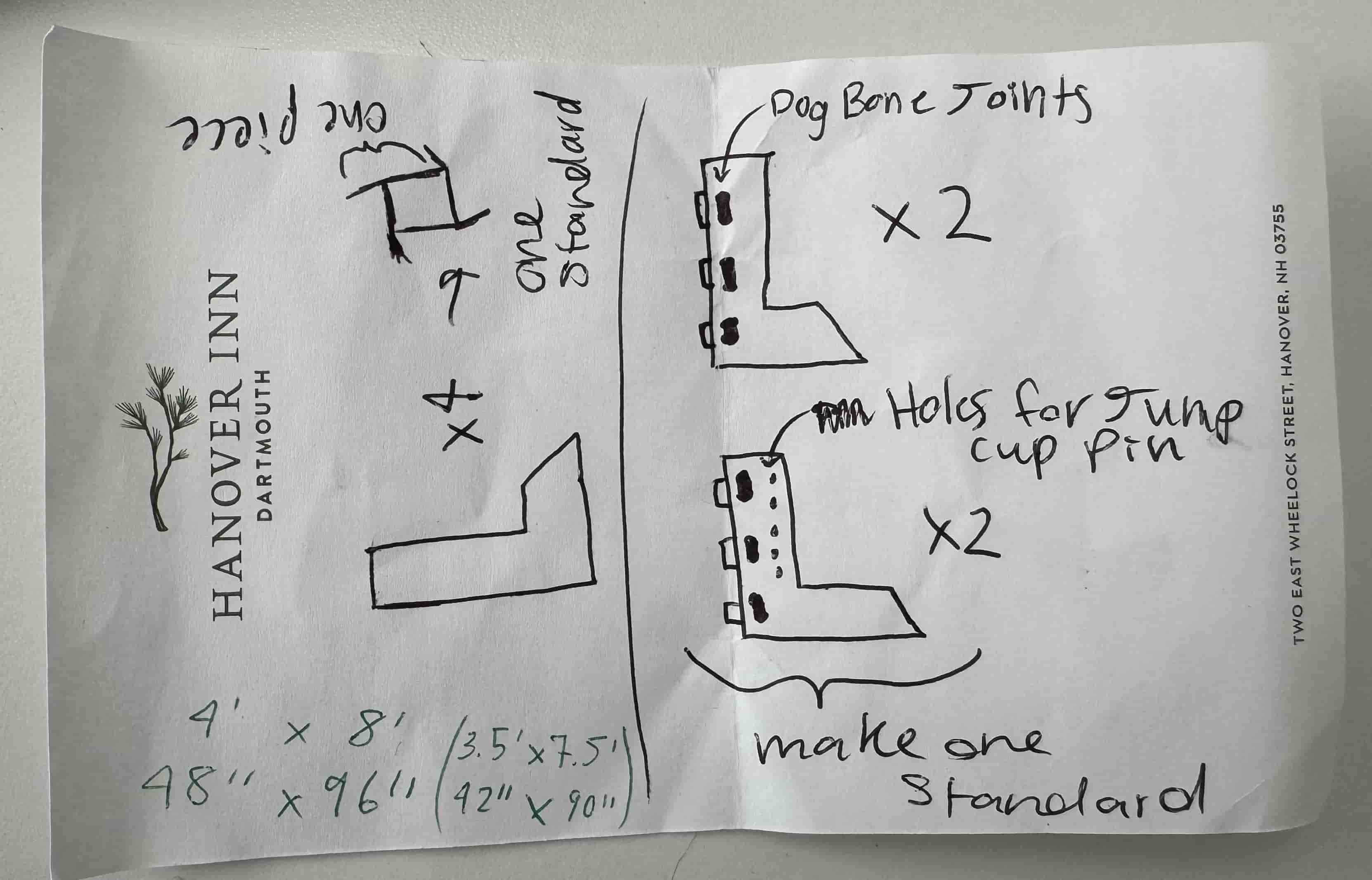
I then watched The Budget Equestrian’s YouTube tutorial and Caroline’s YouTube tutorial for making horse/people jumps.
I then drew these sketches for what I was planning to design in Fusion360:


CAD-ing: Designing in Fusion360
When considering the height of the jump standards, I thought to the typical maximum height of a hunter/equitation horse jump, 3‘6”. Although this would be the ideal height for my standards, I decided to make them 3’ instead as I wanted some wiggle room (as Vaneza suggested) for my cut on the 4’ x 8’ plywood we were provided.
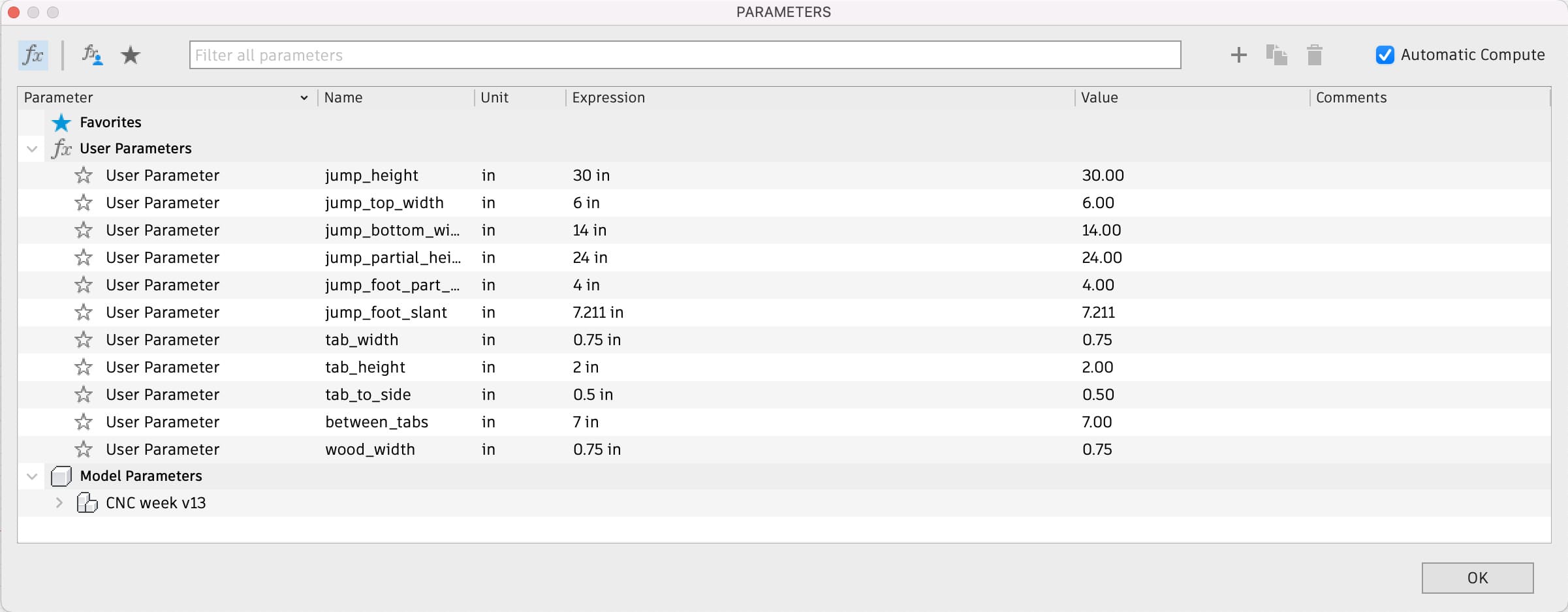
To create my design I opened Fusion360 and created a new file. The first thing I did was make a sketch of the general shape I wanted the standards to be. I then created parameters with dimensions I thought would be a good size and applied them to my sketch (I used parameters that way I could easily change the size of my design later on).
The starting design shape is as follows:

Next, I needed to consider how to make these flat pieces constructible into a sturdy, 3D object. As my peers had success with the dog bone joint, I opted to use them. However, the dog bones did not have to be added in my Fusion360 design as Aspire has a dog bone tool. After referencing Mr. Budzichowski’s documentation I landed on tabs of width 2” and height 0.75” that would be 0.5” away from the edges of the standards and 7” apart from other tabs (the height is dependent on the thickness of the wood).

I need 4 pieces with tab-slots and 4 pieces with tabs so I copied and moved my existing sketch design so that I had the desired amount of pieces all in the same sketch. I then extruded the design by the wood thickness parameter. Next I created a sketch with a rectangle the size of the plywood (48” x 96”) and ensured that my final design fit into the rectangle with some room to spare.

I then exported the file as a .dxf file.
CAM-ing: Aspire (+ creating a toolpath)
CAD File –> Aspire
CAM-ing was a fairly new concept for me so I started by reading through other Fab Academy student’s documentation.
After reading through what other’s had done, I realized that I needed to be in the lab to be able to make my Fusion360 design file into an Aspire file, adding a big time constraint to my work.
Once I was back in the lab, I tried opening my .dxf file in Aspire but the design was not showing up properly.
I remembered seeing that Mr. Budzichowski had some trouble with his Aspire file so I went back to his documentation and watched this YouTube tutorial (Prepare a Fusion360 file for Laser Cutting) he had linked. I ended up trying to make a projected sketch of my design in Fusion360, however, I wasn’t able to get it quite right.
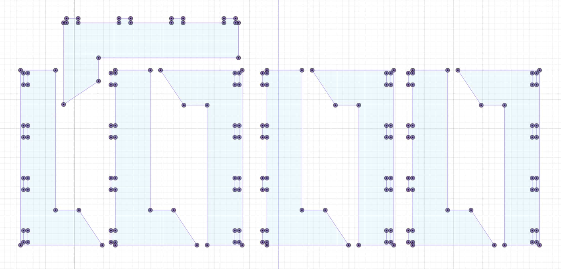
Later, I finally got the Aspire file working. What I had to do was, In Fusion360, I hid bodies, opened my “cnc week standard laser file:1” that I made with Mr. Budzikowski’s linked tutorial, hid the origin, opened sketches, right clicked “sketch 1”, clicked “Save As DXF,” and named it. The main difference (I believe) was that, instead of exporting the entire file as a .dxf, I selected the projected sketch I made specifically and saved/exported it as a .dxf file.
I then opened this file in Aspire and it looked normal!!!
*I highlighted the whole design and used the arrow keys to move it to the center of the material. By later specifying my job size in Aspire and importing the .dxf files of my Fusion360 design, I was able to take my 3D design from Fusion360 to a sketch on the 48” x 96” material in Aspire. When you set up the Aspire toolpaths you specify how deep you will go into the material in the tool, so the z dimension in the 3D design of the Fusion360 design doesn’t really affect anything besides helping you visualize what and how you want to mill.
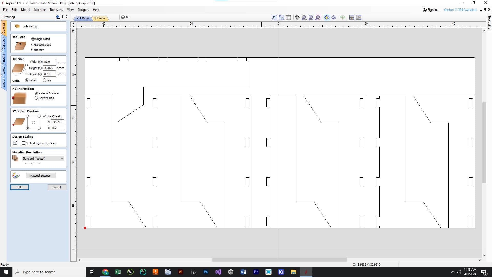
Aspire file Setup
While finishing setting up aspire file, followed mainly Angelina’s site but also Mr. Budzichowski’s. I also read through Landon’s, but I didn’t use it as much in the actual Aspire file set-up.
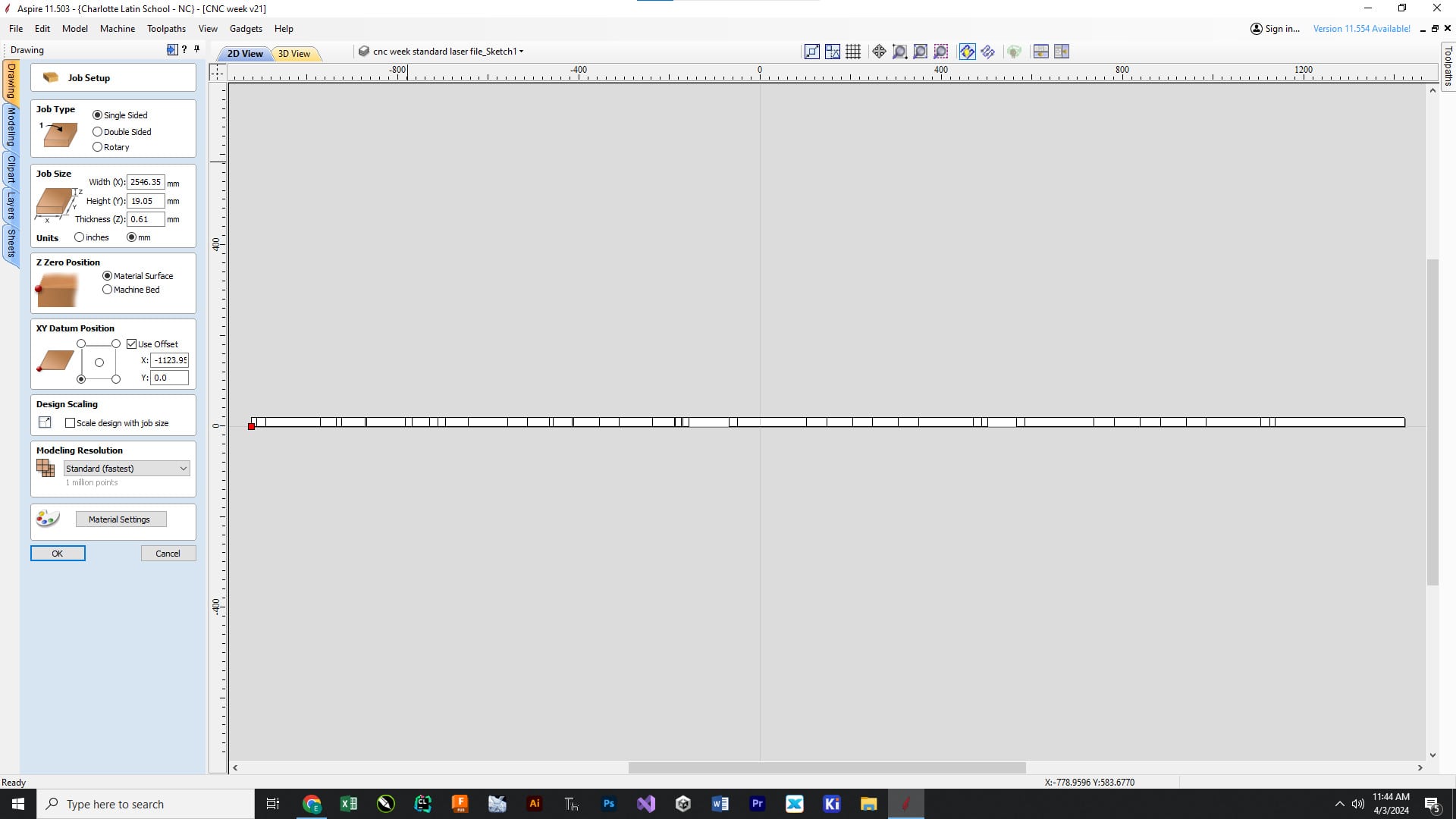
In Aspire in the “Job Setup” tab, I selected the following settings:
-
Job Type: Single Sided
-
Job Size: Width (X) = 96 inches; Height (Y) = 48 inches; Thickness (Z) = 0.45 inches
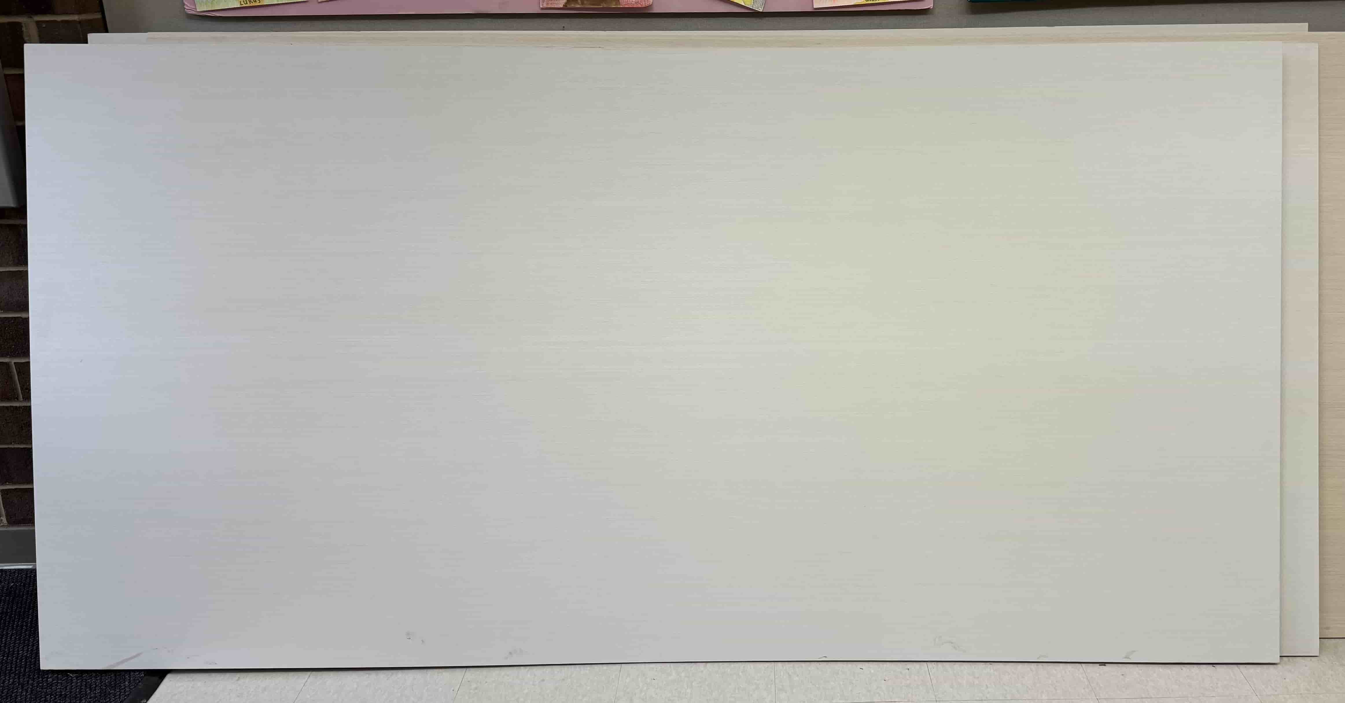
*width and height are determined by my material’s size and the thickness is the thickness of the material (always measure the thickness with calipers in multiple places… manufacturer’s wood thickness is oftentimes not the exact value they state, my wood was ~supposedly~ 0.5 inches… it was 0.45 inches in reality :/)
My material:
-
Units: inches
-
Z Zero Position: Machine Bed
-
XY Datum Position: from bottom left corner and unchecked “Use Offset” box
-
Design Scaling: Unchecked “Scale design with job size” box
-
Modeling Resolution: Standard (fastest)
I then clicked “OK”
Dog-Bone Fillets
Under the “Design” tab, I selected the “Fillet” tool under the “Edit Objects” section. I set the Fillet/Tool Radius to 0.125 inches. I then selected the “‘Dog-Bone’ Fillet” under the “Fillet Type” section. I then clicked on the corners of all of the tabs in my design to give them dog-bone fillets.
Toolpaths
Next, I selected the “Profile” icon and set up a profile cut for the outline of my jump standards.
My settings were:
-
Cutting Depths: Start Depth (D) = 0.0 inches; Cut Depth (C) = 0.45 inches
-
Tool: 3/8” Compression Spiral; Passes = 3
Note: I increased the suggested passes number by one for my toolpaths to ensure I did not break the bit
-
Machine Vectors: Outside/Right; Direction = Climb; Allowance offset = 0.0 inches
-
Unchecked “Do Separate Last Pass” box
-
Checked “Add tabs to toolpath box”; Length = 0.75 inches; Thickness = 0.125 inches
*I added about one tab to each side of the outline
- Ramp: unchecked “Add ramps to toolpath” box
I then clicked “Calculate”
Next, I I selected the “Pocket Toolpath” icon to create a pocket cut for the dog-bones.
My settings were:
-
Cutting Depths: Start Depth (D) = 0.0 inches; Cut Depth (C) = 0.45 inches
-
Tool: 1/4” Straight (Onsruf 48-005)
-
Passes: 2; Offset selected; Cut Direction = Climb; unchecked “Ramp Plunge Moves” box
Note: I increased the suggested passes number by one for my toolpaths to ensure I did not break the bit
- Pocket Allowance: 0.0 inches; unchecked “Use Vector Selection Order” box
I then clicked “Calculate”
- Note: for my tool’s feed rates, they were left as default as I did not change any specific settings in the tools that I used. According to a forum post on Vectric’s website, “The feed rates are part of the tool you select from the database when you create the toolpath. You can change them in the tool database (you must then re-select the tool) or use the Edit button in the toolpath itself to change them just for that toolpath.”
*I had an instructor double-check my file BEFORE proceeding to CNC-ing (our lab requires this and I recommend always having a second set of knowledgeable eyes look at your Aspire file… no need to risk breaking the expensive, complicated ShopBot!)
CNC-ing
While CNC-ing, I followed Our lab’s ShopBot Alpha ATC Routines Document and Angelina Yang’s Workflow for CNC-ing. Furthermore, Garret helped me immensely through the CNC process :)
CNC Workflow
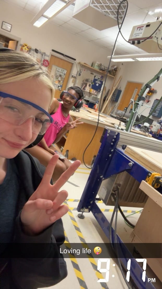
1. Setup/Safety
-
Get & put on your eye and ear protection!
-
Get a friend to be in the CNC room with you and have them put on eye and ear protection (trust, you wanna keep your sight/hearing)
My friend :) Dariyah!
-
Ensure the start of day routine has already occurred/the machine is warmed up – check with an instructor if you’re not sure… DON’T wing it and break the machine
-
Put the material you will be cutting on the machine bed, aligning it to the bottom right corner of the bed
-
Secure the material to the bed, I used brad nails (put forethought into their placement, try to make it so the spindle won’t hit them (it’s okay if it does though with brads, it’s just not preferable))
2. Aspire software
-
Open Aspire
-
Open your design file in Aspire
-
Select the objects you want to cut
-
Select the appropriate toolpaths
3. Go to Material Setup
-
Ensure that “machine from bed” has remained selected
-
Ensure that material thickness has remained what you set it to
-
Click “OK”
4. Go to Tool Path Operations
-
Select “2D Profile Toolpath”
-
Preview toolpath
-
Click “Close”
-
Click “Save Tool Path” and save it in the ShopBot format
5. Open the ShopBot Command Console
6. Run an Air Cut
-
Click “File” and “Load” and select your file that you just saved
-
Type “JH” to bring the spindle to the origin
-
Set the z-height to 1 inch above the material (JZ 1)
-
Type “Zz” (zero-z-axis) so that the z-axis zeros and this 1 inch above the material height becomes a temporary origin above the material
-
Ensure there’s no offset
-
Start the spindle by clicking the green button & run the file
-
Observe the air cut and ensure it’s occurring as the toolpath simulation showed
-
Once done, type “C3” to rehome and reset the z-zero height to the machine bed by typing “Zz”
Note: the C3 command zeros the XY axes off of the proximity switches – as according to ShopBot
An additional note on homing:
According to ShopBot, for Maintaining Accurate XYZ Locations, “You should be aware that both the Table Base Coordinates and Working Coordinates remain accurate only as long as your tool is not manually moved. Your tool can be manually moved either by pushing it with the motors off, or by having it accidentally pushed when the computer and software are not operational. When the software is running normally, the motors are on and the tool will be securely locked in position. However, when the motors are off, it is vulnerable to being inadvertently moved and there is no way for the software to know that this has happened. Thus, you should be careful that your tool is not pushed or jarred when it is out of use, if you are trying to maintain your location from session to session.
You can use the [C3] Command to Zero the X and Y axes anytime the power has been off, or after any operation where you have moved your Zero point. You can use the [C2] Command and the Z-Zero plate supplied with your tool to Zero the Z axis to either the top of the table or the top of your material.”
For more information on the ShopBot CNC Machine and its workings, visit The ShopBot User Guide.
7. Run Cut
-
Click “File” and “Load” and select your file that you just saved
-
Click the green button to start the spindle (you should hear a sound that indicates the spindle has started)
-
Turn on the vacuum
-
Click “enter” to run the file
8. After the Cut
-
Turn off the spindle
-
Turn off the vacuum
-
Using a chisel, mallet, crowbar, multitool, etc., remove the tabs from the pieces and hit the remove the material/break the brads
9. Clean up
-
Use a broom to collect shavings
-
Vacuum up the shavings
10. End of Day
- If you are the last one to use the ShopBot, run the End of Day Routine
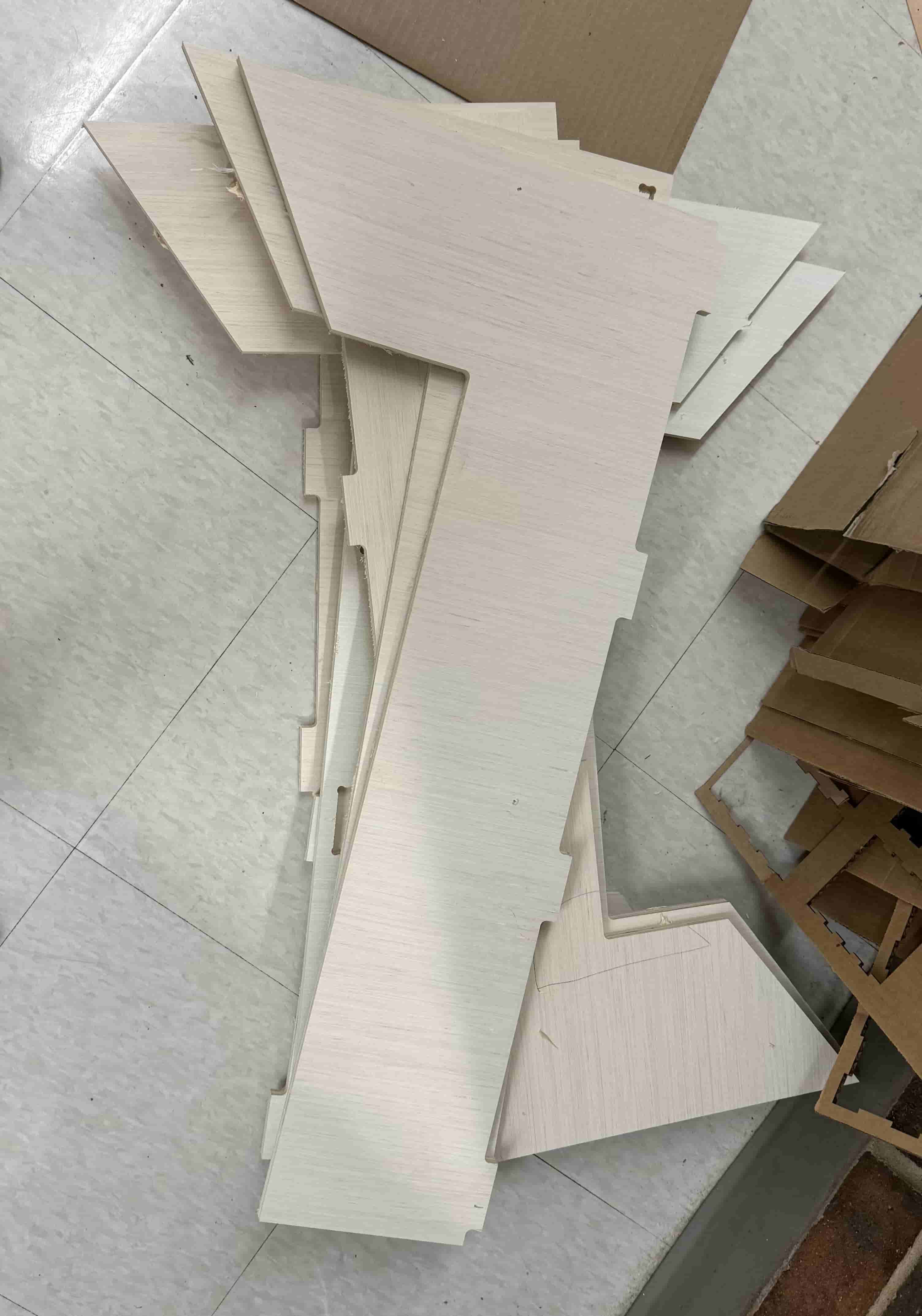
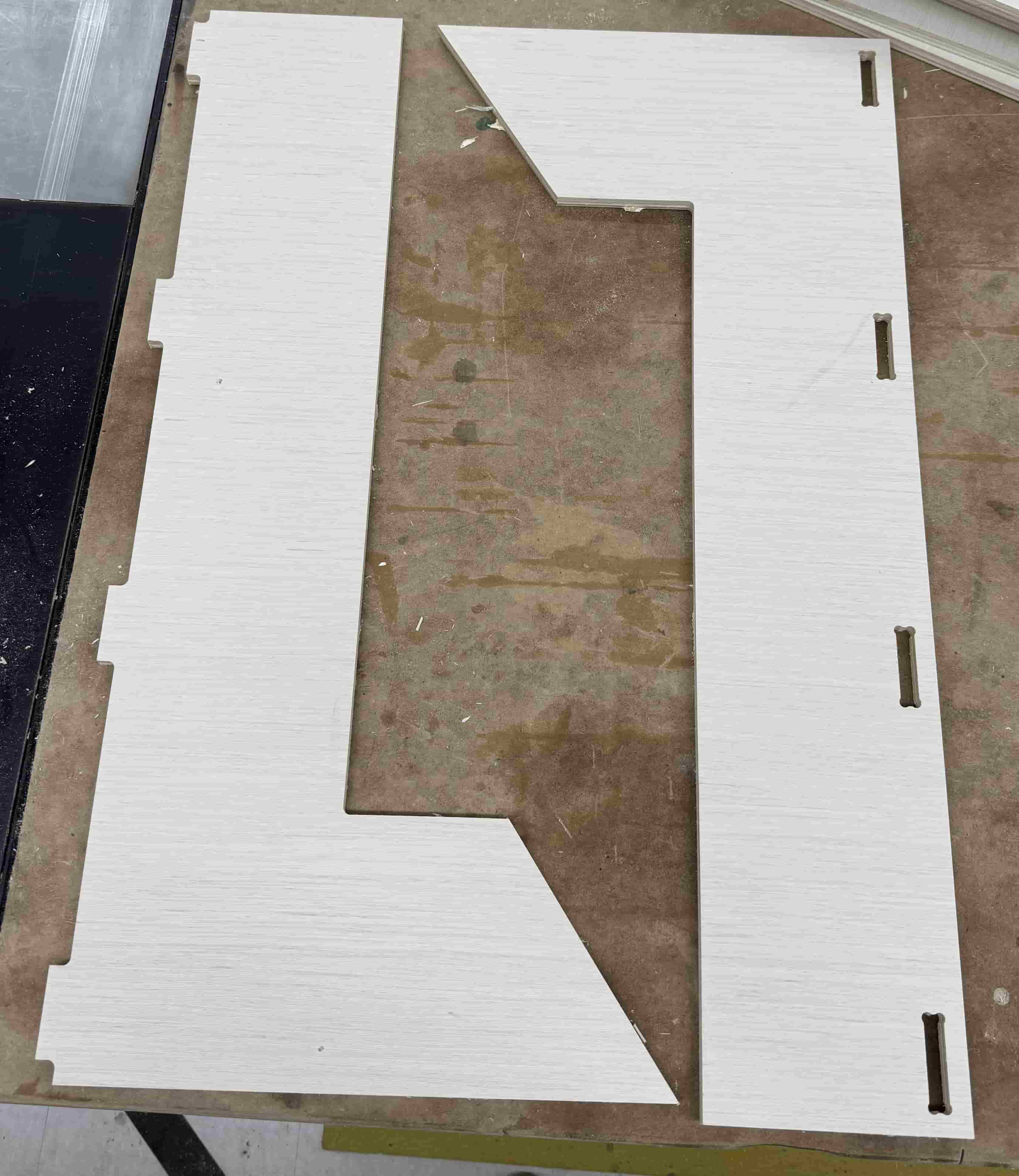
My pieces after CNC-ing:
Sanding
I used an orbital sander and 80-grit and 120-grit pieces of sandpaper to sand my CNC-ed pieces.
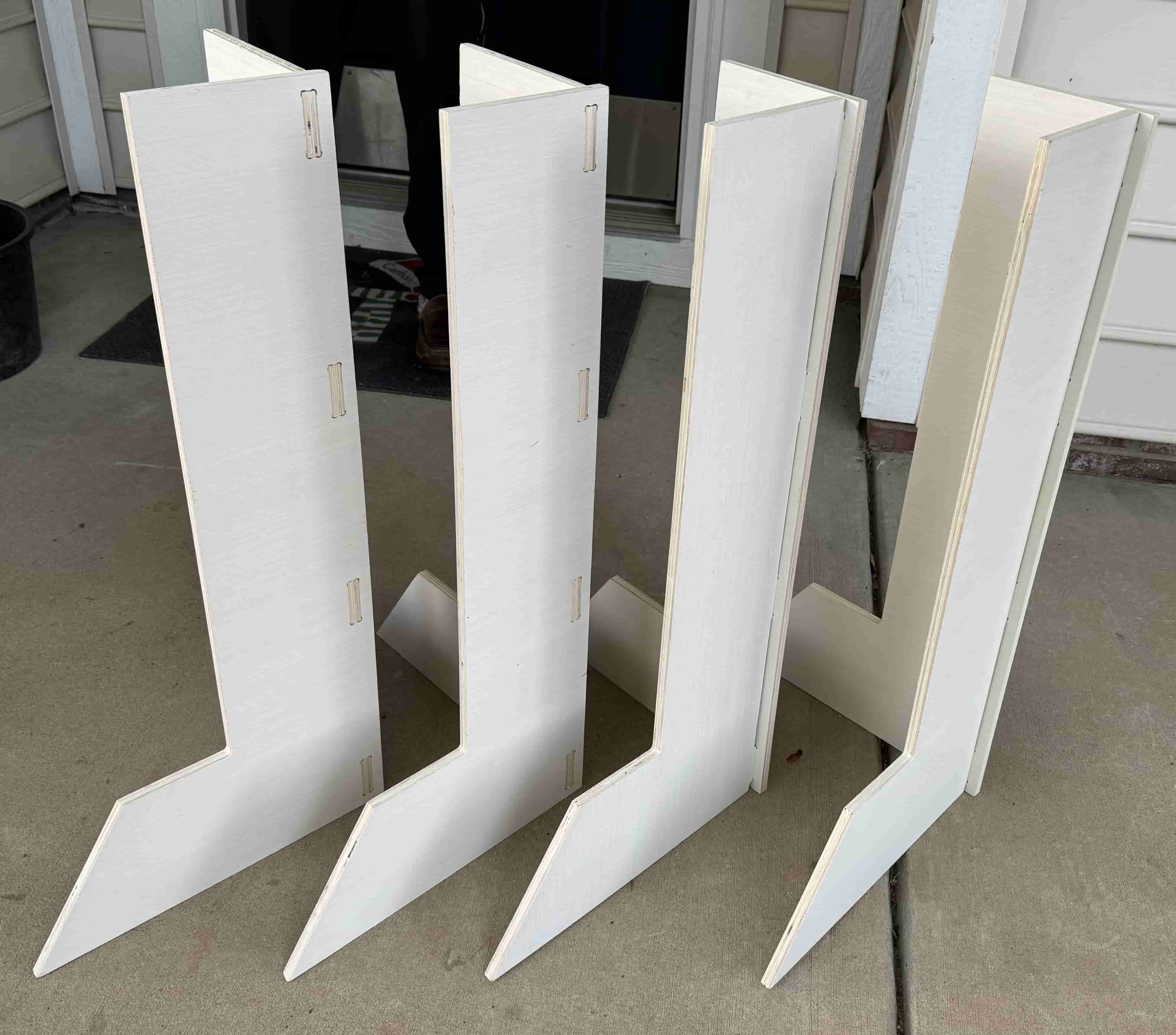
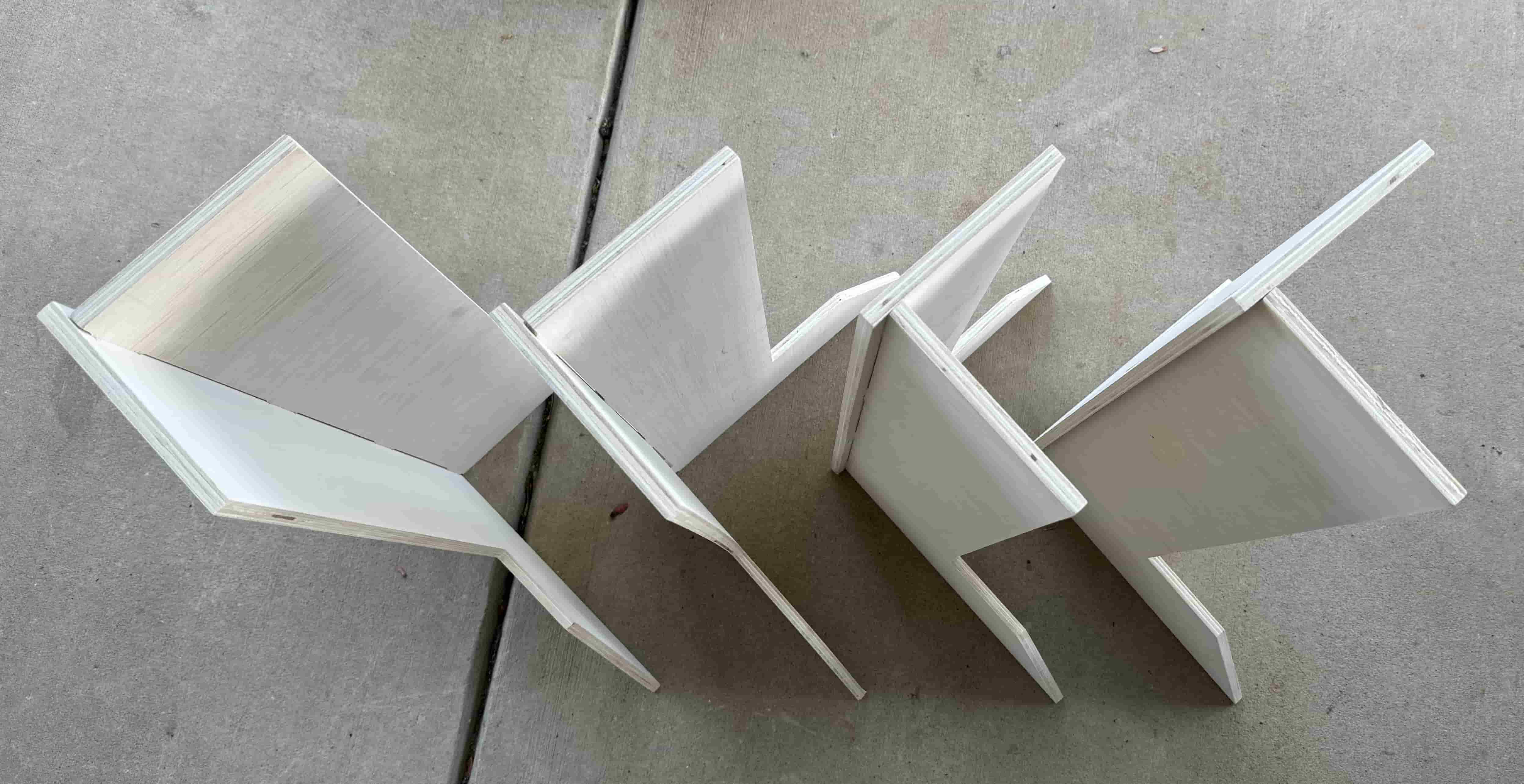
Assembly
Once the pieces were all ready, I lined the slots and tabs up and pushed the pieces together a bit. Once a little together, I used a hammer to firmly secure the pieces together.


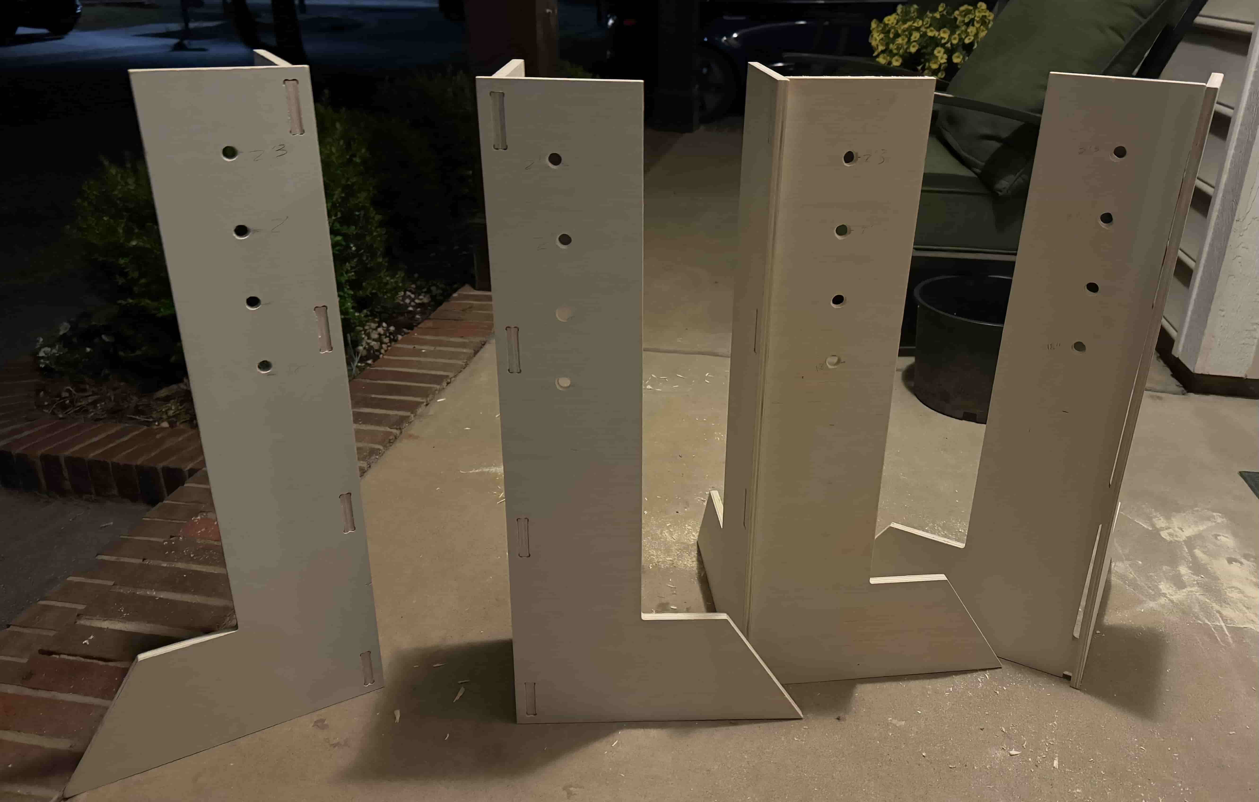
Later changes
Although the current product served the purpose I wanted, I later decided to use a drill to make more holes in the standards so that I would have more heights for jumping. I drilled the holes at heights 15”, 18”, 2’, 2‘3”, and 2‘6”. I then used a dremmel to sand the holes and remove the chipped plywood pieces.
In-Action
Here’s the people jump standards in action! (Don’t laugh too hard please)
Reflection
This week was challenging for me not because of the processes but rather because of time. Between spring break and not being able to come into the lab to getting the stomach flu and not being able to do any work, time was a super big crunch. I had to realize that life happens whether you want it to or not and I just needed to put in the work and overcome it. So, almost 3 weeks later, it finally got done. It’s not ideal, but it’s done and that is so valuable!
Blood, Sweat, and Manyyyyyy Tears
Enjoy a pic of me lugging the CNC-ed pieces, machine week supplies, my school bag, lunch, and toolbox:

I had to walk a quarter mile like this :’(
arms felt very buff the next day though :)
References
-
https://docs.google.com/presentation/d/1pwJQbAnV0YFZIChueT52yMBPWJK4XfUPXP-yQWqRTVg/edit?usp=sharing
-
https://docs.google.com/document/d/13KMj7j8VIOVJ1x5KJyU1tCYY6a3ldDfN6Uc6bT5ok20/edit?usp=sharing
-
https://fabacademy.org/2023/labs/charlotte/students/zack-budzichowski/assignments/week07/
-
https://fabacademy.org/2024/labs/charlotte/students/landon-broadwell/assignments/week08/