4. Electronics Production
Group Assignment:
- characterize the design rules for your in-house PCB production process
Individual Assignment:
-
make and test a microcontroller development board
-
extra credit: personalize the board
-
extra credit: make it with another process
Download Design Files
Click here to download my design files folder
Group Work Reflection
From my group work I learned the value of explaining/teaching concepts to others to better understand them yourself. One of my group members was absent the day we originally worked on this week’s assignment so I helped him get back to speed and understand what we were doing. From explaining the component organization system and how to navigate and understand our given resources to simply pointing out where the bits were stored, explaining the processes really helped cement the concepts in my mind.
Workflow for sending a printed circuit board (PCB) to a board house:
Making and Testing a Microcontroller Development Board
Milling
Our lab’s milling machine is an OtherMill Pro. We use the Bantam Tool’s Milling Machine Software.

To start the microcontroller production process, we first walked through the milling process. We then milled 4 boards at a time, taking turns setting up the file and observing the milling. I used our group workflow (can be found at this link.)
I later milled by myself doing the following:
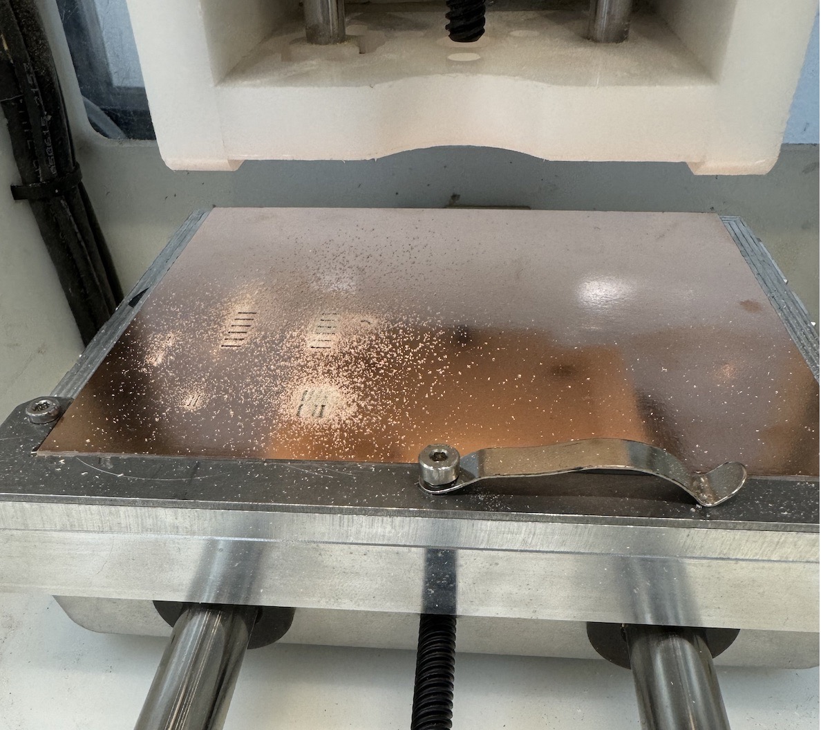
I took a copper plate, applied nito tape evenly on the bottom of the plate, and stuck it in the bed of the milling machine.
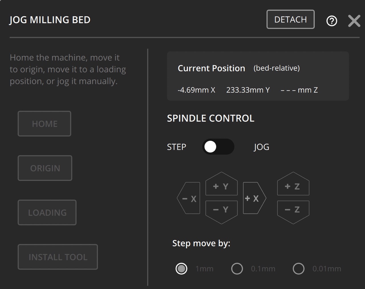
After ensuring the file I wanted to mill was on the PC connected to the milling machine I was using, I opened Bantam Tools on the PC.
When opened, the software looks like this:

I then clicked the “on” button on the back of the milling machine so that it would connect to the computer.
The software then told me that the machine was unhomed.
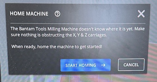
I clicked “Start Homing” – “Homing the machine tells the software where all the parts of the mill are. If you don’t home the mill, you won’t be able to accurately machine your parts” (BantamToolsResources).
The Bantam software automatically homes in the x, y, and z.
In Bantam Tools, I setup the file for milling as follows:
MATERIAL SETUP
I clicked on the box with a circular pointing arrow labeled “MATERIAL SETUP” to open the material setup tab.
Pictures of my settings:
Under “INSTALL TOOL,” I clicked the “INSTALL TOOL” button and followed the prompts. To remove the bit already installed, I removed the front panel, took the two wrenches and turned them in opposite directions (the wrench on the nut higher up turning to the left and the wrench on the nut below the other turning to the right). I then took the bit out and put it away before inserting the bit I needed and tightening it by turning the wrenches towards each other (opposite directions as before). When milling you should start with the smallest bit, so I started with the 1/64” Flat End Mill (Note that you may need to select your milling tools under the “FILE SETUP” tab before installing your tool).
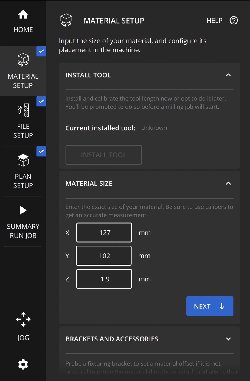
Under “MATERIAL SIZE” I selected the following settings:
X: 127 mm
Y: 102 mm
Z: 1.9 mm*
(*note that the Z value will change depending on the value determined by the milling machine when you probe the board)
I aligned my material to the front left corner, however, the size of the material I used takes up the whole space so aligning to a the left or right, as long as the material touches the front, would not actually affect it.
We did not need to change or do anything with the “BRACKETS AND ACCESSORIES” dropdown.
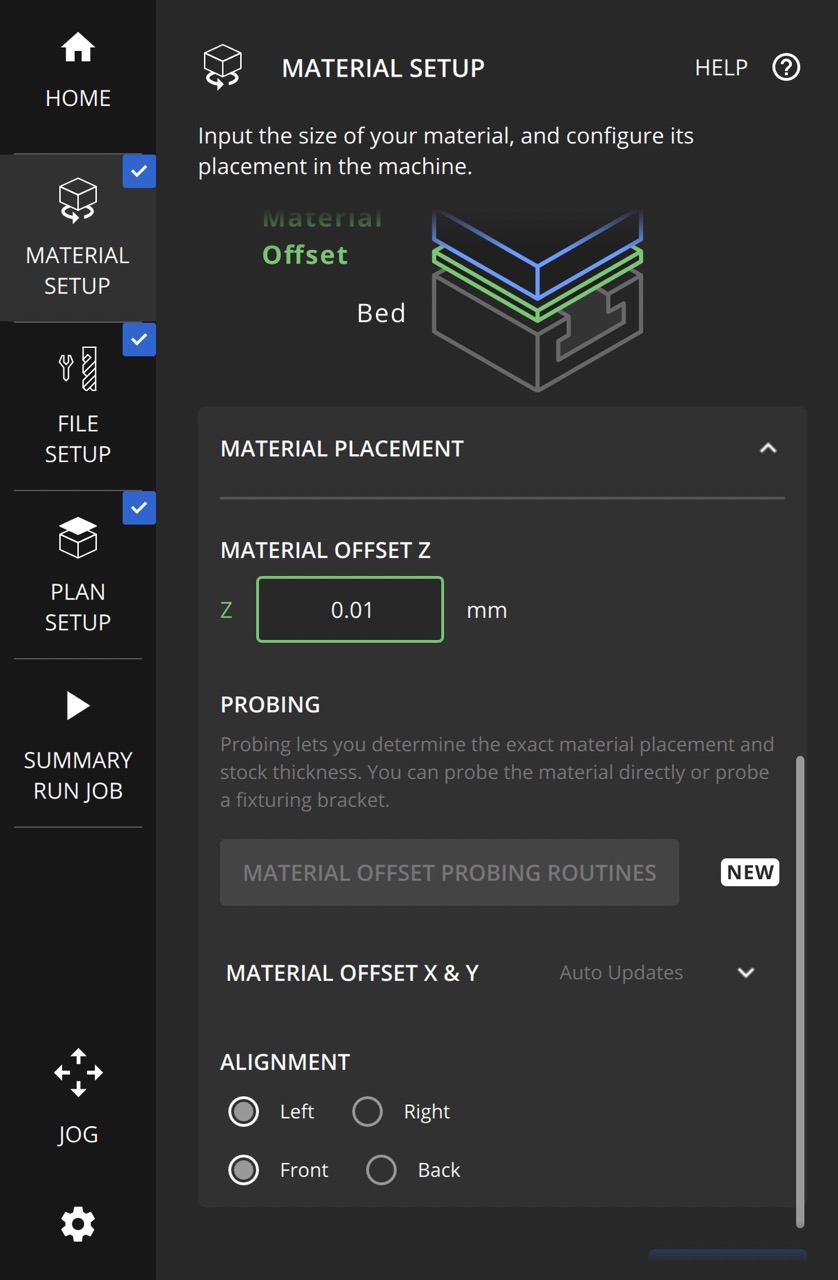
Under the “MATERIAL PLACEMENT” dropdown I selected the following settings:
Material Offset Z
z: 0.01 mm
Material Offset X & Y
X: 4 mm
Y: 4 mm
Alignment
Left: selected
Front: selected
FILE SETUP
I clicked on the bit icon labeled “FILE SETUP” to open the file setup tab.
Pictures of my settings:
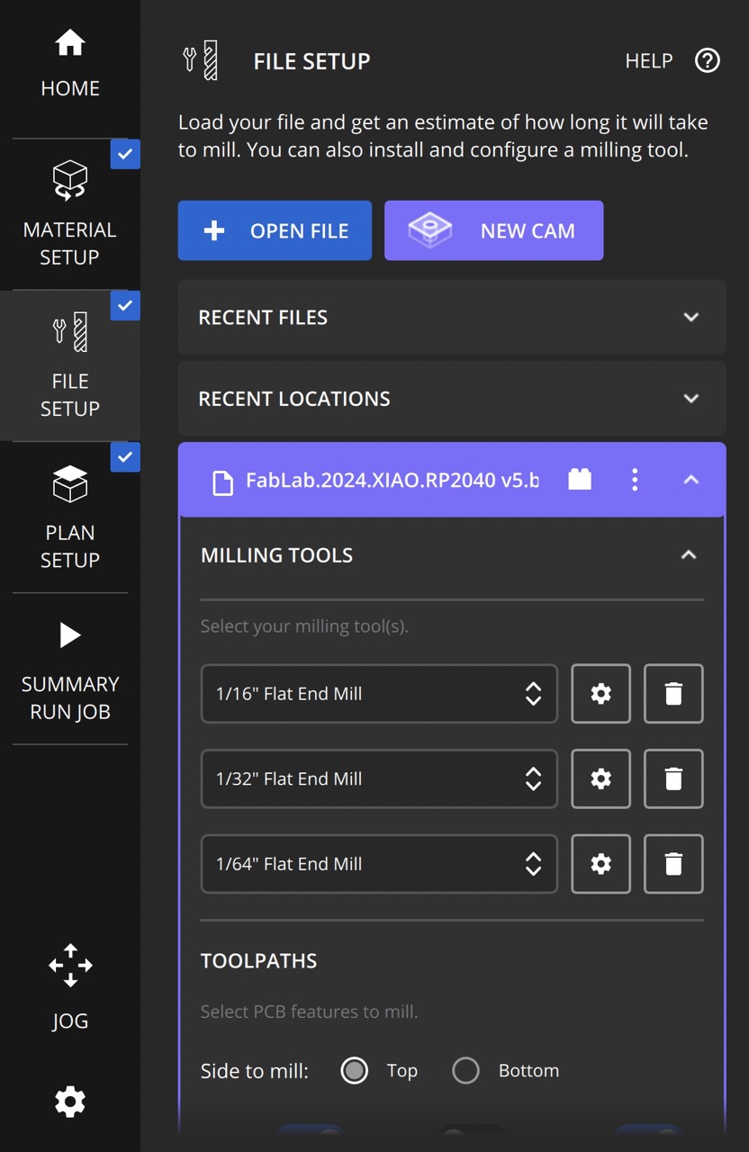

I then opened this file I was milling. I then clicked the dropdown to open the “MILLING TOOLS” section. I then selected the following three tools:
1/16” Flat End Mill
1/32” Flat End Mill
1/64” Flat End Mill

Note:
- I use three different tools to successfully and efficiently mill my board. Some areas in the milling require smaller bits, such as the 1/64” flat end mill. If I were to use a larger bit, like the 1/32” flat end mill or 1/16” flat end mill, the milling machine would remove too much material and the trace would either be extremely small and weak or nonexistent. Technically I could just use the smallest bit required for the entire board, however, this would take a much longer time than using multiple bits of varying sizes. Using some larger bits allows me to take off a large amount of material faster than with a smaller bit that would have to do multiple passes.
I then scrolled down to the “TOOLPATHS” section and selected the following settings:
Side to mill: Top
Traces: on
Holes: off
Outline: on
Trace Depth: 0.15 mm
Trace Clearance: 1.5 mm
Use Detail Tool Everywhere: off
Rotation: 0 degrees
Then I clicked the “GENERATE GCODE NOW” button.
Notes:
- Trace Depth is “the distance in the z-axis that the end mill will cut
..As you cut deeper, the V-shaped engraving bit will cut a wider path. If the Trace Depth is changed from the default to a larger value, the same cutting tool might become too large to cut the board.
Likewise, if you reduce the Trace Depth setting, the engraving bit will cut a narrow path”
(source).
Due to this, at my lab we generally keep the trace depth as the default setting.
Also, as my global evaluator pointed out, the thickness of the copper in my PCB is <0.15 mm. Thus, as I want to remove the whole layer of copper in my PCB, I used this value.
- Trace Clearance “distance refers to the distance between a trace and any conductive material that is not part of the same electrical circuit” (source). They recommend “a minimum spacing of 1.5mm (60 mil) between components and adjacent traces to prevent heat transfer issues during soldering.”
In more plain terms, trace clearance is the minimum distance between conductor traces and, when specified in BantamTools software, is “the amount of material removed around all traces and pads” (source). When two different traces touch, they can cause shorts or have unintended results on the function of the PCB. Thus, it is important that the traces stay to themselves. This is why it’s important to consider the necessary distance between traces so that heat transfer does not become an issue for the PCB’s function. My lab recommends a trace clearance of 1.5 mm and that’s the value I generally use.
PLAN SETUP
I clicked on the box with a white square above it icon labeled “PLAN SETUP” to open the plan setup tab.
Picture of my settings:
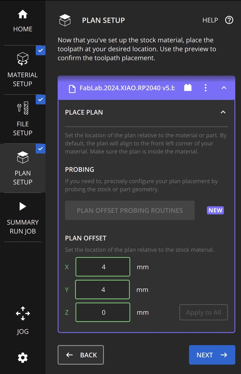
I changed the X and Y values from 0 mm to 4 mm. Doing this makes it so that the machine does not mill too close to the outside of the copper sheet and mess up the mill or break the bit/machine.
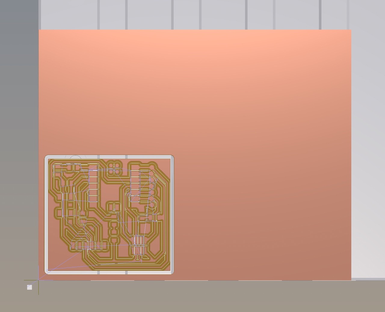
Here’s what the BantamTool’s Simulation looked like:
SUMMARY / RUN JOB
I clicked on the arrow icon labeled “SUMMARY / RUN JOB” to open the summary and run job tab.
Picture of my settings:
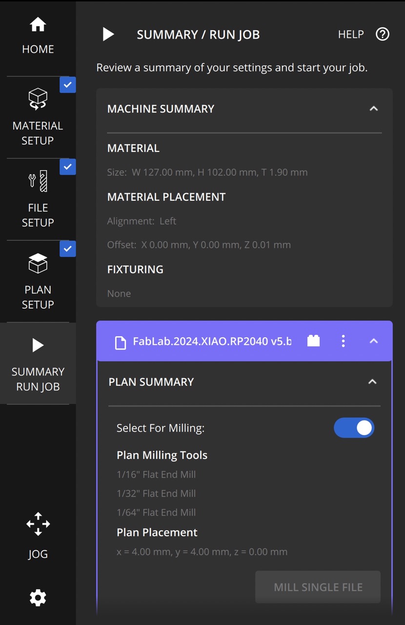
I looked over the “MACHINE SUMMARY” and “PLAN SUMMARY” details to ensure they were right. Under “PLAN SUMMARY,” “Select For Milling:” should be turned on. I then clicked “MILL SINGLE FILE” to start the mill.
Once the mill had finished, I clicked “jog” and “loading” to move the bed forwad so that I could use the vacuum to clean the excess copper off the board and machine.
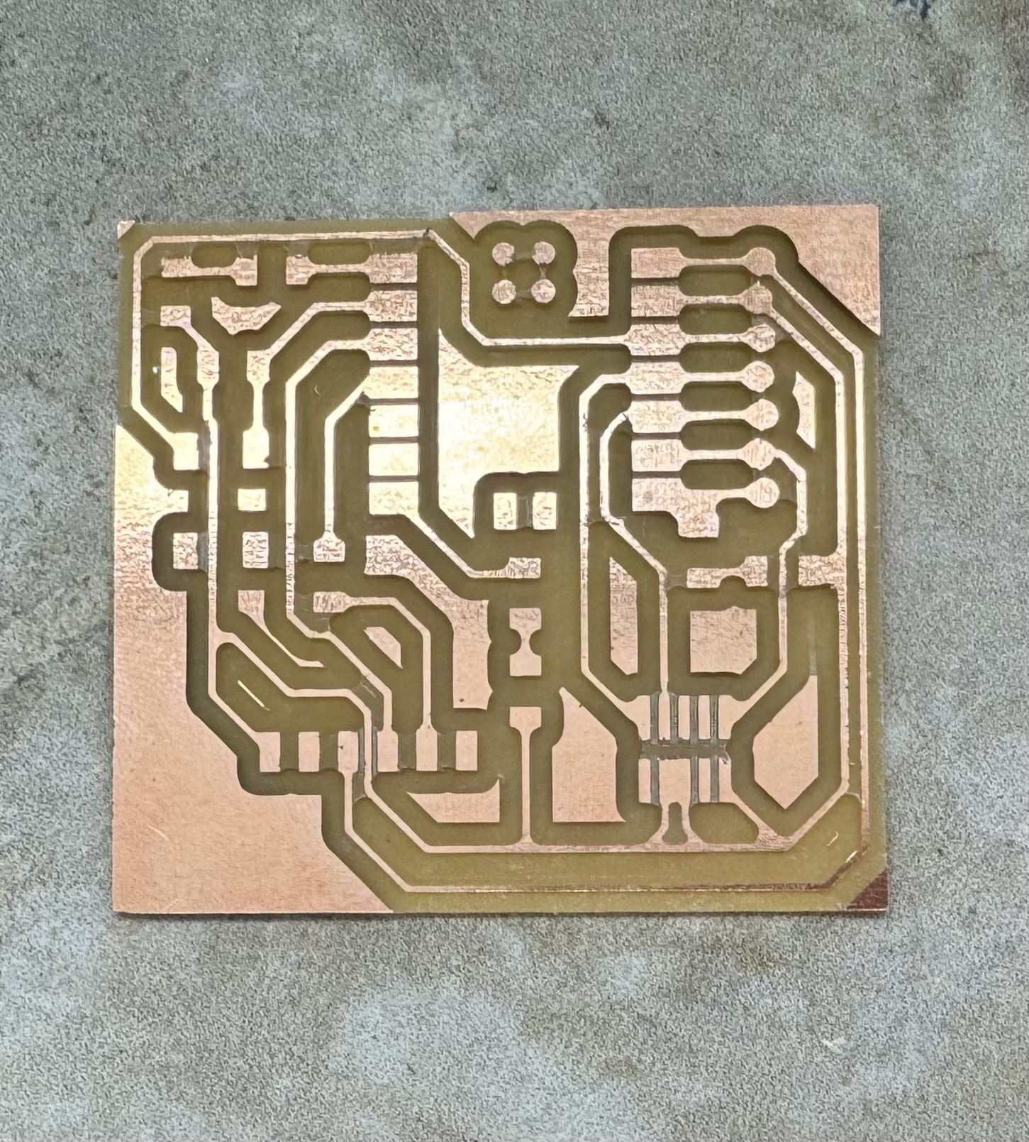
The Milled Board:
Milling Problems Encountered:
-
Shortage of some bits; ended up using a “PCB Engraving Bit 0.005 in” bit instead of the 1/64 bit others were using
-
Needed to turn off the holes option for the design
-
Machine would prompt me to change the bit, I would do so, click “resume,” and nothing would happen. To overcome this, I had to cancel the milling, go back into the file setup, delete the bit I was just using from the “milling tools” tab, re-download the g-code, and then click “mill single file” again.
-
Rubber bands broke on the milling machine, Mr. Durrett taught us how to replace them
-
Confusing with changing the bit… have to turn the bolt left to tighten it
Component Collection
Before we could begin soldering we needed to gather all necessary components. Mr. Dubick and Mr. Durrett helped me understand the Charlotte Latin Fab Lab’s component organization system and how to interpret the component names.
Necessary Components:
Component Collection Problems Encountered:
-
Originally grabbed a larger header than needed, had to go back and get the correct one
-
Had trouble locating the headers in the lab organization system
-
Although the file we milled a board for was labeled as the “february” file (version of the Quentorres created by Dr. Taylor), the files were mislabeled and we actually milled the “january” file. I originally got a 0 ohm resistor as the “february” board needed them, however, the “january” board did not.
-
Figuring out how to read/interpret component names was rather difficult
-
Components were small and easy to lose; Mr. Dubick had us tape them down on a blank sheet of paper and write their names next to them so that we wouldn’t confuse or lose components
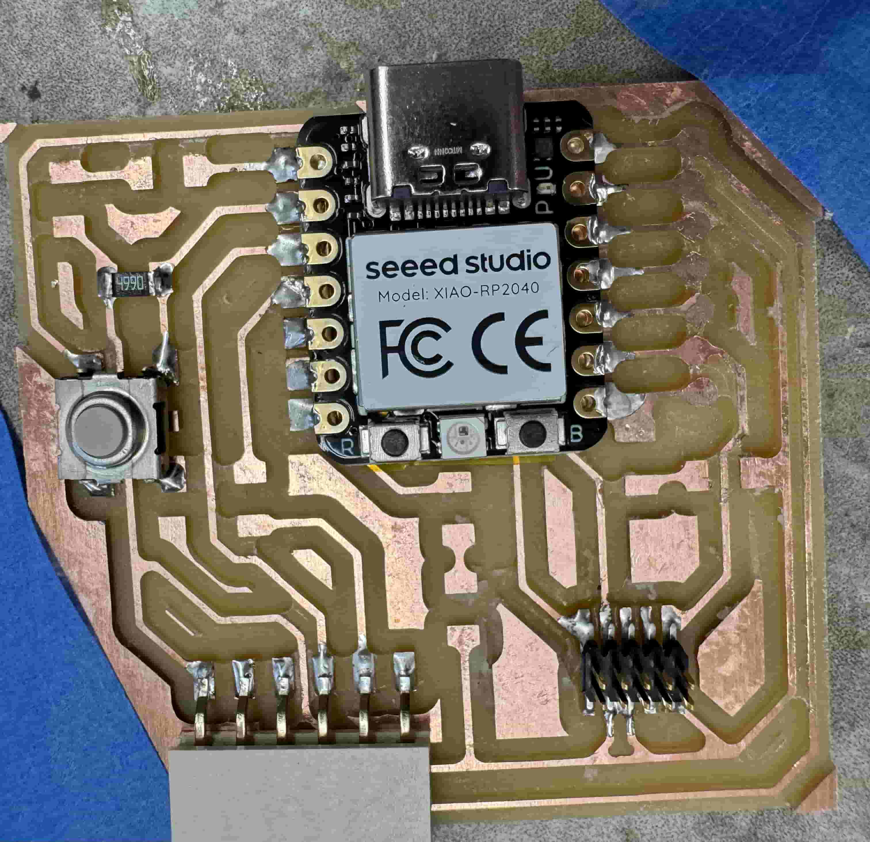
Soldering
For soldering the PCB board, I first taped the board down (ensuring I didn’t tape over any essential traces and risk damaging them). Next, I took my soldering iron and changed them temperature from 750 degrees fahrenheit to 650 by holding the “ENTER” button down until the temperature display was blinking, then clicking the “UP” button until the first digit reads “6,” and then clicking enter until the display lights return to a steady color. I then cleaned the tip of my soldering iron until it was shiny. I then put kapton tape on the bottom of my RP2040 and soldered it onto the board.

Next I plugged in the RP2040 to ensure that it worked before I soldered anything else; the lights turning on indicated that it worked.

Soldered on the Conn Header SMD R/A 6POS 2.54MM
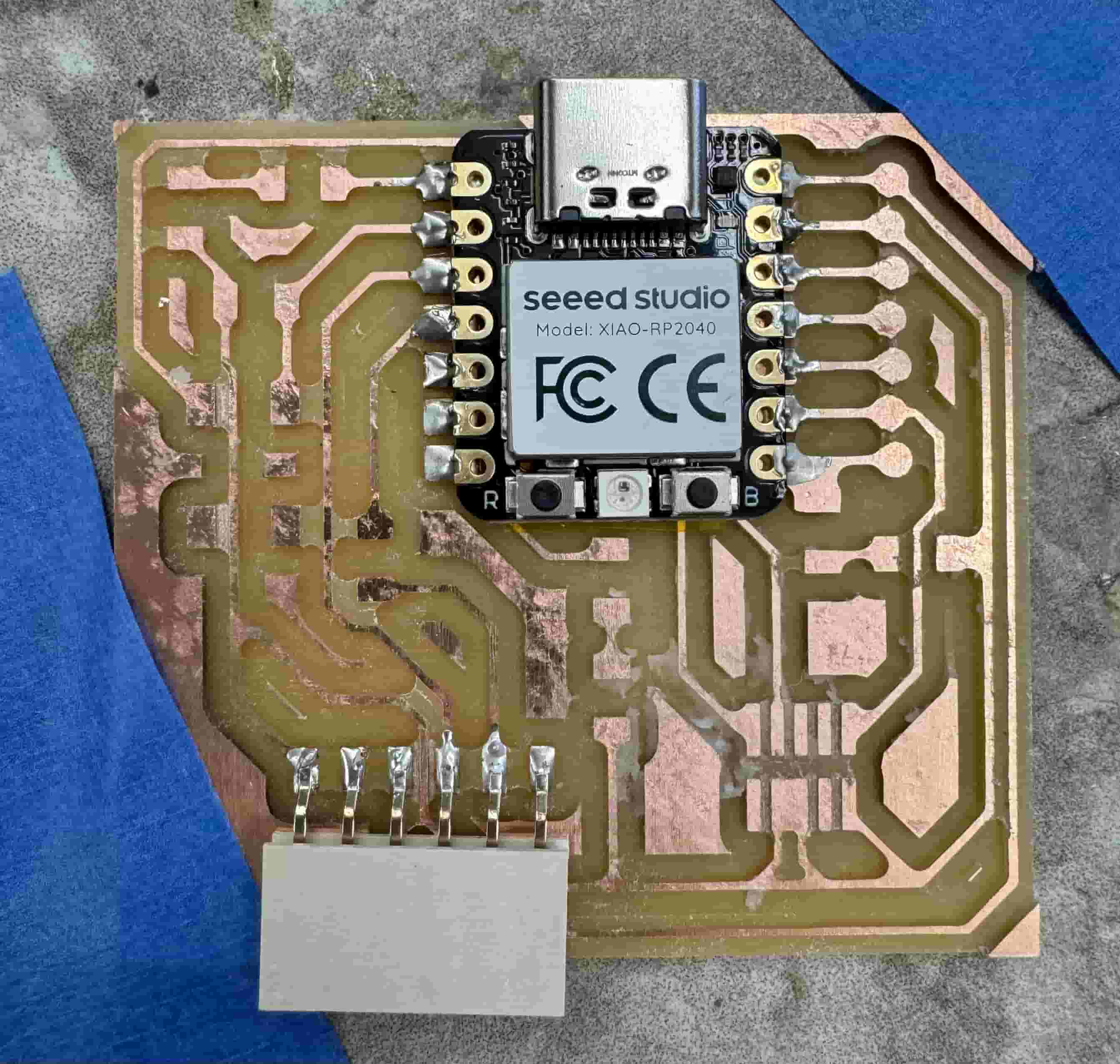
Soldered on the Conn Header SMD 10POS 1.27MM

Soldered on the Tactile Switch SPST-NO Top Actuated Surface Mount (button)
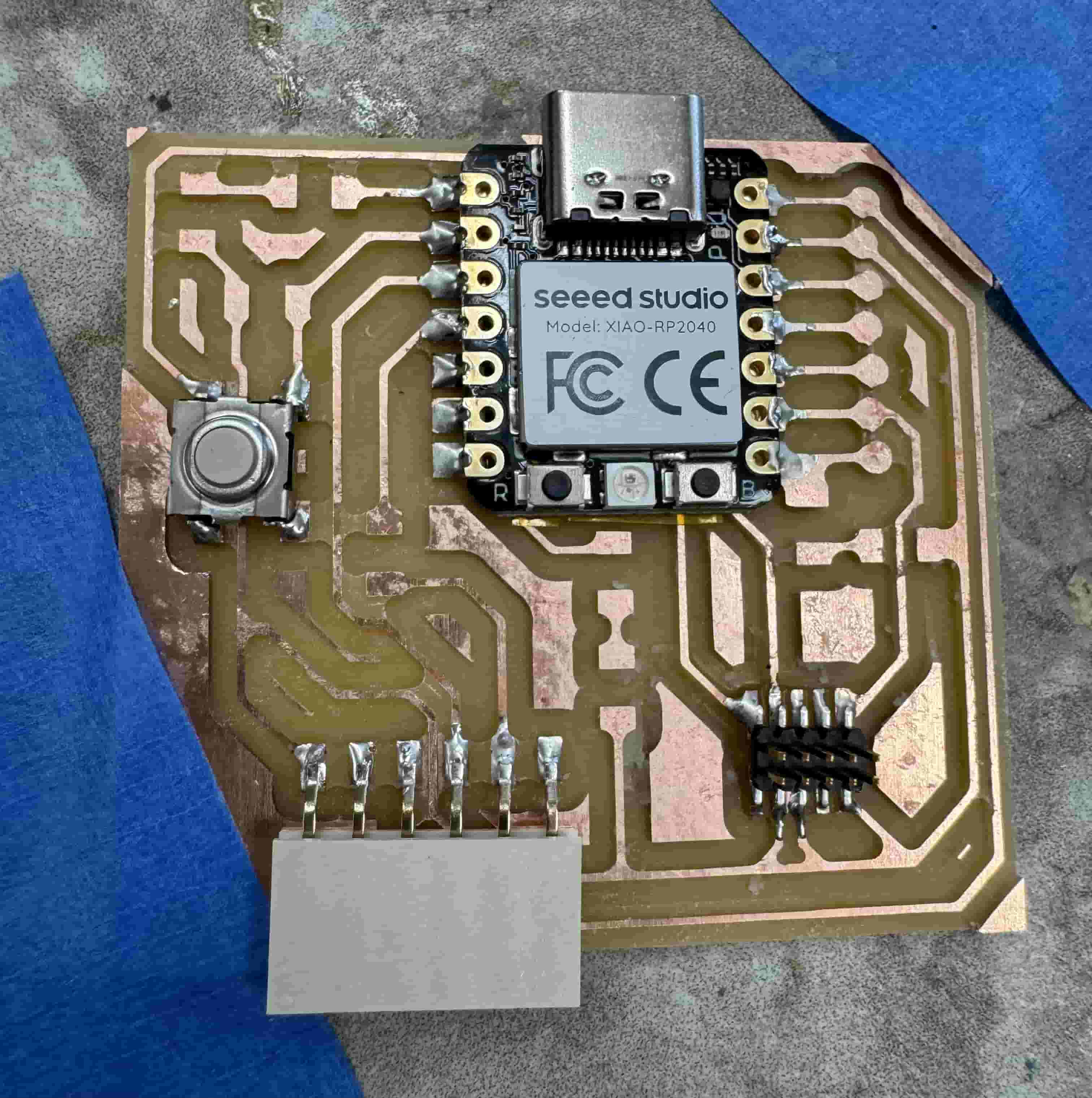
Soldered on the RES 499 OHM 1% 1/4W 1206
Soldered on the RES 1k OHM 1% 1/4W 1206
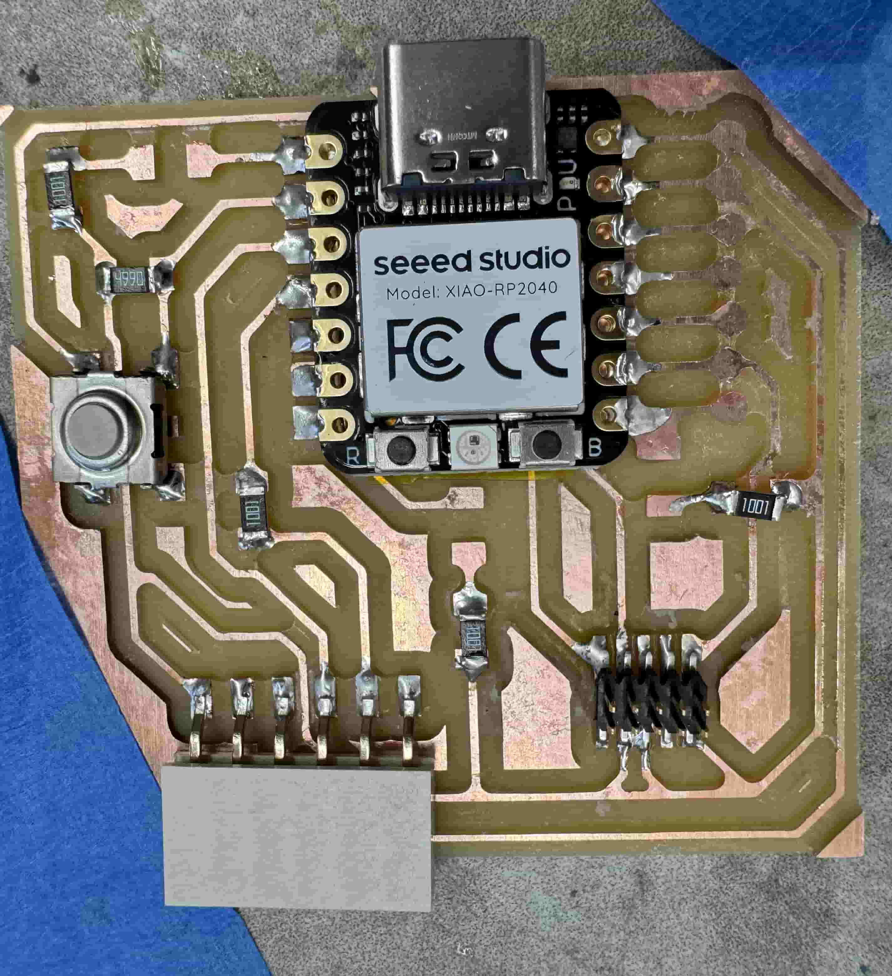
Soldered on the 3 LEDs
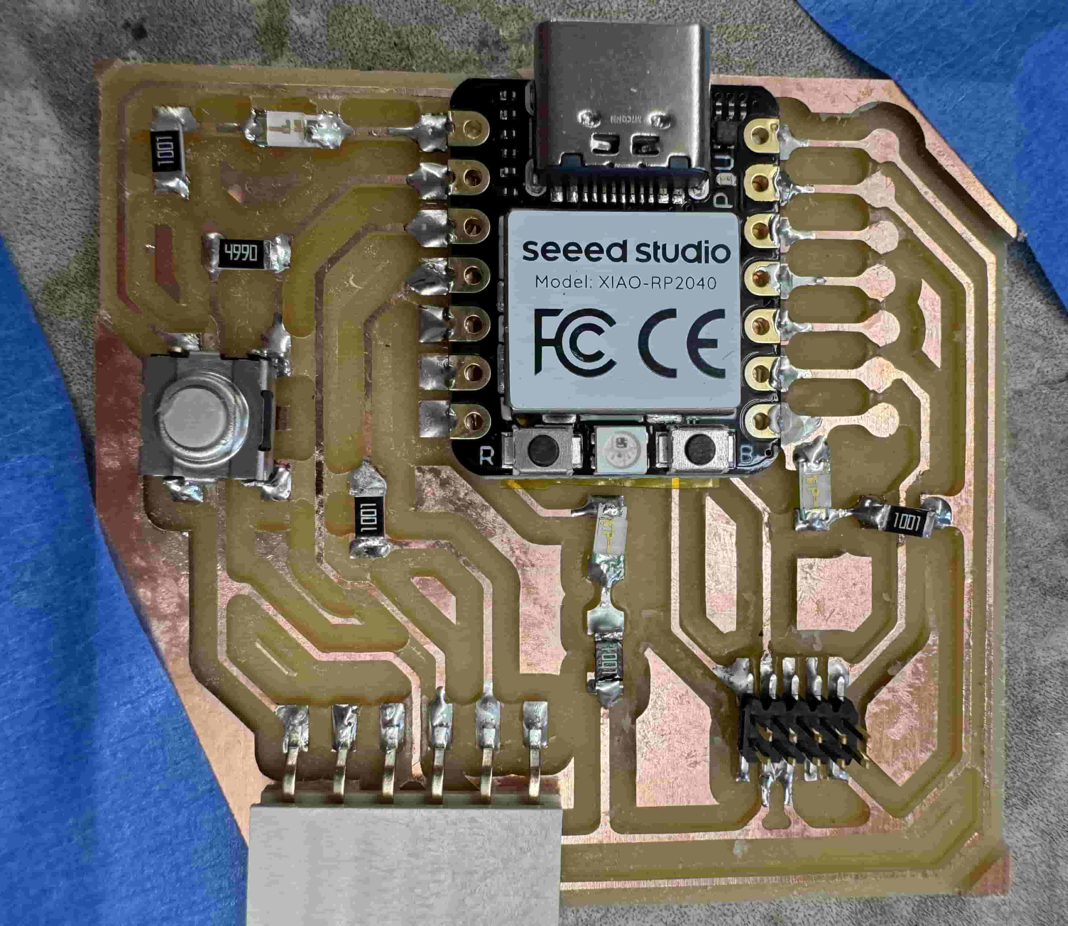
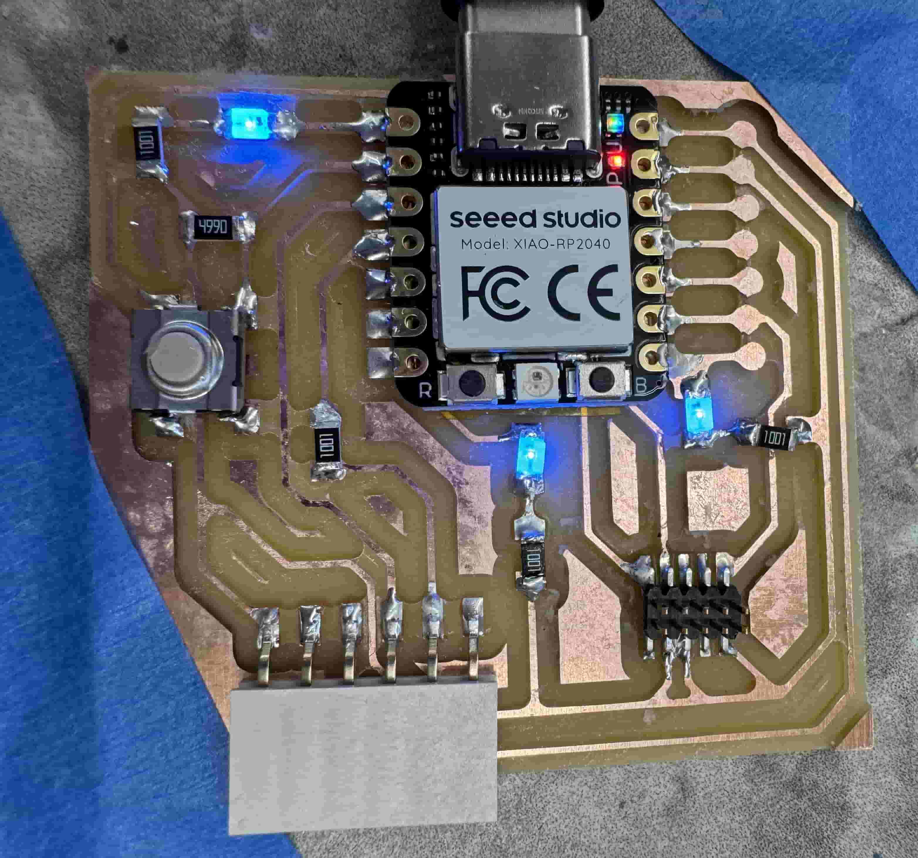
Plugged it in – the LEDs all worked!!
Soldering Problems Encountered:
-
Needed to change soldering iron from 750 degrees fahrenheit to 650 degrees fahrenheit (thankfully realized this before starting)
-
I have shaky hands. To overcome this I taped the PCB board down (carefully so that I didn’t accidentally damage a trace)
-
Reading the fusion microcontroller schematic was difficult, needed a briefing on it (still had trouble visualizing how the pieces were supposed to lay out so I consulted with a friend and her board to help better understand how to relate the schematic to the physical product)
-
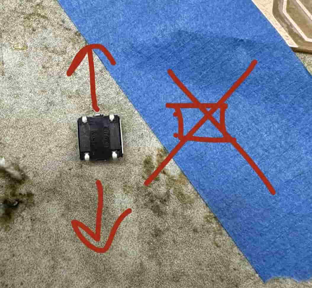
Had to figure out how the button should be oriented
-
Solder bridges and cold solders
-
Holding tiny components was hard, accidentally shot an LED across the room; tried a variety of different electrical tweezers to better grasp and maneuver the pieces
-
Soldering iron I was using at first was old and not working well (a bad soldering iron can be identified if the tip is black/super dark or if, when you try to melt solder stone, it isn’t instant)
-
Orienting myself around the board so that I could access components and trace locations (determined it was easiest to move the stone slab I was soldering on instead of moving myself or moving and re-taping the board)
-
Had to figure out how to use the multimeter to measure continuity and how that would help me figure out which way the LED should lie (I used this pin output image for help as well)
-
Determining which side of the LED was positive and negative (green side is negative; can tell with multimeter: with negative probe on the negative side and positive probe on the positive side, the LED will light up)
-
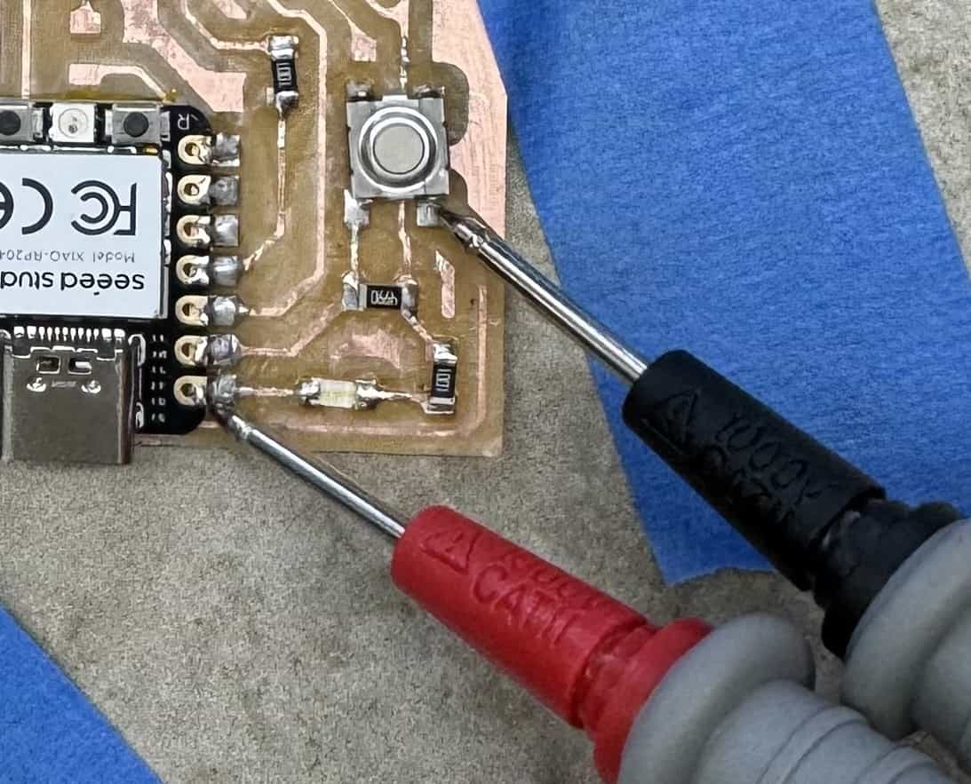
Learning how to troubleshoot; ex. continuity test on multimeter (multimeter will beep to indicate a sturdy connection)
-
The LED connected to pin D0 of the RP2040 was not lighting up. There was a connection between the pin to the end of the trace and the pin to the button… determined that it was a bad LED so pulled it off and replaced it
- Replaced the LED but it still didn’t work, a bad soldering job… pull it off and replace the LED again

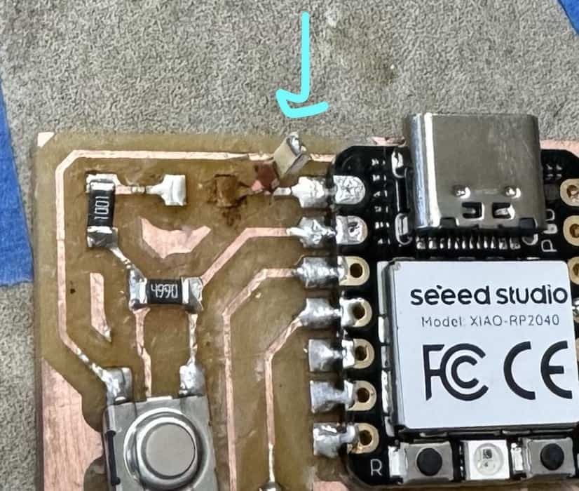
- When taking the LED off the second time, saw black around the trace pad… indicative of a risk for ripping a trace

- Ripped a trace while trying to put the LED back on again (did check that this LED worked with the multimeter before putting it on)
- Misunderstood how to properly fix a ripped trace and broke a trace again (soldered a wire to one side of the LED and the other side of the LED to the remaining pad… wire too stiff and short so that couldn’t maneuver it around to the other trace and ripped off the pad in the process)
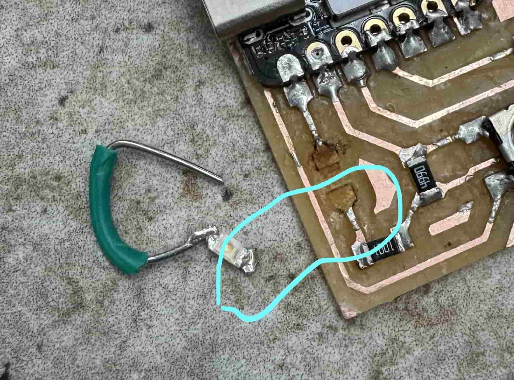
- After properly attempting to fix a ripped trace, continuity test showed a sturdy connection from the pin through the red (power) wire connecting to the LED, but not through the white (ground) wire. My soldering of the white wire missed the pads of the LED so had to re-solder it on

- LED of the ripped trace section was so small and frail that it was not staying soldered to the wires. Used a through-hole LED instead and wrapped the positive wire around the positive lead and the negative wire around the negative lead

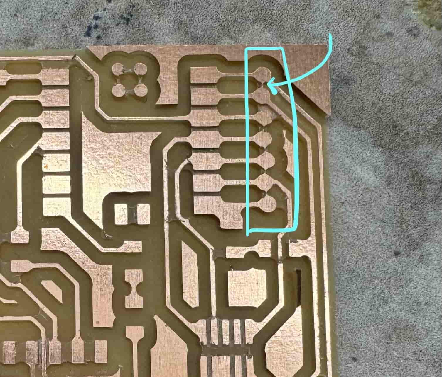
- The circle traces connecting to the RP2040 were not completely milled and were touching a little, preventing the board from working. To fix this, I took a thin pair of electrical tweezers and scraped between the traces.
Programming the Board
Software
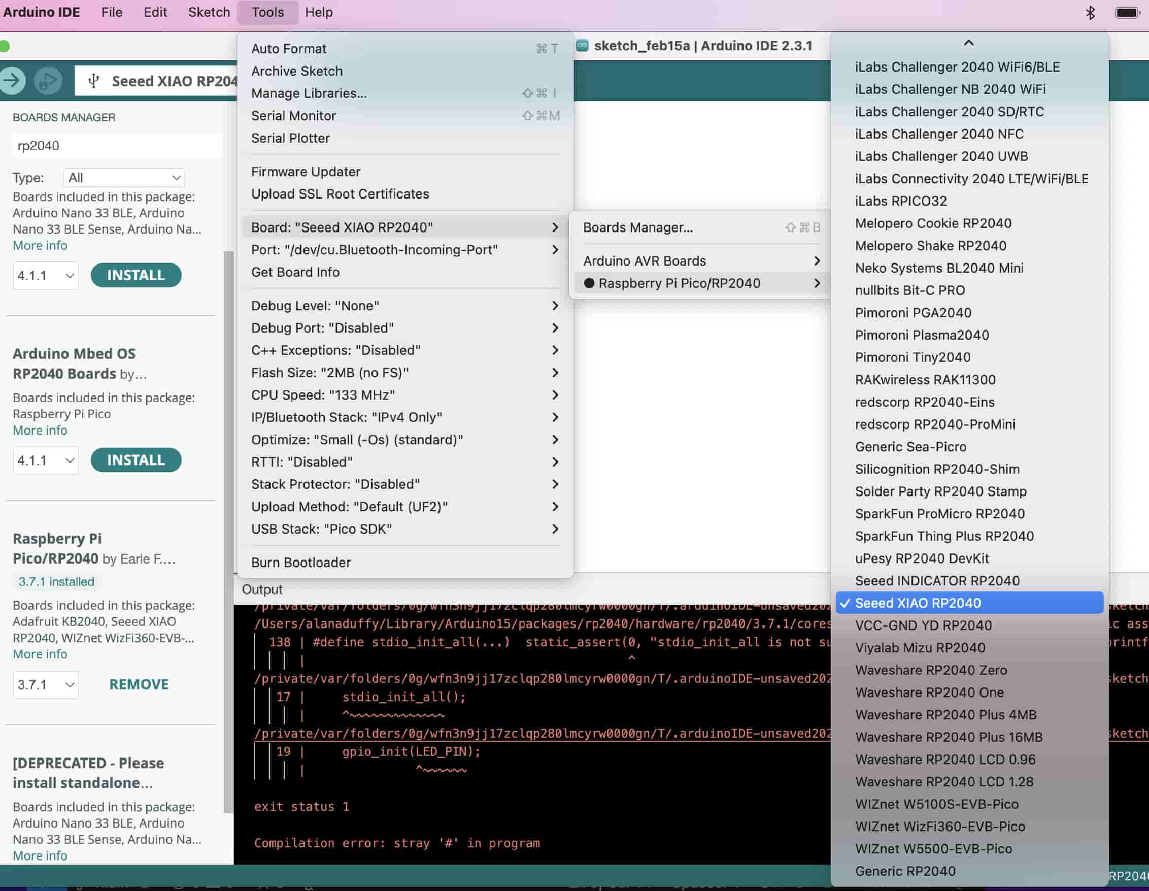
To code the RP2040, I first downloaded Arduino IDE for macOS from this link. I then opened Arduino IDE and clicked on the “Boards Manager” sidebar. I searched and installed “Raspberry Pi Pico/RP2040” by Earle F. Philhower, III. I then changed my board to “Seeed XIAO RP2040” under Tools > Board > Raspberry Pi Pico/RP2040 > Seeed XIAO RP2040.
Then I changed the port to the one my chip was plugged into under Tools > Port (after clicking “Port” I selected “/dev/cu.usbmodem101 Serial Port (USB)” but this will not always work depending on the chip, computer, etc.).
Code
Richard Shan wrote and shared a simple program to test the circuit board by blinking the 3 LEDs. I started by uploading his code to test my board (the LEDs are connected to pins 0, 1, and 26)
Richard’s Code:
  void setup() {

  pinMode(1, OUTPUT); //bottom right LED

  pinMode(26, OUTPUT); //top left LED

  pinMode(0, OUTPUT); //bottom left LED

}


  void loop() {

  digitalWrite(1, HIGH); //turns bottom right LED on

  digitalWrite(26, HIGH); //turns top left LED on

  digitalWrite(0, HIGH); //turns bottom left LED on


  delay(1000); //waits for 1 second


  digitalWrite(1, LOW); //turns bottom right LED off

  digitalWrite(26, LOW); //turns top left LED off

  digitalWrite(0, LOW); //turns bottom left LED off


  delay(1000); //waits for 1 second

}
Next, I uploaded the following code so that the LEDs would light up when the button is pressed, and turn off when the button is not:
void setup() {


  pinMode(1, OUTPUT);

  pinMode(26, OUTPUT);

  pinMode(0, OUTPUT);


  pinMode(27, INPUT_PULLUP);

}


void loop() {

  int buttonState = digitalRead(27);

  if (buttonState == LOW) {

  digitalWrite(1, LOW);

  digitalWrite(26, LOW);

  digitalWrite(0, LOW);

  }

  else {

  digitalWrite(1, HIGH);

  digitalWrite(26, HIGH);

  digitalWrite(0, HIGH);

  }

}
Reflection
This week really showed me to trust the process. So many things went wrong, but in the end it all worked out and it felt so so good when it did. Yes, it was an emotional rollercoaster, but I feel I learned so much through this week and really had to understand what I was doing to succeed.
References
Quentorres. swd+uart adapter+hello board - xiao rp2040
Chloé Laurent Fab Academy 2022
Seeed Studio XIAO RP2040 information and pinout