Final Project
Updated Weekly with Project Progress


On this page you can find details about my final project including the design process, design files, and final product. For more information also see:
- Project Development - including project plan.
- Applications & Implications - answers key questions about project, includes Bill of Materials, Systems Integration, etc..
- Invention, IP & Income - includes dissemination plan..
Problem & Objective
Companies like Meta and Apple bet that our future will be lived in digital worlds. Either entirely digital (VR) or hybrid (AR). I am betting on AR. And while AR products like the Apple Vision Pro are impressive, they mainly projects our existing digital workspace into the real world. It's computer-centered. Not human-centered.
I want to start with the human body, senses, and consciousness and overlay information to enhance our lived experience, rather than pulling us out of it. This means NOT being tied to small screens and keyboards.
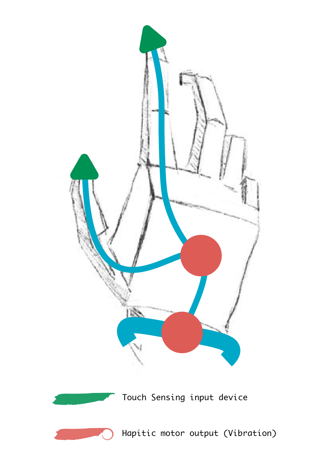
For my project, I'll develop wearable device(s) with both input and output functionality. I'll specifically focus on touch as a sense (to complement existing audio and visual devices). This includes input (touch sensing, computer vision) and output (haptic vibration) functionalities. The device should be capable of pairing with existing or new applications to enhance the user experience while on the go - replacing in whole or in part the need to look at screens, type, or listen.
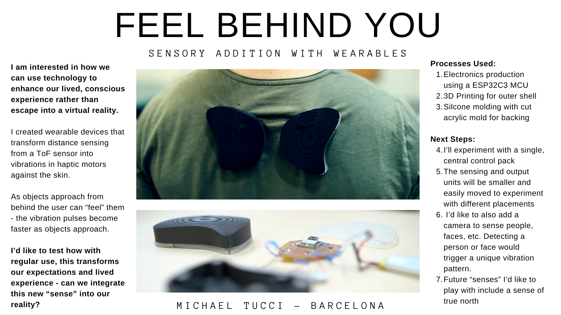
I selected "eyes in the back of the head" as the use case for my project, so that users can "feel" what's behind them. I used a time of flight sensor to sense distance as an input. As objects approach the sensor haptic motors vibrate against the user's skin to alert of objects approaching from behind. As objects get closer the pattern of vibration becomes stronger.
Final Product
Slide
Video
Design Process
Use Cases Considered
The main audience will be app developers, but for practical purposes I'll pick a first use case and design end to end. See potential use cases below
Potential Use Cases:
- SELECTED USE CASE. Eyes in back of head - camera worn on back or back of head transformed to pattern of vibrations on hands / neck / body so user can "sense" what's behind them.
- Google map directions delivered directly to your hands (keeping eyes and ears free).
- Touch typing - use a pre-defined pattern of tapping fingers together to type text (e.g. right hand thumb and index finger tapping together = "a".
- Feel tragedy - this is building on an idea shared by Daniel in our Fab Academy Class in Barcelona - output (sudden vibration, noise, shock) would be received based on external data like death or violence threshold reached (e.g. every X deaths reported), war event, natural disaster, etc).
- Infinite selfie stick - with your phone at a distance tap your fingers to trigger a photo taken.
- Sense of true north - pendant on necklace buzzes lightly every time you're facing north.
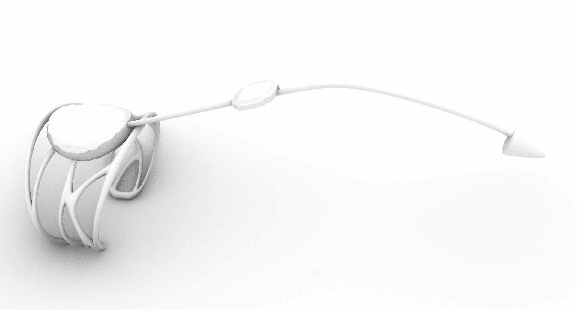
Early 3D Renderings - Possible Wearable Design
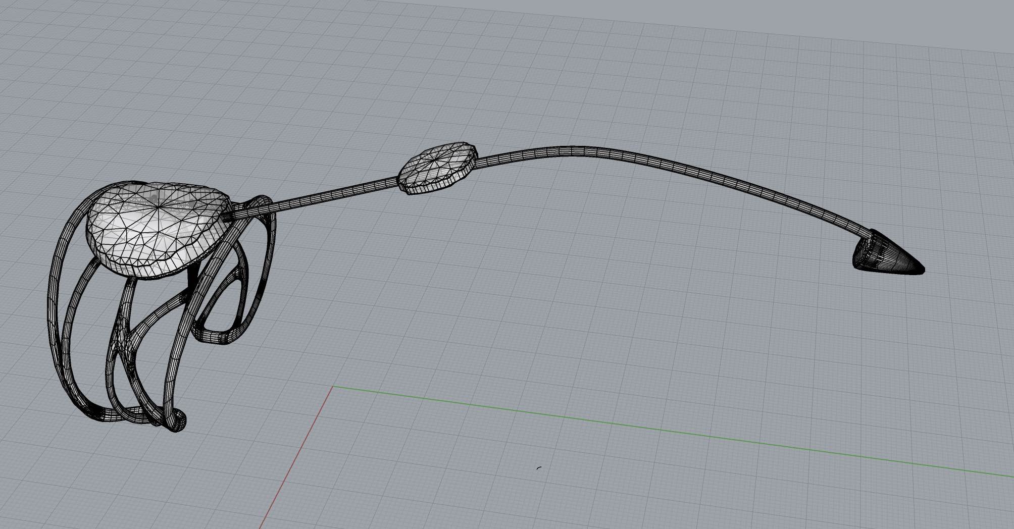
Rough Sketch - First Spiral
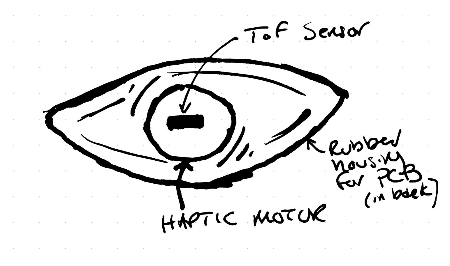
For the initial spiral I focused on producing 2 "eyes" each with a ToF sensor that vibrates with increasing intensity as objects approach it. The vibration is created with a haptic motor. Each will be self contained with its own microcontroller with battery power. My hypothesis was that having the vibration occur at the same point as sensing will allow the body / mind to learn with time that vibration occurs when that area of the body is getting close to an object. You can see more about the initial development in inputs week and outputs week.
Testing TOF Sensor
Testing Haptic Motor
Creating Casing
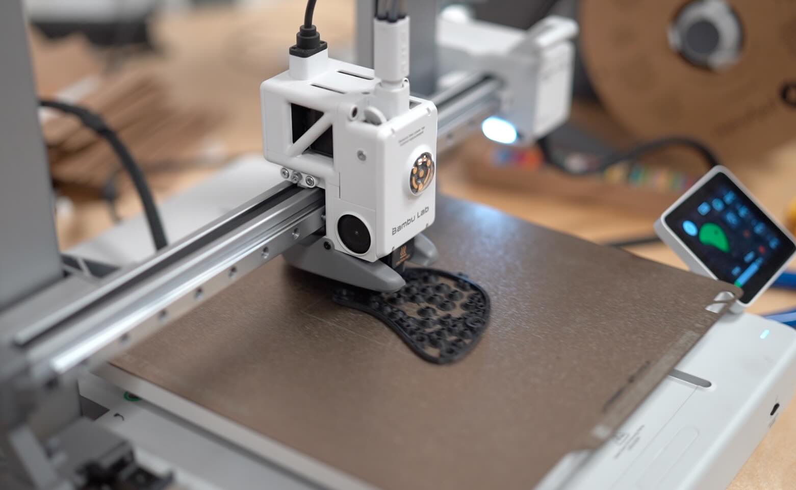
To create the outer casing I used 3D printing and molding and casting with Silicone. The 3D printed outershell holds the electronics while the soft silicone backing adheres to clothing and serves as a non-rigid vessel to encase the haptic motors. The two connect with magnets, also holding the entire apparatus to the user's clothing (via a magnet placed inside the shirt). I decided to do the design in a wing shape, so that when 2 are worn, they look like small wings on the back of the user.
3D Printed Shell
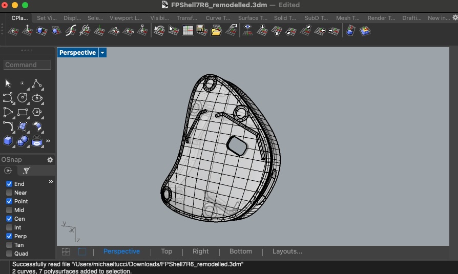
I designed the shell in Rhino and printe with a Preusa XX. I had some trouble getting all the elements to fit together and convert to a mesh, but with some help from the teachers in the lab I got the file ready for print. I converted to STL and printed. The shell included guide walls to house the PCB and a window so that the ToF sensor can have an unobstructed view.
Silicone Backing
For the backing I used Platsil FS-20 - a quick curing silicone. I created the mold by laser cutting acrylic. I then superglued the mold together, including spaces for the haptic motors.

Electronics, Power & Programming
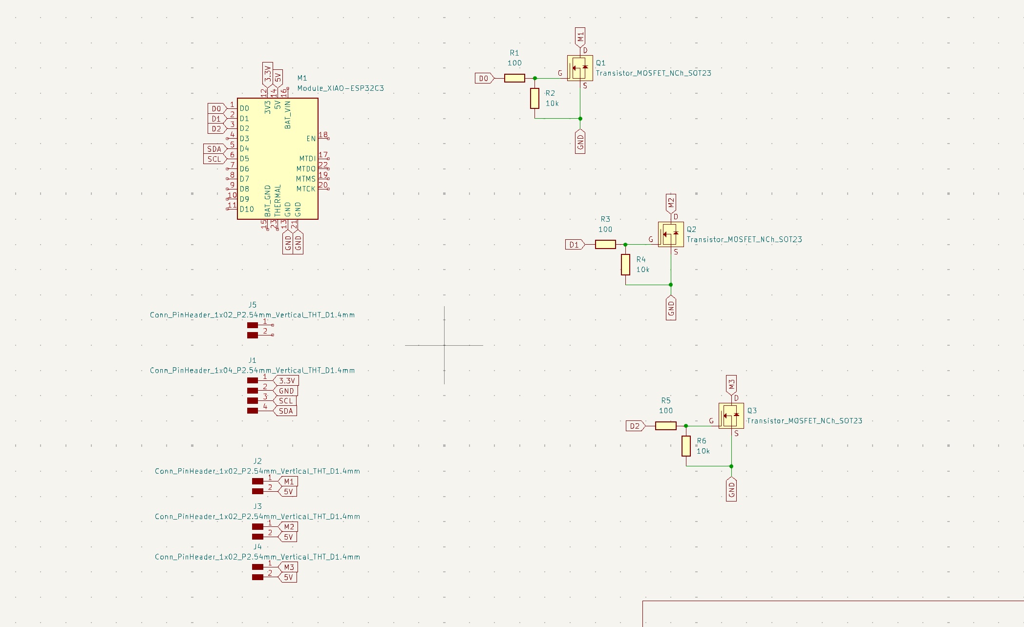
I designed the PCB in Kicad to use the XIAO esp32c3 MCU. The board incorporates 3 haptic motors using MOSFETS to turn them on and off. Each haptic motor was connected to a GPIO pin of the MCU. The ToF sensor was connected to the SDA, SCL, GND, and 3.3V pins. All power was provided by 3.3V line connected to a lithium battery connected via a hole cut in the board as the battery pins are located on the underside of the MCU. The connections for the ToF sensor were likewise made via drill holes as the sensor would be housed on the back of the PCB.
PCB
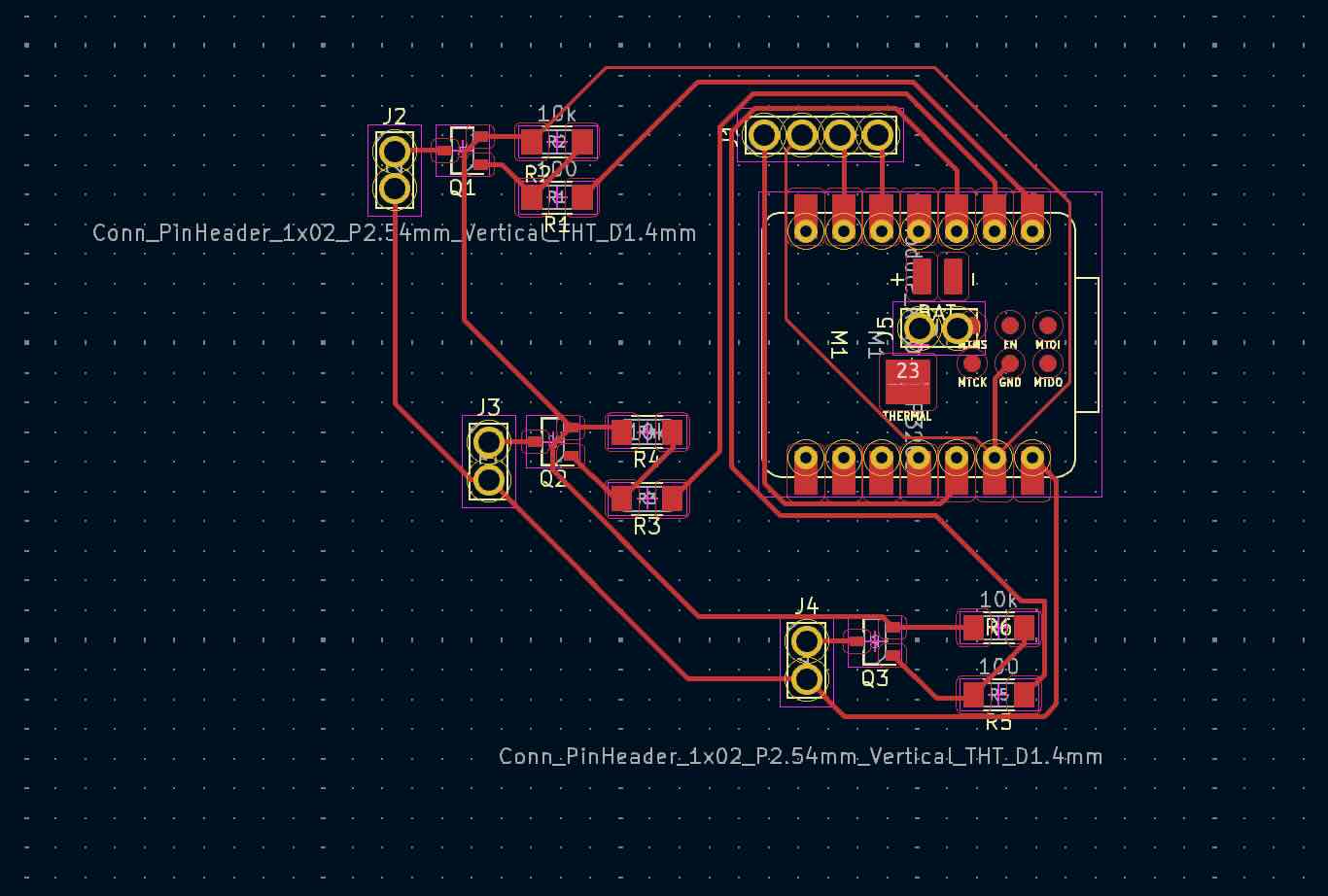
SCHEMATIC
I programmed in Arduino with help of ChatGPT - the code establishes a min distance (300mm) and max distance (2m). It then establishes a delay time to modulate pulsing of the haptic motors. It uses nested if statements to modulate the delay time. If the distance detected by the ToF sensor is less than the min distance, there is no delay (constant vibration). If the distance is between the max and the min distance the delay time is scaled up based on that distance (using map function). If the distance is greater than the max distance there is no vibration whatsoever. I arrived at this code after testing other vibration patterns. This pulsing pattern was the easiest to detect and differentiate distance (e.g. vs just modulating vibration strength where it was hard to detect difference between low and high vibration).
Arduino Code
#include <Wire.h>
#include <VL53L0X.h>

VL53L0X sensor;

// Pin definitions
const int hapticMotorPin1 = 2; // GPIO2, D0
const int hapticMotorPin2 = 3; // GPIO3, D1
const int hapticMotorPin3 = 4; // GPIO4, D2

// Thresholds (in millimeters)
const int minDistance = 300;    // 0.3 meter
const int maxDistance = 2000;   // 2 meters

void setup() {
  Serial.begin(9600);
  Wire.begin();

  sensor.init();
  sensor.setTimeout(500);
  sensor.startContinuous();

  pinMode(hapticMotorPin1, OUTPUT); // Set the first haptic motor pin as output
  pinMode(hapticMotorPin2, OUTPUT); // Set the second haptic motor pin as output
  pinMode(hapticMotorPin3, OUTPUT); // Set the third haptic motor pin as output
}

void loop() {
  int distance = sensor.readRangeContinuousMillimeters();
  float distanceMeters = distance / 1000.0; // Convert distance to meters

  Serial.print("Distance: ");
  Serial.print(distance);
  Serial.print(" mm (");
  Serial.print(distanceMeters);
  Serial.println(" meters)");

  if (sensor.timeoutOccurred()) {
    Serial.println(" TIMEOUT");
  } else {
    if (distance <= maxDistance) {
      // Calculate delay based on distance
      int delayTime;
      if (distance <= minDistance) {
        delayTime = 0; // No delay, constant vibration
      } else {
        delayTime = map(distance, minDistance, maxDistance, 0, 1000); // Map distance to delay time
      }

      if (delayTime == 0) {
        // Constant vibration
        analogWrite(hapticMotorPin1, 255);
        analogWrite(hapticMotorPin2, 255);
        analogWrite(hapticMotorPin3, 255);
      } else {
        // Pulsed vibration
        analogWrite(hapticMotorPin1, 255);
        analogWrite(hapticMotorPin2, 255);
        analogWrite(hapticMotorPin3, 255);
        delay(100); // Vibration on time
        analogWrite(hapticMotorPin1, 0);
        analogWrite(hapticMotorPin2, 0);
        analogWrite(hapticMotorPin3, 0);
        delay(delayTime); // Vibration off time
      }
    } else {
      // No vibration if distance is greater than maxDistance
      analogWrite(hapticMotorPin1, 0);
      analogWrite(hapticMotorPin2, 0);
      analogWrite(hapticMotorPin3, 0);
    }
  }

  delay(100);
}
Bill of Materials
| Component | Info / Model Number | Quantity | Supplier | Product Code | Unit Price | Total Price |
|---|---|---|---|---|---|---|
| ToF board | VL53L0X | 2 | Adafruit | 3317 | $14.95 | $29.90 |
| Esp32c3 MCU | ESP32-C3 | 2 | Seeed | 113991054 | $4.99 | $9.98 |
| Haptic Motors | 1597-1244-ND | 6 | Seeed / Digikey | 316040001 | $1.46 | $8.76 |
| Mosfets | 2N7002L | 6 | Digikey | 2N7002L | $0.08 | $0.48 |
| 10k Ohm Resistors | RC0603FR-131KL | 6 | Digikey | RC0603FR-131KL | $0.02 | $0.12 |
| 100 Ohm Resistors | RC0603FR-7W100RL | 6 | Digikey | RC0603FR-7W100RL | $0.01 | $0.06 |
| 4mm Magnets | S-04-01-N | 20 | Supermagnete | 7640155437011 | $0.28 | $5.60 |
| 3D printed & molded silicone housing | NA | 2 | Provided by Fab Lab | NA | $2.50 (est) | $5.00 (est) |
| PCB Board | NA | 2 | Provided by Fab Lab | NA | $0.25 (est) | $0.50 (est) |
| Total Cost | $60.40 | |||||