10. Mechanical design
The group assignement can be found here.
Extrusion, the head (Pol-Emile)
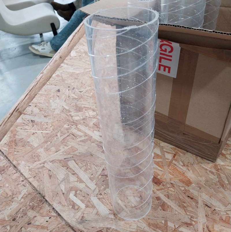
To make the head we were inspired by the work of bryancera and Adel Kheniche. We have at our disposal a PMMA tube 900mm in diameter, 3mm thick and 400mm high, as well as an 8mm rod and a nut compatible with it.
We had to model the various parts. For this part, they were modelled using FreeCad. The parts are :
- The nozzle
- The piston
- The motor gear
- The gear on the screw
- The motor support
- The connection between the tube and the screw gear
All these parts were printed in PLA using 3D printers. In a future version, we plan to use nylon for the gears to improve their mechanical strength.
The nozzle
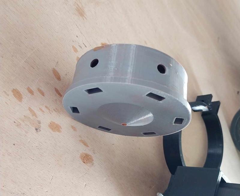
For the nozzle, the main challenge was to make a part that could be connected to the tube without letting any material through, and that was interchangeable. To hold it in place, a system of bolts has been inserted into the PLA, and the screws start on the outside and are inserted inside. The inside has a concave shape to facilitate the flow of the material and the hole releasing the material is also funnelled for the same reasons.
The piston
The purpose of the piston is to push the material and transmit the force given to it by the rod. It is convex in shape to distribute the forces as evenly as possible. To make it more resistant, we filled it with more material (30%) and defined it finely. Two O-rings have been placed on the edges to prevent the material from passing behind the piston.
Gears
In order to have sufficient force, the documentation we used indicated that the ideal ratio was between 1:20 and 1:30. Initially we used a ratio of 1:20, which gave us a tiny gear on the motor and a huge one on the rod. However, it turned out that the gears weren’t actually big enough to cover the distance between the centre of the motor and the centre of the tube, so we switched to a 1:22 ratio.
To attach the gears we have two systems: on the motor a system of nuts inside the PLA and screws that press on the motor shaft. And for the screw gear, a fixing with the nut matched to the shaft.
The motor support
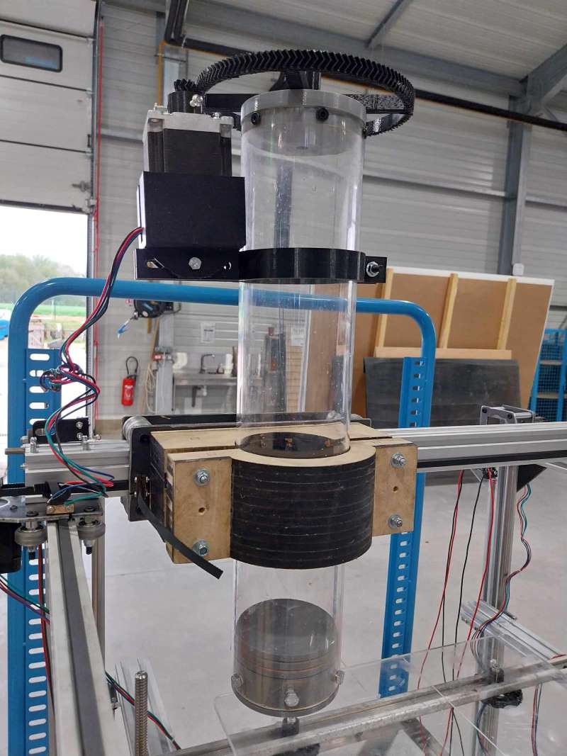
The main problem here is that it’s quite complex to know the precise position of the motor, because it depends on the precision with which the gears will be printed. To overcome this problem, we’ve created an adjustable position using a screw. The motor is held to the tube with a clamp.
The connection between the tube and the screw gear
This part is the most complex, because this is where we have to play with the degrees of freedom to constrain the parts as we wish. We want the screw to exert downward pressure, so we want it to translate rather than rotate. We therefore need to block it in every other direction. To counteract the pressure pushing back the motor and the screw, the screw gear is embedded in the coupling. The screw and nut are integral.
Next improvements
Several improvements can be made to the head:
- Add a thoric seal to the piston
- Make a system for embedding the rod in the piston
- Make a system to force the two gears to remain in contact (work on degrees of freedom)
- Improve motor support
Files
Here you can find the STL nozzle, piston, top, motor, engineMount1, engineMount2, gear


