6. Embeded programming
Assigement:
- write a program for a microcontroller development board that you made,to interact (with local input &/or output devices)and communicate (with remote wired or wireless devices)
- browse through the data sheet for your microcontroller
- compare the performance and development workflows for other architectures
We have attend a course with Luc HANNEUSE this week to help us with the coding section.
At the begining, we have done the group assignement here. My part is the RA4M1 from Renesas.
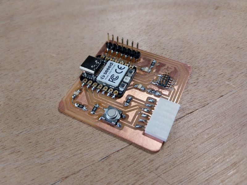
Hero shot
First attempt
In the previous week I made my board flash in one of the LEDs. I decide to do the same thing with all the LEDs, using the same code and just changing the pin value.
Then I decide to make it a bit more complex by alternating the light.
void setup() {
  pinMode(0, OUTPUT);
  pinMode(1, OUTPUT);
  pinMode(26, OUTPUT);
}

void loop() {
  digitalWrite(0, HIGH);
  digitalWrite(26, LOW);
  delay(1000);
  digitalWrite(0, LOW);
  digitalWrite(1, HIGH);
  delay(1000);
  digitalWrite(1, LOW);
  digitalWrite(26, HIGH);
  delay(1000);
}
Fading
To continue, I’m trying to vary the intensity of the light. I can’t vary the voltage, but what I can change is the pulse, which is what we call PWM. In the RP2040 data sheet, it’s on page 363. This allows me to find out the maximum value of the pulse. Finally, I use the initial fade programme:
#define ledPin 1

void setup() {
}

void loop() {
  for (int fadeValue = 0; fadeValue <= 255; fadeValue += 5) {
    analogWrite(ledPin, fadeValue);
    delay(30);
  }

  for (int fadeValue = 255; fadeValue >= 0; fadeValue -= 5) {
    analogWrite(ledPin, fadeValue);
    delay(30);
  }
}
It works well, but I’d like to know if I can do it myself and what the effects will be. At first I just used the Delay and a simple loop. But the Delay was too slow, so I need to use delayMicroseconds(). So I do this code:
#define ledPin 26
int compte = 0;
int loopp = 10000;

void setup() {
  pinMode(ledPin, OUTPUT);
}

void loop() {
  while(compte < 10000)
  {
    digitalWrite(ledPin, HIGH);
    delayMicroseconds(loopp - compte);
    digitalWrite(ledPin, LOW);
    delayMicroseconds(compte);

    compte +=100;
  }
  while(compte > 0)
  {
    digitalWrite(ledPin, HIGH);
    delayMicroseconds(loopp - compte);
    digitalWrite(ledPin, LOW);
    delayMicroseconds(compte);

    compte -=100;
  }
}
In the end, the result was pretty much the same, so let’s move on to the inputs.
Button
My aim here was to light the LEDs one at a time each time the button was pressed. I used the button template in arduino as a template. Here’s the code:
#define buttonPin 27
#define led1 1
#define led2 26
#define led3 0

int compte = 0;
int buttonState = 0;
int buffer = 0;

void setup() {

  pinMode(led1, OUTPUT);
  pinMode(led2, OUTPUT);
  pinMode(led3, OUTPUT);

  pinMode(buttonPin, INPUT);
}

void loop() {
  buttonState = digitalRead(buttonPin); //see the state of the button
  Serial.println(compte);

  if(buttonState == 1) // if the button is engage
    buffer = 1;
  if(buttonState == 0 && buffer == 1){ //if we relese the button (we increment only here)
    compte ++;
    buffer = 0;
  }

  if(compte >2) //switch between the 3 LEDs
    compte=0;

  if(compte == 0){ //Turn on and off each LED
    digitalWrite(led1, HIGH);
    digitalWrite(led3, LOW);
  }
  else if(compte == 1){
    digitalWrite(led2, HIGH);
    digitalWrite(led1, LOW);
  }
  else{
    digitalWrite(led3, HIGH);
    digitalWrite(led2, LOW);
  }
}
The result is quite convincing. At first, I don’t take into account the fact that the variable will change as long as the button is pressed, so I have to add a buffer to see when the button is released so that I can increment.
Send information
In this part, I wanted to send information over the wire to turn a desired LED on and off. First I use the “ReadASCIIString” model. The data is read from the serial monitor (in the tools section). First I have to configure my communication channel, then I send the data I want to see.
#define led1 1
#define led2 26
#define led3 0

int varr = 0;

void setup() {
  Serial.begin(9600);

  pinMode(led1, OUTPUT);
  pinMode(led2, OUTPUT);
  pinMode(led3, OUTPUT);
}

void loop() {
  if(Serial.available() > 0) {
    varr = Serial.read();

    if(varr == 49){
      digitalWrite(led1, 1);
      digitalWrite(led2, 0);
      digitalWrite(led3, 0);
      Serial.println("here");
    }
    if(varr == 50){
      digitalWrite(led1, 0);
      digitalWrite(led2, 1);
      digitalWrite(led3, 0);
    }
    if(varr == 51){
      digitalWrite(led1, 0);
      digitalWrite(led2, 0);
      digitalWrite(led3, 1);
    }
  }
}
One of the main problems with this code is that the “varr” variable is in ASCII, so I have to take that into account. I find that when I read the console it shows 4910, 5010 and 5110. At first I put 4910, but that had no effect, then I realise they all have 10 at the end, so I delete it and it works.
Other IDE
For the previous test, I used the Arduino IDE, so for a change, I’m trying the Visual Studio Code IDE. First of all, I install the PlatformIO IDE but I can’t get it to work. I also test the arduino IDE for VS code, but I can’t get it to work either. I’ll continue with VS code later.
Connecting a motor
To connect a micro servo 9g, I need to update my card with a pin like this one:
This will allow me to be directly connected to the right pin of the RP2050. Next, I need to import the servo library so I can use it by adding this to the beginning of my code:
#include <Servo.h>
Then I connect the servo to the right pins, following the quentor guide. I want the servo to turn slowly and constantly. But my servo only rotates from 0 to 180 degrees, so I need to manage that amplitude. I’ve written this code:
#include <Servo.h>

Servo myservo;
int angle = 0;

void setup()
{
 myservo.attach(2); // initialise the pin number
}
void loop()
{
  myservo.write(angle); // set position
  delay(50);
  angle++;
  Serial.println(myservo.read()); //read position
  if(angle>179) //set a loop
    angle = 0;
}
I deliberately reduce the speed by adding a delay, and reset the position each time the servo reaches 180 degrees.
Reading temperature and humidity
For my final project, I’m going to need to read the temperature, so I’m trying to do it with a DTH11. I connect the right pins following the doc, then I ask ChatGPT to do some code for me. Here’s the modified version:
#include "DHT.h"

#define DHTPIN 2    // define the pin
#define DHTTYPE DHT11 //define the sensor I'm using

DHT dht(DHTPIN, DHTTYPE);

void setup() {
  Serial.begin(9600); //send information
  dht.begin();
}

void loop() {
  delay(2000);

  float humidity = dht.readHumidity();
  float temperature = dht.readTemperature();

  Serial.print("Humidity : ");
  Serial.print(humidity);
  Serial.print(" %\t");
  Serial.print("Temperature : ");
  Serial.print(temperature);
  Serial.println(" degree celcius");
}
As with the servo, I need to add a library, and I install DHT Sensor Library. The system works, and the sensor gives a consistent indication: 22.1 degrees in an indoor room.
Files
Here you can find the arduino button file
Here you can find the arduino fading file
Here you can find the arduino read file
Here you can find the arduino servo file
Here you can find the arduino temparature and humidity file