Networking and Communications
Individual Assignment
This week we are tasked with designing, building, and connecting wired or wireless node(s) with network or bus addresses.
Group Assignment
Our group task this week is to send a message between two projects. Link to our PAST Innovation Lab Group Page.
For the group assignment this week, we did a lot of internet searches to find a setup and code that we found to be easily understandable, and that we had the resources and time for.
After a lot of reading among help forums and similar sites, I noticed that a lot of people cannot seem to get the XIAO RP2040 I2C communication protocol to run on their microcontroller PCB's. I saw one success, from Jesal Mehta (a Fab Academy student), where they had communicated from a XIAO RP2040 and an Arduino Uno board. We tried this setup, and code and it failed.. So we tried to modify in ways we knew how and still, no success so we moved on.
This first attempt we connected the SCL of the XIAO RP2040 to the SDA of the Arduino UNO and vice versa to make the two connections for communication. We also connected GND to GND. Each device has its own computer and its own code. I am opting to not include the code on this page because I do not want to steer anyone in the wrong direction, so please refer to the previous link if you wish to learn more about this trial.
We were using an Arduino Uno R4, which has a built in LED matrix display, so we changed a bit of the code to try to get that to work in replacment of the external LED they used in the link's example... Ultimately, we knew the connection was right in some way (as you can see from the video) but it was not 100% correct. The serial monitor for the "master" was not displaying anything and the Arduino Uno R4 serial monitor was being a bit wonky... I thought it would display the bytes as it received them but we couldn't really tell what was going on and were not learning anything. So we called that a good first try and moved on.
We kept searching for examples to help us and researching how these connections and codes worked and I finally found another student who had success using just two Arduino Uno clone boards and a wired . This was Jason Goodman from Fab Lab Wheaton, he used the same code for both devices on two different computers. It was a simple wired serial communication protocol. This seemed doable!
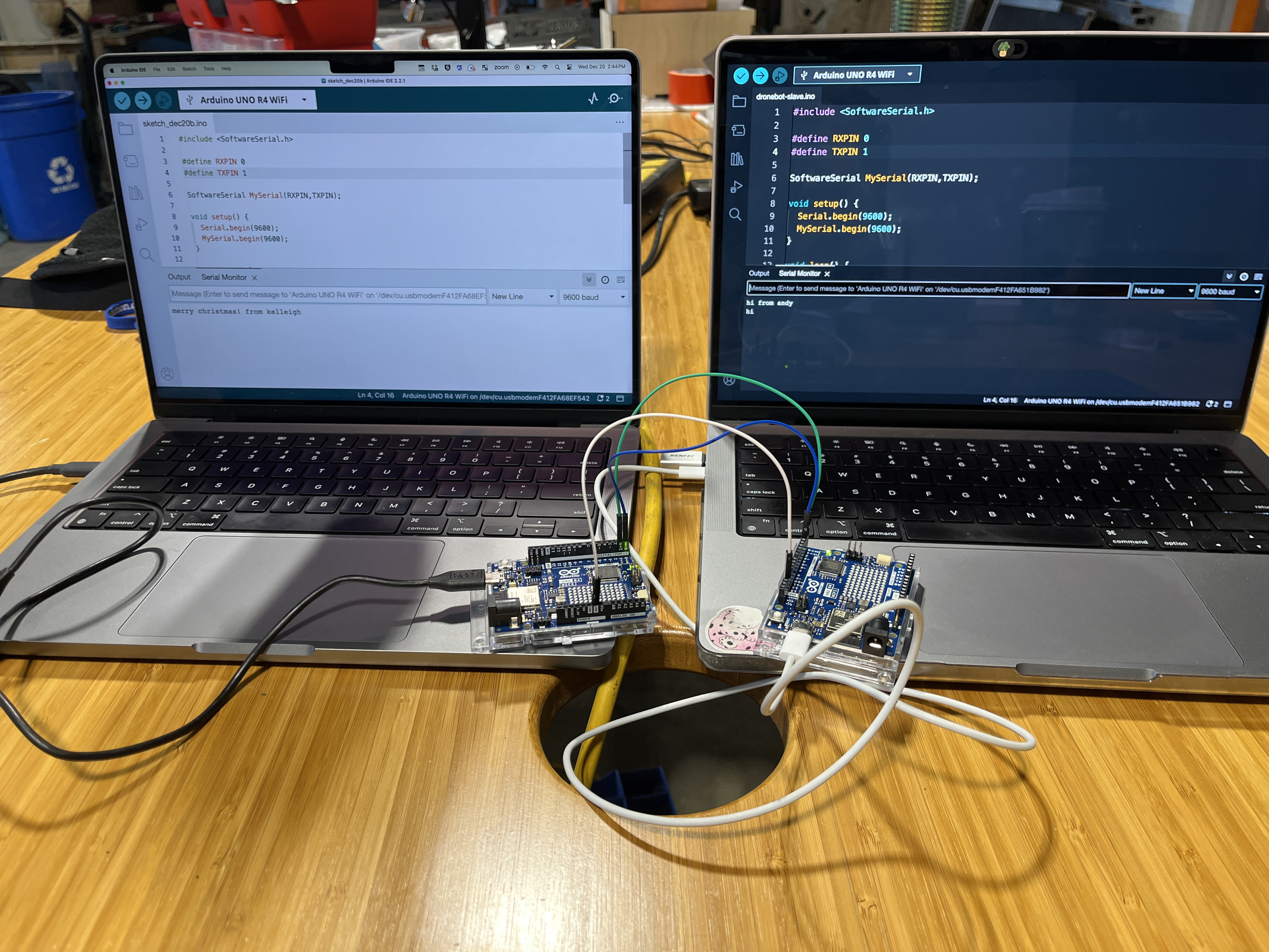
We will be using two Arduino Uno R4's.
Connections:Connect the TX of Arduino A to the RX of Arduino B. Connect the RX of Arduino A to the TX of Arduino B. Connect GND of A to the GND of B. Plug each Arduino into its own computer.
Code: The code used for Arduino A and B is the same. On Jason's page, he explains that he wrote the code to set up a hardware and a software serial link, copy bytes read from software to hardware, and vice versa. His page is very helpful and pretty easy to follow, even for beginners.
#include <SoftwareSerial.h<

         #define RXPIN 0
         #define TXPIN 1

         SoftwareSerial MySerial(RXPIN,TXPIN);

         void setup() {
           Serial.begin(9600);
           MySerial.begin(9600);
         }

         void loop() {
           int incomingByte = 0;
           if (Serial.available() > 0) {
             incomingByte = Serial.read();
             MySerial.write(incomingByte);
           }
           if (MySerial.available() > 0) {
             incomingByte = MySerial.read();
             Serial.write(incomingByte);
           }
           delay(5);
         }
The code allows for the serial monitor of computer A to print the message sent by computer B through Arduino B and Arduino A. You can see the on board TX LED light up when it receives a message from the other board.
When we had the first successful message sent and received, we were so excited because we hadn't had many successes today. In the photos and videos below you can see the connections we made, and the messages being sent and received!
Other Useful Sources
- Robot Electronics - Using the I2C Bus
- Medium - Microcontroller Connection Protocols: W1, I2C, SPI, UART
- Adrian Torres - Week 13 page
- IT k Funde Youtube - Networking Basics
- SparkFun - Serial Communication
- Kevin McAleer - DO THIS to connect two Picos together - to Pico Communication via UART
- Rohde-Schwartz.com - Understanding UART
Individual Assignment
Serial Bus
This week, I am following Adrian's page on networking and communication (see link above). I am admittingly not the best at programming and well, electronics in general. Adrian's page has taught me a lot and I recommend using it for help if you ever need a tip or hint.
Another group member, Andy, had finally gotten a successful mill of the two node boards and bridge that is necessary to complete the serial communication. See his Networking and Communications Page Here. This is a wired connection consisting of two cables, TX (transmitter) and RX (receiver). In Adrians page, he points out that with the use of a *Bridge* (I will not be using the terminology "Master") you do not need to cross the TX and the RX like you would in other cases.
One serial bus, two serial devices.
NOTE: we ended up changing what we wanted to try to do this week. We changed paths to UART using two Pico boards later on in this page*
Files
Bridge DXF Node DXFUART
The XIAO RP2040 has an RX and TX pin on its datasheet which had me thinking I may be able to communicate between two boards, both having a XIAO RP2040 attached. But I have really very little knowledge on this subject so I will try after I have some success following some tutorials and reading more about it.
Scratch everything I've said so far....
Wired UART using Thonny
My colleague and I have both struggle with this assignment for a long time, so we changed our path and I am going to try to follow along a tutorial that has given someone else a successful outcome, in hopes that I have the same results. Once I have understood what is going on in the process, and if I have enough time, I would like to try to change and edit the code to make my own mini communication project.
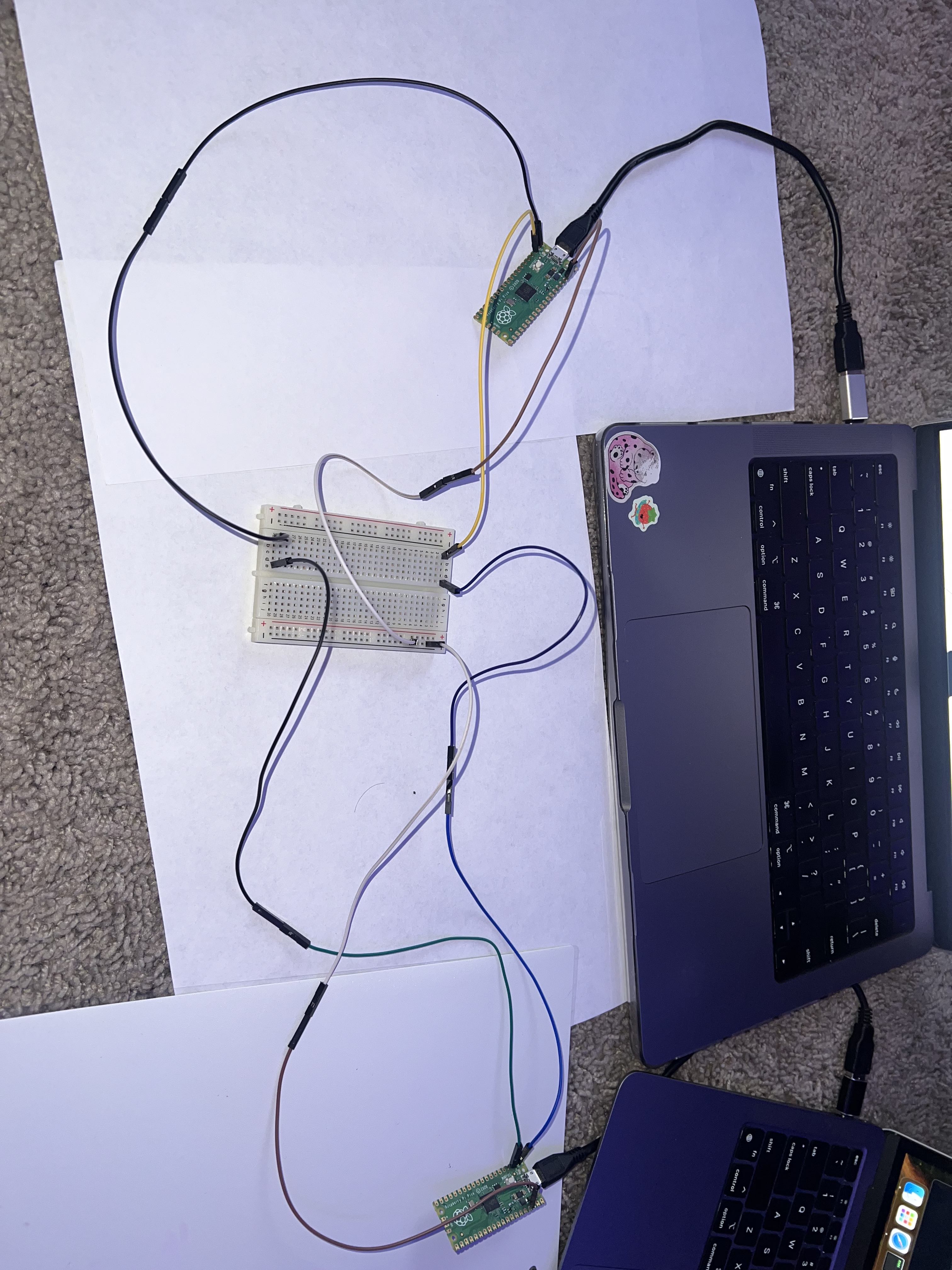
This attempt I will be using two Raspberry Pi Pico's. Shoutout to Ginny from Charlotte Latin for her documentation on her page. I am using that, along with this video from Kevin McAleer on Youtube. I love watching youtube videos when I need help understanding a topic. I am a visual learner and like to see what is going on as the verbal explanation comes across.
To begin, I gathered my two Pico's, their USB power cords, a breadboard, and some wires. I will also need a second computer for this, one to program Pico A, and one to program Pico B.
First, I downloaded Thonny. It is a Python IDE that apparently is recommended for beginners, like me! Both computers must have this. For the first example in the video, I will simply be using the IDE to see the communication between the two boards, and in the second example later on, I will be using an LED light board that my colleague made this week, that will light up when the two boards are communicating with each other.
To continue the first example, I will use two sketches (easy_comms.py and pico_comms_a)on computer A with Pico A, and one sketch on computer B (pico_comms_b).
To wire the boards and make the connection, I use a breadboard and some male-male wires. The connections are as follows:
- TX (Pico A) > RX (Pico B) through the breadboard.
- RX (Pico A) > TX (Pico B) through the breadboard.
- GND (Pico A) > GND (Pico B) through the breadboard.
On computer A, I load in the codes for the easy_comms and pico_comms_a as follows:
easy_comms:
#Easy comms is a simple class that allows you to send and receive messages over a serial port.

    from machine import UART, Pin
    from time import time_ns

    class easy_comms:

        uart_id = 0
        baud_rate = 9600
        timeout = 1000 # milliseconds

        def __init__(self, uart_id:int, baud_rate:int=None):
            self.uart_id = uart_id
            if baud_rate: self.baud_rate = baud_rate

            # set the baud rate
            self.uart = UART(self.uart_id,self.baud_rate)

            # Initialise the UART serial port
            self.uart.init()

        def send(self, message:str):
            print(f'sending message: {message}')
            message = message + '\n'
            self.uart.write(bytes(message,'utf-8'))

        def start(self):
            message = "ahoy\n"
            print(message)
            self.send(message)

        def read(self)->str:
            start_time = time_ns()
            current_time = start_time
            new_line = False
            message = ""
            while (not new_line) or (current_time <= (start_time + self.timeout)):
                if (self.uart.any() > 0):
                    message = message + self.uart.read().decode('utf-8')
                    if '\n' in message:
                        new_line = True
                        message = message.strip('\n')
                        # print(f'received message: {message}')
                        return message
            else:
                return None
pico_comms_a:
# Pico_comms_a
    # Sends commands and listens to responses from pico_comms_b

    from easy_comms import easy_comms
    from time import sleep

    com1 = easy_comms(uart_id=0, baud_rate=9600)
    com1.start()

    while True:
    message = ""
    message = com1.read()

    if message is not None:
    print(f"message received: {message.strip('\n')}")
    sleep(1)
In pico_comms_a I am referencing and pulling information from the easy_comms. I made sure the data was going to the correct port by clicking on the icon in the bottom right corner of the window. Then I hit the green run/go button that runs the program for Pico A.
On computer B, I run pico_comms_b the same way as for Pico A.
    # Pico_comms_b
    # Sends commands and listens to responses from pico_comms_a

    from easy_comms import easy_comms
    from time import sleep

    com1 = easy_comms(uart_id=0, baud_rate=9600)
    com1.start()

    count = 0
    while True:
        # send a message
        com1.send(f'hello, {count}')

        #check for messages
        message = com1.read()

        if message is not None:
            print(f"message received: {message.strip('\n')}")
        sleep(1)
        count +=1
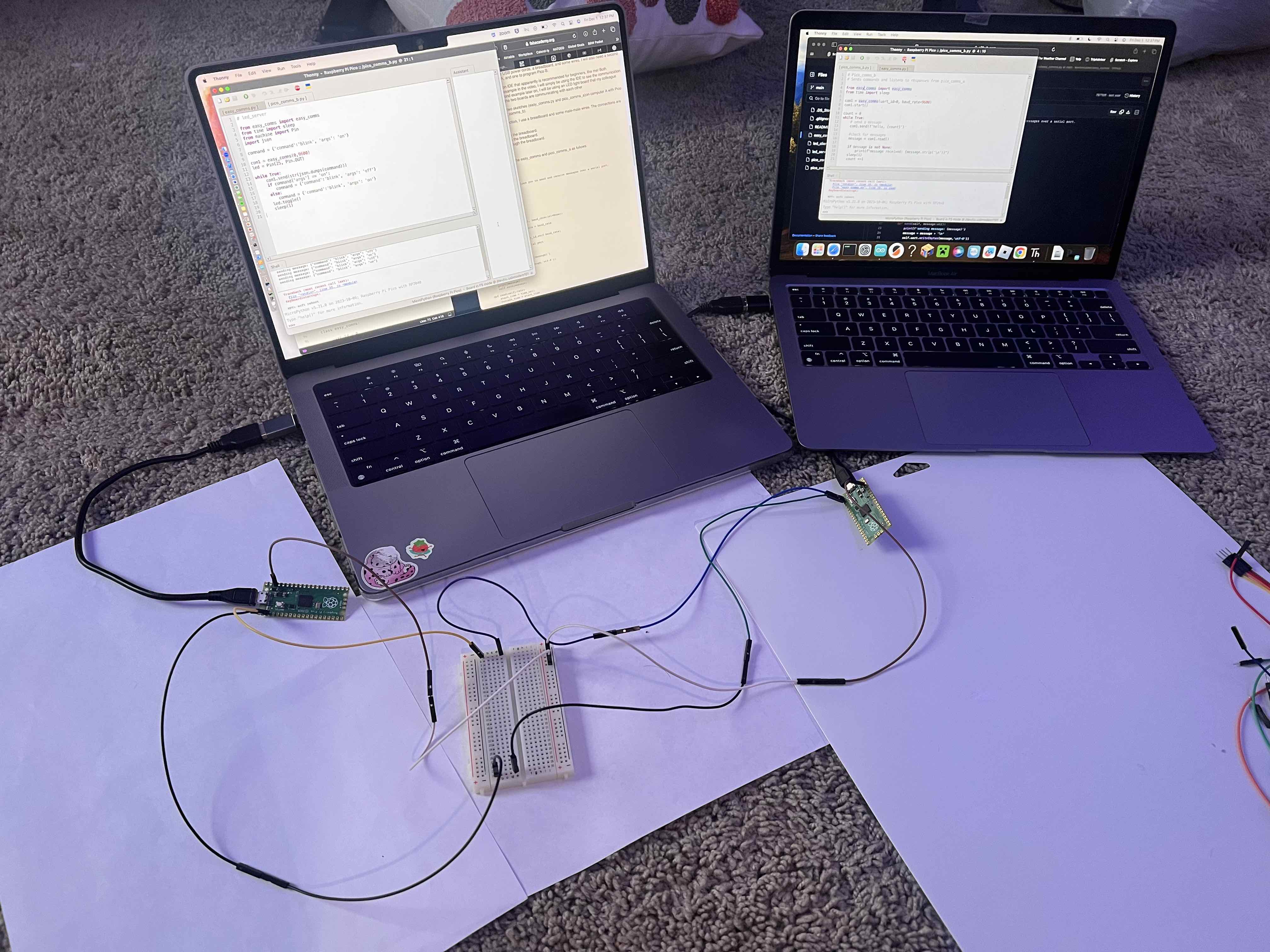
Once both programs are running, the Picos are communicating and you can see the outgoing and incoming messages on the computers.
LED board
To try the second example, using the LED light board made by Andy, I use the same two computers and wire the Picos and LED board together.
- TX (pico A) > RX (pico B) through board.
- RX (pico A) > TX (pico B) through the board.
- GND > GND through board.
On computer A, I code the LED server (pico A) with:
    # led_server

    from easy_comms import easy_comms
    from time import sleep
    from machine import Pin
    import json

    command = {'command':'blink', 'args': 'on'}

    com1 = easy_comms(0,9600)
    led = Pin(25, Pin.OUT)

    while True:
        com1.send(str(json.dumps(command)))
        if command['args'] == 'on':
           command = {'command':'blink', 'args': 'off'}
        else:
           command = {'command':'blink', 'args': 'on'}
        led.toggle()
        sleep(1)
I code Pico B (LED client) with:
  # led_client

    from easy_comms import Easy_comms
    from time import sleep
    from machine import Pin
    import json

    com1 = Easy_comms(0,9600)
    led = Pin("LED", Pin.OUT, value=0)

    while True:
        message = com1.read()
        if message is not None:
            print(f'message: {message}')
            try:
                command = json.loads(message)
                print(f'json: {command}')
                if command['command'] == 'blink':
                    if command['args'] == 'on':
                        led.on()
                    if command['args'] == 'off':
                        led.off()
                sleep(0.1)
            except Exception as e:
                print(f'error: {e}')
When the message is sent between, the LED flashes.