     individual assignment:
      design, build, and connect wired or wireless node(s)
      with network or bus addresses
   group assignment:
      send a message between two projects
Group Work
I was unable to write up this week's group assignment with my group, so I redid it on my own and am writing up my results here. The group assignment is to "send a message between two projects". The simplest way to do this is using software serial communications between two commercial Arduino boards.
I wrote a program called softserial_repeater.ino, which sets up both a hardware and a software serial link, and copies any bytes it reads from software serial to hardware serial, and vice versa.
#include <SoftwareSerial.h>

#define RXPIN 2
#define TXPIN 3

SoftwareSerial MySerial(RXPIN,TXPIN);

void setup() {
  Serial.begin(9600);
  MySerial.begin(9600);
}

void loop() {
  int incomingByte = 0;
  if (Serial.available() > 0) {
    incomingByte = Serial.read();
    MySerial.write(incomingByte);
  }
  if (MySerial.available() > 0) {
    incomingByte = MySerial.read();
    Serial.write(incomingByte);
  }
  delay(5);
}
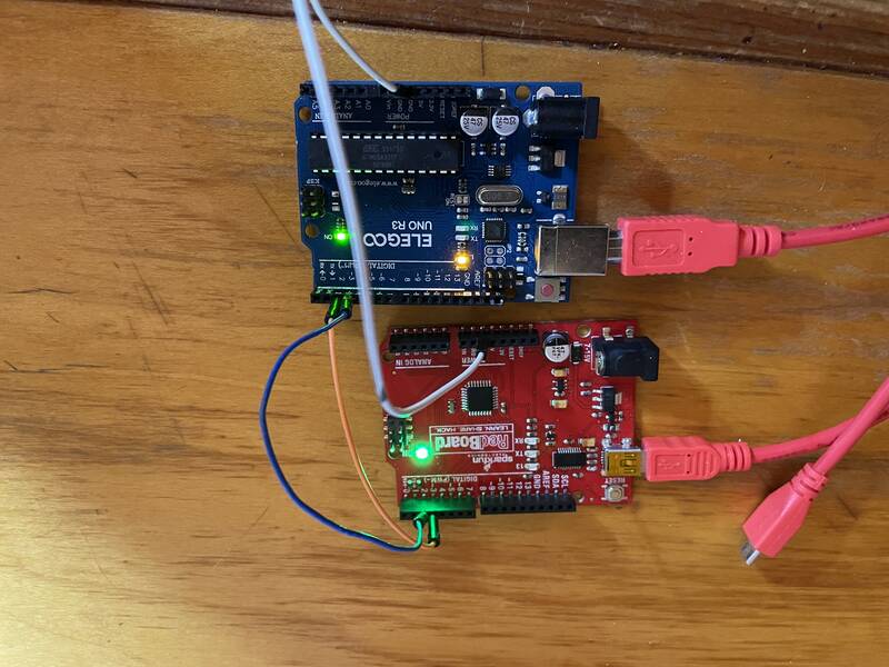
I uploaded this to two Arduino Uno clones, one from Sparkfun and one from Elegoo, and connected both to serial monitors on my PC. I connected the Unos' grounds together, and tied Pin 2 (Software serial receive) of one to Pin 3 (Software serial transmit) of the other, and vice versa.
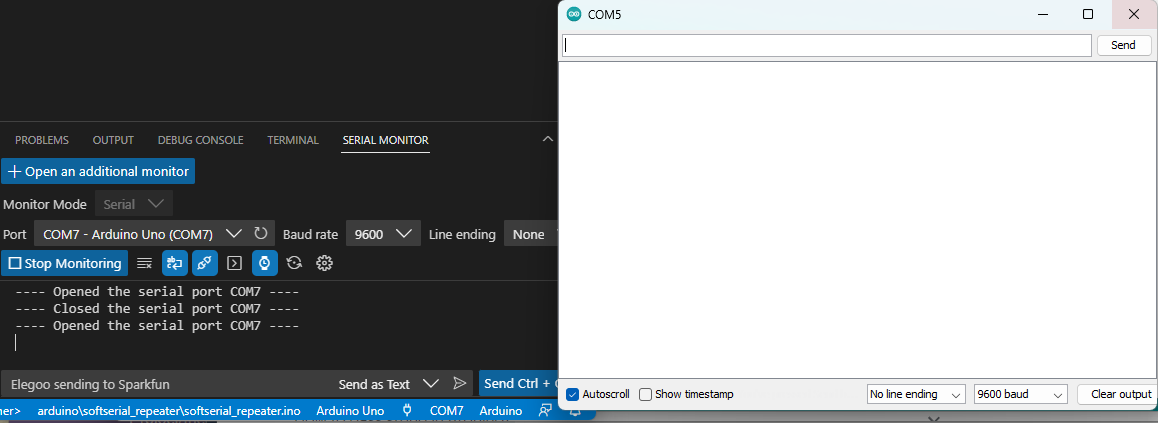
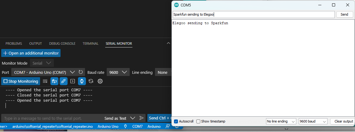
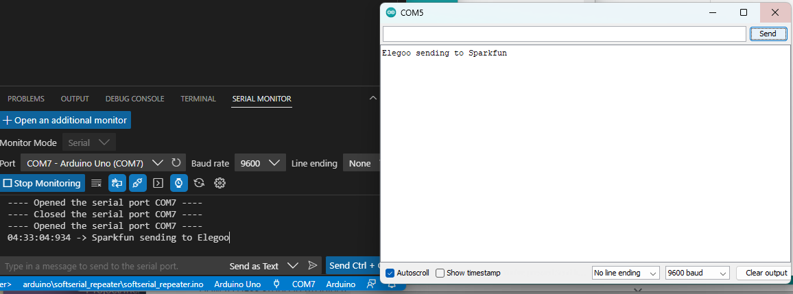
 When I type in a message into one serial monitor window, it appears on the other, as shown below:
Goal: Mastering I2C communications
My final project is going to involve a lot of I2C communications between a microcontroller and a bunch of magnetic field sensors. The sensors have configurable I2C addresses, so I'll be able to have many of them on the same bus ... so long as I can figure out how to assign them different addresses. I may also need more than the two I2C interfaces supported by the RP2040's hardware. So my task for this week is to get good at I2C communications. Here are my goals:- Demonstrate I2C communications between two microcontrollers, with custom I2C addresses
- Demonstrate software I2C on the Xiao RP2040
- Demonstrate I2C address configuration with multiple TMAG5273 sensors on the same I2C bus
Unfortunately, I ran into a bunch of technical problems accomplishing the first and second tasks, and wasn't able to get to the third. But I did do some extra work with I2C communications using CircuitPython instead.
I2C between microcontrollers
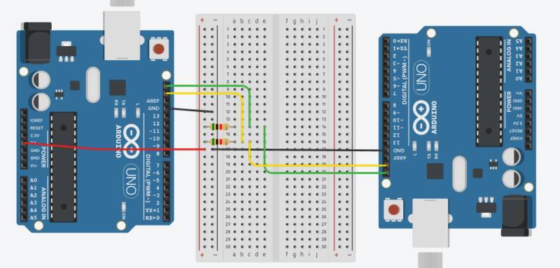
This should be easy, but the devil's in the details. My goal is to set up two microcontrollers and set one as an I2C "master" / primary and one as an I2c "slave" secondary and assign a custom I2C address to the secondary. The primary will send ASCII text to the secondary, which will reverse the order of the characters and send it back.Here are the key code snippets required for the primary:
  #include <Wire.h>
  Wire.begin();
  // Send data to address
  Wire.beginTransmission(address);
  Wire.write(data);
  Wire.endTransmission();
  // Request data from address
  Wire.requestFrom(address, numbytes);
  while(Wire.available()) {
    data = Wire.read(); // Read a byte at a time
  }
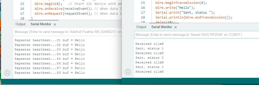
The secondary is more tricky, because it must only send and receive data when requested. This requires the use of event handler functions, which are outside the main program loop, and are only called when the I2C interface receives a request from the primary. They are called as interrupts, which means you can't do any other interrupt activities inside them. Printing to the serial port is an interrupt activity! This caused me a ton of problems, because serial port code I inserted to debug these functions caused them to not work.
The key code snippets required for the secondary are:
    #include <Wire.h>
    Wire.begin();
    Wire.begin(4);   // Start I2C device with address 4
    Wire.onReceive(receiveEvent); // When data is received, call receiveEvent
    Wire.onRequest(requestEvent); // When data is requested, call requestEvent

    void receiveEvent(int howMany) { // Receive event handler
      while (Wire.available()) {
        data = Wire.read();
      }
    }

    void requestEvent() { // Request event handler
        Wire.write(data);
    }
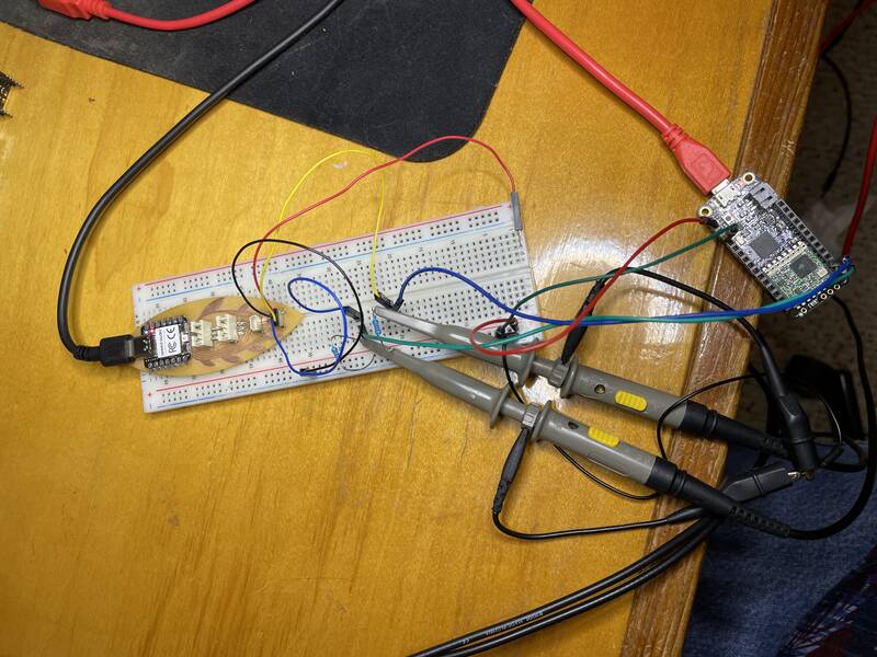
I first started working on this using my Beansprout RP2040 microcontroller and an Adafruit Feather M0 I had lying around. (Can't use an Uno with the RP2040 because the RP2040 is a 3.3V device.) I could not get it to work at all. When acting as primary, the RP2040 crashed immediately. When acting as secondary, it crashed as soon as it received a message from the primary. I tried some of the pre-made examples provided with Arduino (master_reader.ino, slave_sender.ino, master_writer.ino, slave_receiver.ino without success.)
To debug, I went back to trying to get two Arduino Unos talking to each other. THE SAME CODE WORKED PERFECTLY ON THE UNOS! This led to a ton of debugging work to figure out what was wrong with the RP2040 / M0 system. It took hours. A few of the things I tried:
- Swapping out microcontrollers
- Triple-checking wiring
- Reversing the role of primary and secondary
- Adding
Serial.print()lines to the event handlers to debug (this caused more problems due to interrupts) - Adding "heartbeat" Serial.print() lines to sender and receiver to figure out the exact moment of the crash
- Using an oscilloscope to trace the I2C signals
- Trying alternate I2C pins
- Trying alternate I2C addresses
- Trying other codes provided by the RP2040 Arduino platform author (these did not work as advertised on the Xiao RP2040).
- When setting up a microcontroller as primary, the Uno really doesn't mind if you give it an I2C address using
Wire.begin(address). The primary never uses this address, but the Arduino documentation says it's "optional". The RP2040 does care: a RP2040 as primary MUST be initialized withWire.begin()with no arguments. - For some reason the RP2040 refuses to act as secondary. Still not sure if I've written the code wrong, or if there's a bug, or if it's physically incapable. The good news is, I don't need it to do this for my final project, and I can satisfy this week's assignment with it only acting as primary.
Software I2C
The next thing I tried was to get software I2C working. In theory, it should be possible to use software "bit-banging" rather than a hardware interface to send I2C signals, which would allow me to have as many I2C interfaces as I'd like.I used the Arduino_Software_I2C library provided by Seeed Studios. I chose this library because it's from the same people that created the Xiao board I'm using, and because its programming interface is most similar to the Wire library used for hardware I2C. The drawback is that it's really poorly documented, and it can only act as a master (primary). But since I couldn't get the RP2040 working as a secondary with hardware I2C, this isn't a big deal.
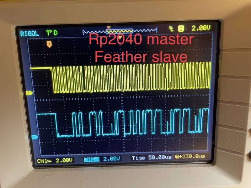
Another drawback is that I couldn't get it to work. I was able to send data back and forth to the "reverser" board, but the text was corrupted both in sending and receiving. Looking at the oscilloscope traces, the problem is apparent: the software I2C library doesn't generate a reliable clock signal (it pauses occasionally), and it looks like it "talks over" the receiving board's response. You can see some half-height digital pulses where one microcontroller is trying to assert HIGH and the other is sending LOW. I think the problem is that the software I2C library doesn't properly implement clock stretching, in which the secondary is supposed to be able to force the primary to wait by holding SCL low.
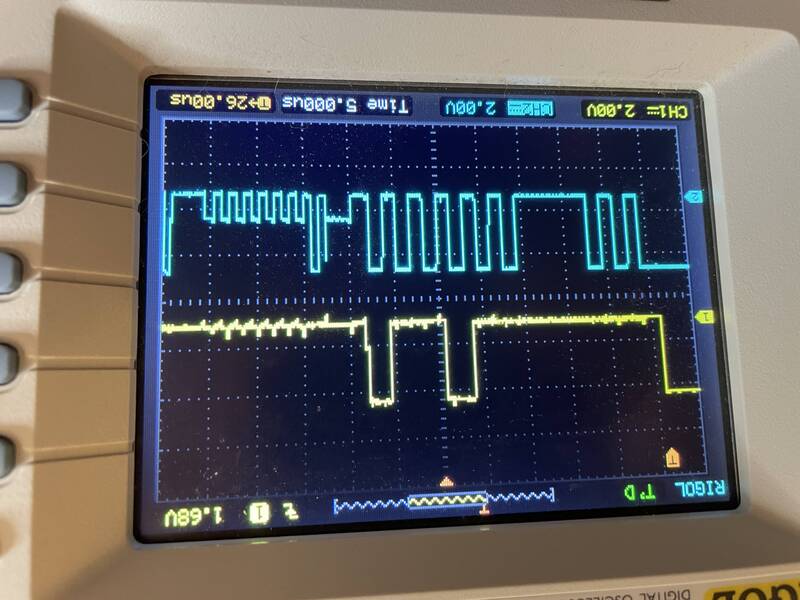
I don't have the time or expertise to fix this.
I2C with CircuitPython
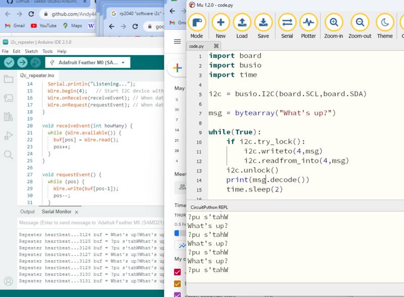
As a final effort, I tried to get I2C working within the CircuitPython platform. This turned out to be surprisingly easy! Here are the key code elements:
    import board
    import busio

    msg = bytearray("What's up?") # Message to send
    i2c = busio.I2C(board.SCL,board.SDA) # Start I2C

    if i2c.try_lock():          # Lock the I2C device so we an use it
      i2c.writeto(4,msg)        # Write the message to the secondary
      i2c.readfrom_into(4,msg)  # Get a response
    i2c.unlock()                # Unlock the I2C device so others can use it
TMAG5273 code for CircuitPython
Okay, one last thing. I did go ahead and write some CircuitPython code to interface with the TMAG5273 magnetometer chip that was the focus of Week 11. It's nowhere near a full library, just some bare-bones code to see if I can do it. I stole some I2C register-mangling functions from this site. Here's the output: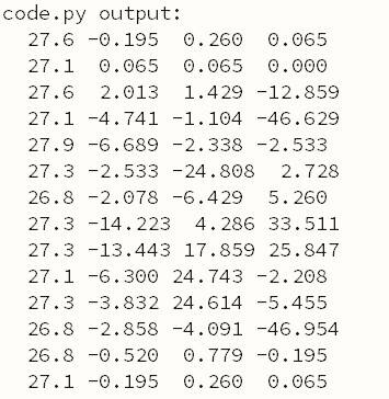
Design Files
softserial_repeater.ino: Echoes serial data received from softwareserial connection to hardware serial port, and vice versa.i2c_repeater.ino: Runs on secondary, receives data bytes and reverses them.i2c_sender.ino: Runs on primary, sends data bytes and prints out what it receives from secondary.softwarei2c_sender.ino: Same as above, but uses Software I2c. DOES NOT WORK.week13-i2c/code.py: Similar to above, but uses CircuitPython.week13-tmag/code.py: CircuitPython code to read and report data from TMAG5273 magnetometer.