Week 12: Molding and Casting
Checklist for this week:
- ☑ Linked to the group assignment page and reflected on your individual page what you have learned
- ☑ Reviewed the safety data sheets for each of your molding and casting materials, then made and compared test casts with each of them
- ☑ Documented how you designed your 3D mold and created your rough and finish toolpaths for machining, including machine settings
- ☑ Shown how you made your mold and cast the parts
- ☑ Described problems and how you fixed them
- ☑ Included your design files and 'hero shot' of the mold and the final object
Group Assignments
- Review the safety data sheets for each of your molding and casting materials
- Make and compare test casts with each of them
- Group Assignment Link
Individual Assignments
- Design a mold around the stock and tooling that you'll be using, mill it (rough cut +(at least) three-axis finish cut), and use it to cat parts
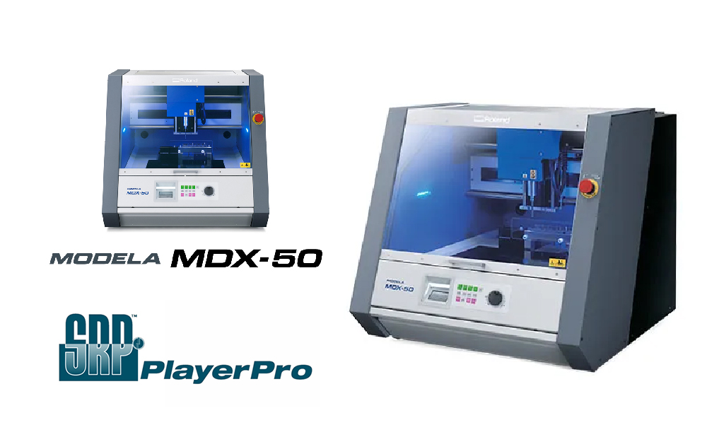
My individual assignment is to develop a design model and subsequently employ CNC milling to fabricate a corresponding mold. In my particular case, I have opted to utilize the Roland MDX 50 CNC milling machine for the fabrication process, while relying on Blender 3D as the software platform for designing the model.
Object model using Blender3D
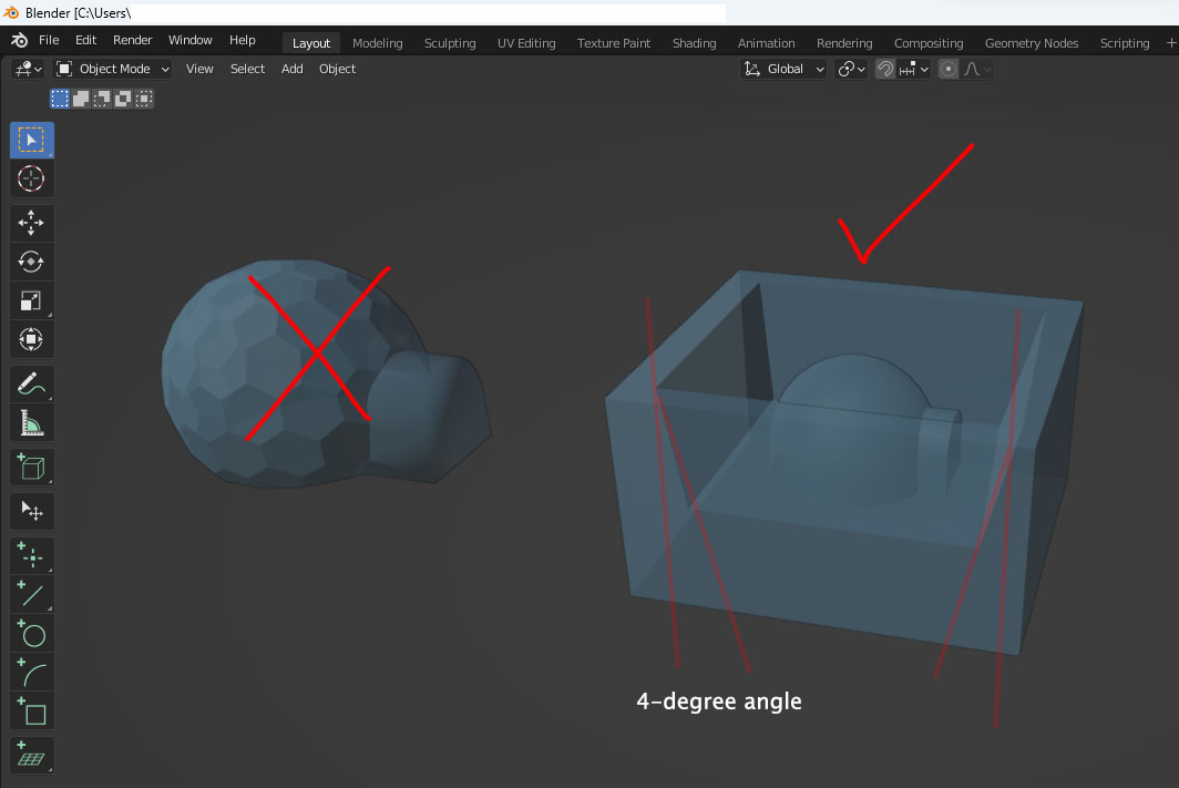
My thoughts are consumed by the Whale project constantly. I am currently struggling to generate a compelling idea for this week's assignment. As a result, I have decided to pursue a simplistic igloo shape. This choice will enable me to familiarize myself with the necessary steps involved in its creation, thereby allowing me to apply this knowledge to future projects.
Once the design is completed, I proceed to initiate the mold creation process for my igloo design. In doing so, I incorporate the utilization of a 4-degree draft angle (learn from my group member). This draft angle is implemented to ensure that the mold features a gradual taper, facilitating the smooth ejection of the molded part and minimizing the risk of any potential damage or sticking during the extraction process. By incorporating the 4-degree draft angle into the mold design, I aim to achieve optimal functionality and ease of use for the final product.
Milling the Mold
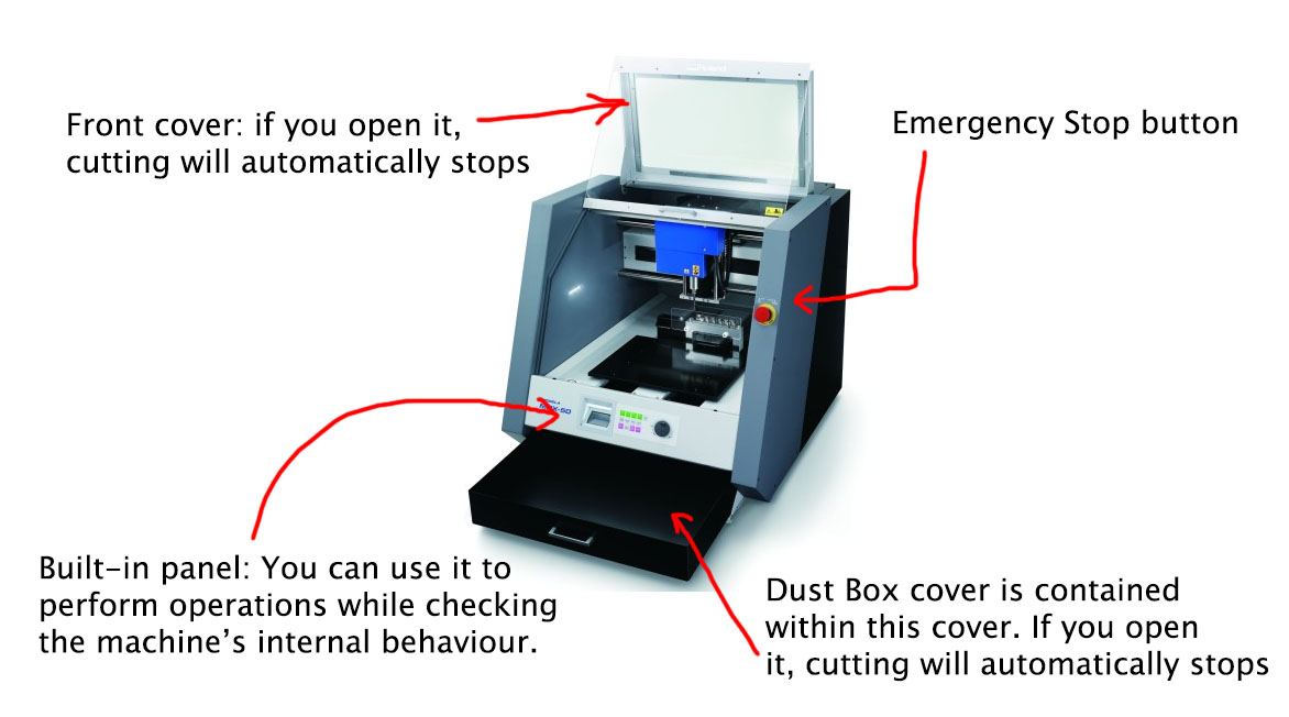
We have recently introduced the Roland MDX-50 Benchtop CNC Mill into our laboratory, featuring an innovative automated mill-changing capability. This cutting-edge machine offers two distinct modes of milling, effectively reducing the time required for the prototyping process. The first mode, known as DRAFTING, facilitates the creation of rough finishes, while the second mode, FINISHING, ensures an exceptionally high level of precision. By employing these modes in conjunction with pre-programmed adjustments, we can efficiently produce prototypes with a diverse range of finishes.
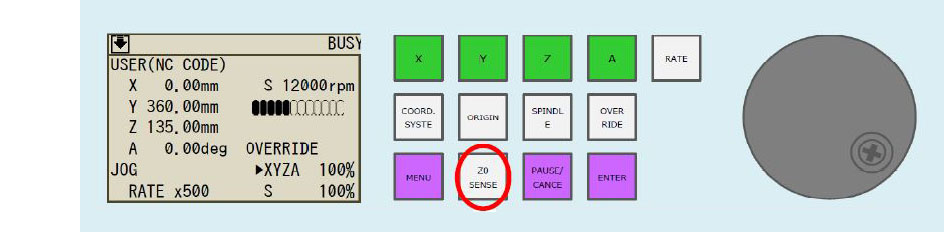
To initialize the machine for milling, we must first establish the starting points for the X, Y, and Z axes. This process aligns with the procedures we have followed for previous CNC machines during our work in week 7 (Computer-controlled machining) and week 8 (Electronics production). Initially, we access the front panel menu and select the mill-changing option. Once we have chosen the desired mill, the machine automatically switches to it.
Subsequently, we select the X-axis option from the same panel and utilize the hand wheel to rotate until the desired starting point is reached. Afterward, we choose the X-axis option once more and press the Origin button to reset the X-position to 0. The same procedure is repeated for the Y-axis by selecting the Y option and resetting its position to 0.
To establish the origin for the Z-axis, we open the door and position the sensor over the desired location on the material to be milled. Once positioned correctly, we close the door and press the "Enter" button on the front panel. Next, we select the "Z0 SENSE" option, prompting the machine to gradually lower the milling tool until it reaches the sensor. At this point, the machine automatically overrides the axis and sets the origin.
Moving on to setting up the milling characteristics, the machine presents a window with five steps for configuring the milling settings:
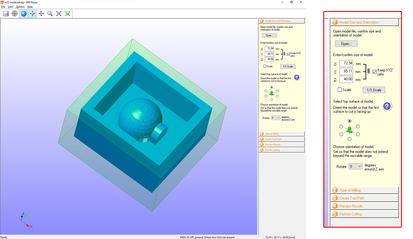
Model Size and Orientation:
Initially, I specified the original size of the model I intended to mill. However, I realized that the machine would require 8 hours to complete the milling process, which left only one day before the submission deadline. Consequently, I had to adjust the model's size to make it smaller. The software we were using allowed for resizing the model while maintaining the original proportions, with the addition of constraints to ensure it was reduced in size.Type of Milling:
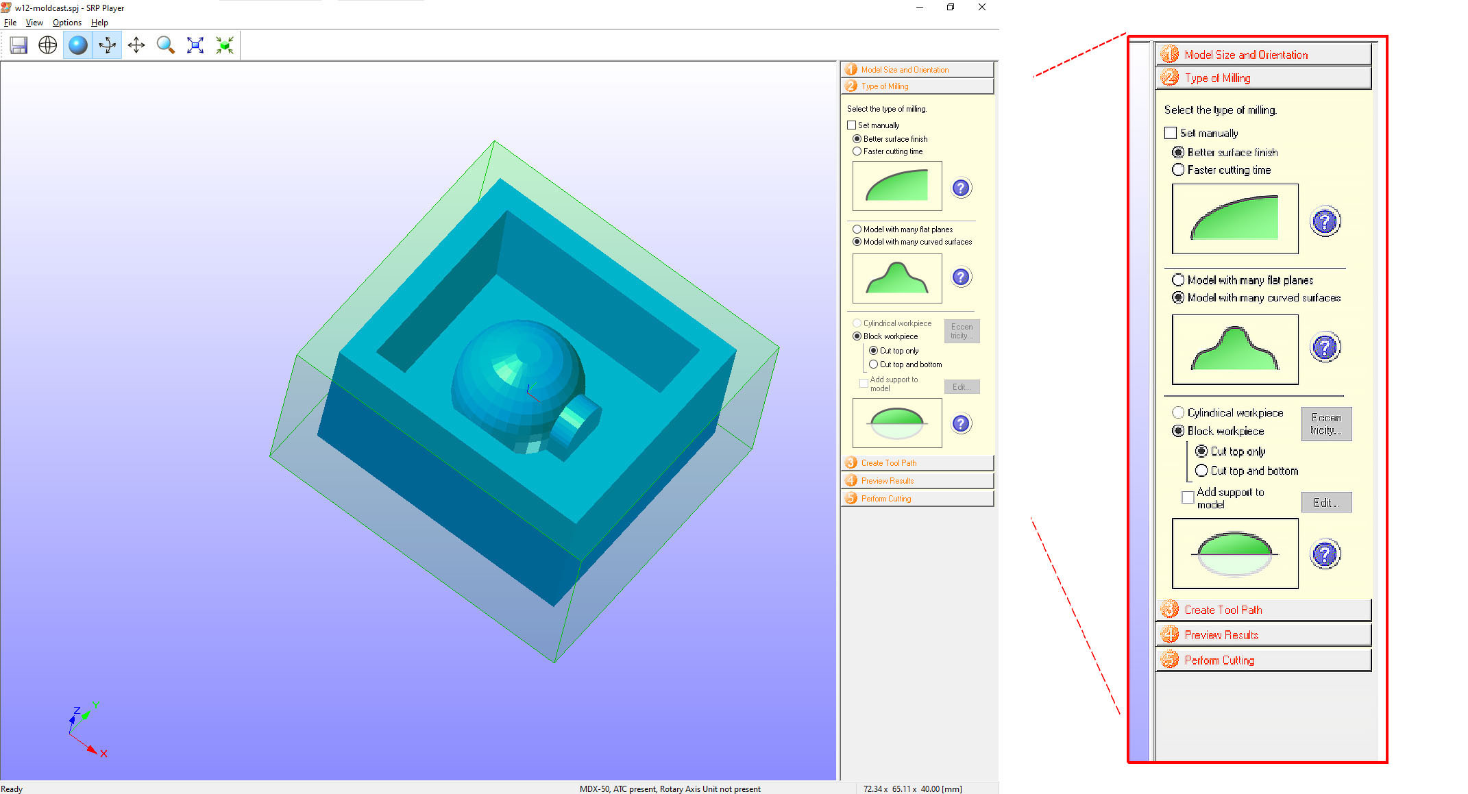
Within this window, I selected options that would yield the finest finishes, resulting in smooth curves. This capability is one of the notable advantages of this CNC machine, although it does increase the time required for milling.Creating the Tool Path:
At this stage, I specified the size of the actual material in which the object would be milled and positioned the object within it. I chose to align the object with the top of the material to minimize milling time. In this window, I selected the "Create Tool Path" option to proceed further with the milling settings.Preview Results:
In the "Preview Results" window, we can examine how both the rough and finishing settings will appear on the model. It provides a visual representation of the anticipated outcome.Perform Cutting:
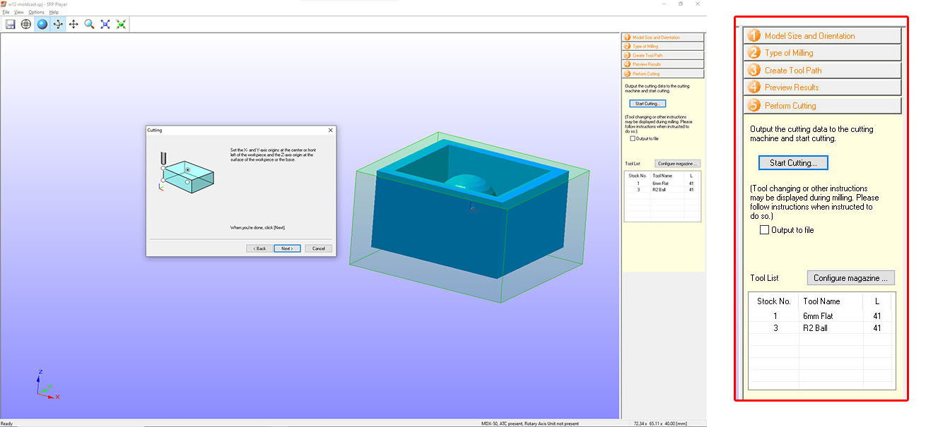
Finally, in the "Perform Cutting" window, we receive a summary of the chosen milling settings. In this case, as I commenced with the rough setting while turning off the finishing setting, only the mill for the rough setting, which is the 6mm flat mill, is displayed. Since I initially set the starting point for the X, Y, and Z axes in the middle of the piece of Styrofoam, I chose this as the mill's starting point. Upon clicking "Next," the machine initiates the milling process, automatically deploying the selected mill.
Once the rough finish was completed, I proceeded to mill the finishing pass. The entire milling process took a total of 2.5 hours (4pm ~ 6:30pm) to finish.
When milling a 3D model, there are two types of finishes to choose from. The first is called "Rough," which is suitable for creating preliminary sketches of 3D models where the final finish is not of significant importance. This type of finish typically results in a "terraced" appearance, as the machine only mills along the X and Y axes. We can also select the specific mill type for this finish. Given the expedited nature of rough milling, I opted for the 6mm flat mill. Additionally, it is possible to apply a specific finish to a particular area of the model. In my case, I selected the entire model for the rough finish (highlighted in orange).
The other setting available is "Finishing," where we once again select the type of endmill to be used. For this, I utilized the R2 ball mill, known for its ability to create fine, rounded surfaces. Similar to the rough finish, the finishing option can be applied to specific areas. In my case, I chose to apply this finish only to the Pentagon area of the design, while leaving the rest in the rough state.
The presence of these two settings provides us with greater flexibility. We can choose to activate or deactivate each setting individually by toggling them on or off. Alternatively, we can choose to activate both settings and execute them sequentially. I began by milling the rough setting. After inspecting the model without moving it from the milling station, I closed the door, pressed the enter button, and proceeded to turn off the rough setting while turning on the finishing setting. This allowed me to proceed with the final milling process.
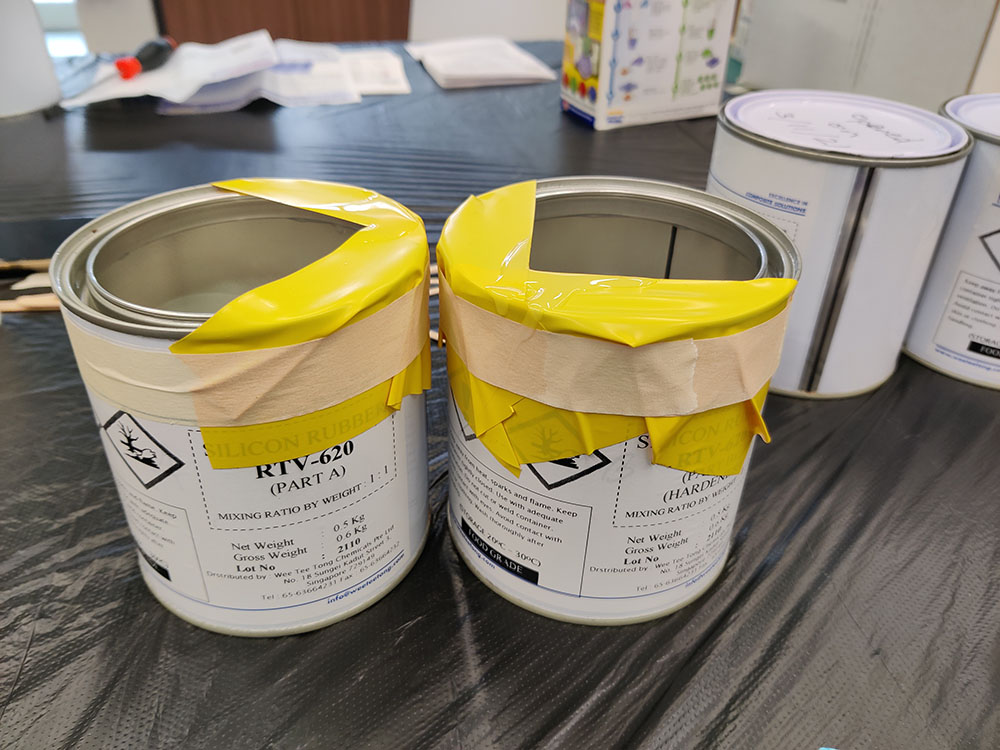
Silicon Mold Making with RTV-620
The handling of this particular material demands extra care and precautionary measures. It is imperative to wear gloves when working with it, as it can cause skin irritation. Additionally, it is essential to note that the material is highly flammable and must be handled accordingly. Disposing of it down drains is strictly prohibited, and proper containment measures should be taken before disposal.
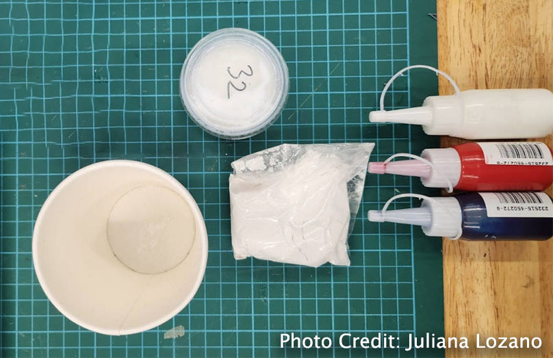
To facilitate the mixing process, we gathered the necessary materials, including plastic cups, mixing sticks, gloves, as well as mixture A and B. Furthermore, we took the precautionary step of covering the table to protect it from potential spills or stains.
Considering the small size of my mold, I opted for a more approximate approach in determining the required volume. Instead of precise measurements, I relied on visual estimation to determine the amount of material needed for my mold. This "eye-balling" method allowed me to gauge the volume required based on my experience and judgment. While this approach may introduce a degree of imprecision, it can still be effective for smaller-scale projects where exact measurements are not critical.
There is more scientific method to do this (that I learn from my course mate). The method for calculating the mixing proportions involves determining the required volume. Initially, my team mate introduced a certain amount of silicone pellets into the mold. Subsequently, she divided this volume equally into two cups, thereby obtaining the precise quantities of mix A and B needed to fill the mold. Once the two parts of the mixture were accurately measured, she combined them in a separate container.
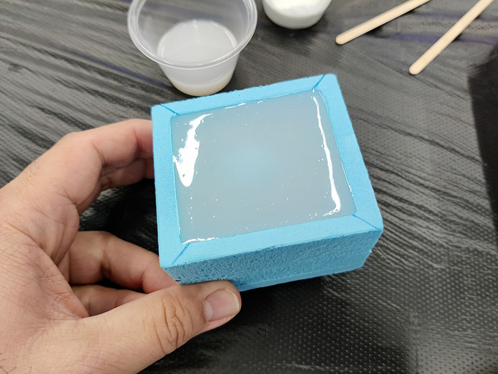
During the mixing process, it was crucial to stir the mixture for approximately 15 minutes, taking care to minimize the introduction of air bubbles.
With the mixture now prepared, I proceeded to pour it slowly into the mold, ensuring a controlled and gradual flow to prevent the formation of bubbles. Subsequently, I allowed the mold to cure for a period of 24 hours to ensure proper solidification and setting of the material.
Casting
I proceeded with the casting using a remarkable material called JESMONITE, which offered several favorable characteristics. JESMONITE is known for being eco-friendly, user-friendly, and capable of achieving astonishing results. It is an acrylic polymer/ mineral resin, and detailed information can be found in the provided TECH SHEET.
For the measurement of the required quantity of material, weight served as the unit of measurement. To begin, my course mate placed the mold in a box and positioned it on a scale, subsequently resetting the scale to zero. She then poured water into the specific section of the mold where the casting was intended. This step allowed her to determine the precise quantity required. Having obtained the weight measurement of the mold space, she divided this quantity in half, resulting in the required amount of Jesmonite Liquid, which was 50/2 = 25 grams. To determine the amount of powder needed, she multiplied the liquid quantity by 2.5, yielding 75 grams of powder.
Or you could use the Jesmonite calculator.
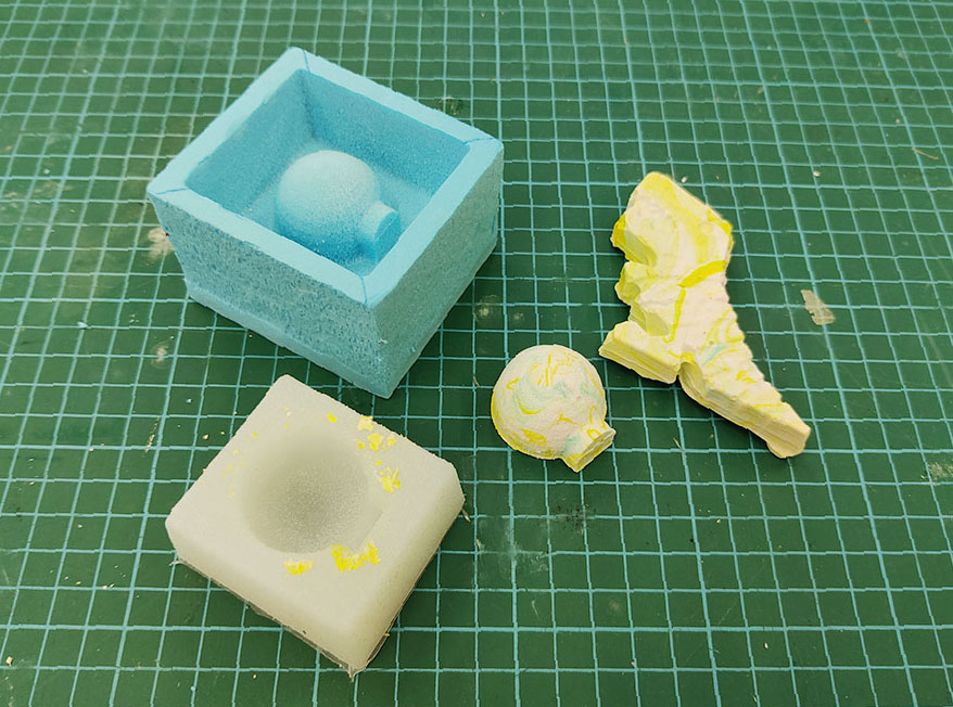
Once again, considering the smaller size of the mold I prepared, I use a pre-packed JESMONITE components available in the Fablab. Proceeding to the mixing stage, I combined the two components (liquid and powder) in a cup, using a flat spoon to ensure thorough blending. The mixing process proved to be effortless, as the powder dissolved quickly and easily. I also added a few drops of liquid colorant to the mixture, aiming for a pastel-tone finishing. Subsequently, I carefully poured the mixture into the mold and allowed it to cure for approximately 30 minutes, during which it solidified rapidly. The remaining JESMONITE is poured into a cartoon dinosaur mold that I found in the lab.
Problems/ reflections
The milling process experienced "longer operating hour than necessary" that could have been avoided by adjusting the settings. For instance, omitting the milling of the outer line of the mold, which was unnecessary, would have helped reduce time. Additionally, opting for a less detailed finish might not have significantly impacted the overall outcome.
As evident, the mold and casting process hold great potential and are intriguing. However, at present, my focus and attention are primarily directed towards the Whale project and meeting its delivery deadline. I intend to revisit this chapter in the future when I have more time and resources to dedicate to it.
Hero Shot
3. Link to files
- Blender 3D file (.blend)
- 3D model of mold (.stl)