Week 8: Electronics Production
Checklist for this week:
- ☑ Linked to the group assignment page
- ☑ Documented how you made (mill, stuff, solder) the board
- ☑ Documented that your board is functional
- ☑ Explained any problems and how you fixed them
- ☑ Uploaded your source code
- ☑ Included a 'hero shot' of your board
Group Assignments
- Use the test equipment in your lab to observe the operation of a microcontroller (MCU) circuit board (as a minimum, you should demonstrate the use of a multimeter and oscilloscope)
- Document your work on the group work page and reflect what you learned on your individual page
Individual Assignments
- Design a development board to interact and communicate with an embedded microcontroller
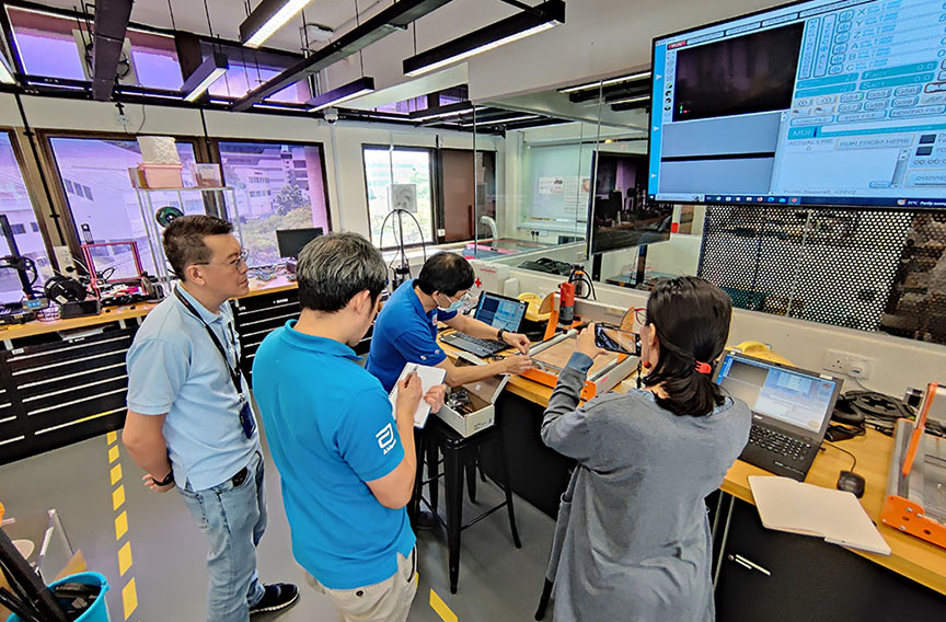
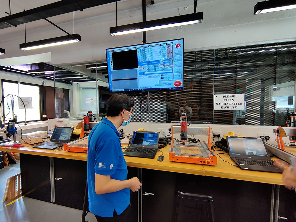
Using Desktop mill Stepcraft
We have successfully generate the layout of the PCB and G-code from previous week. This week we are going to load the G-code into the Stepcraft milling machine to start production of the PCB board.
Here is a recap of the mobs setting (online server) to generate the G-code. Online mobs server: http://mods.cba.mit.edu/
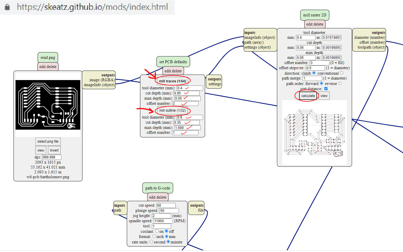
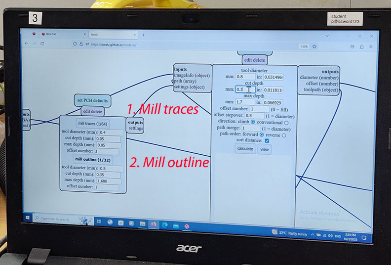
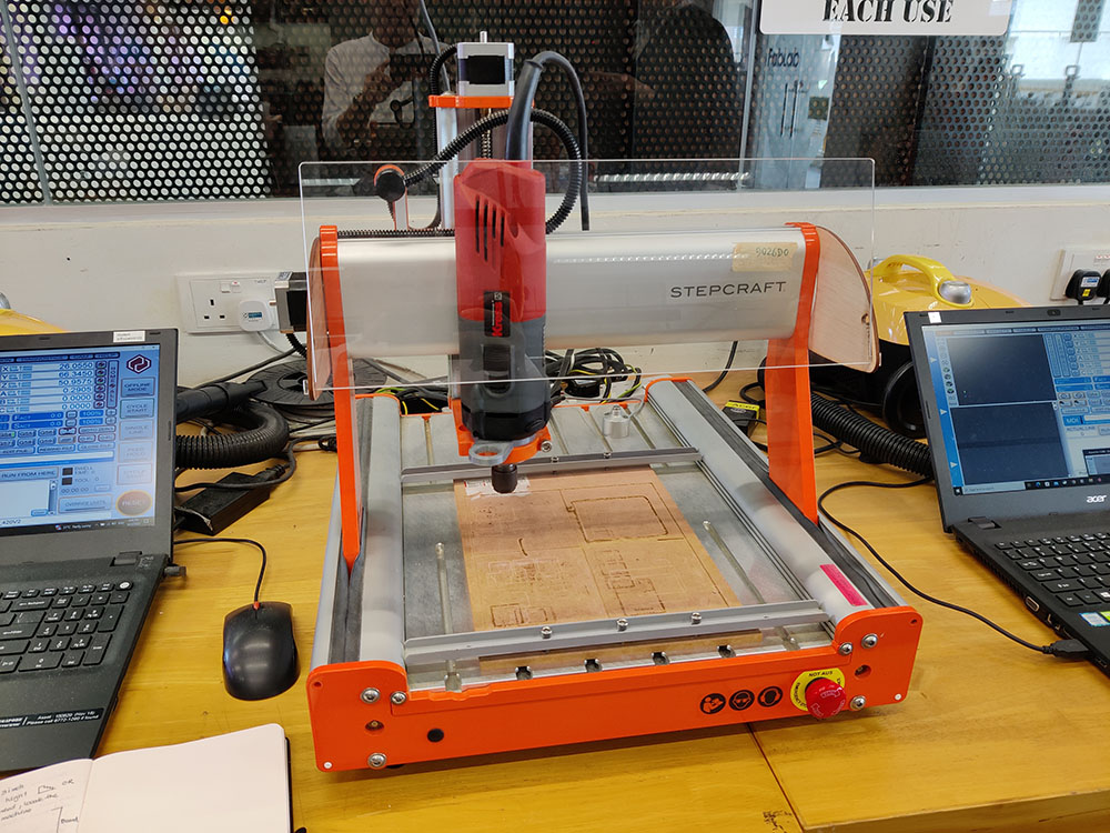
Milling the PCB
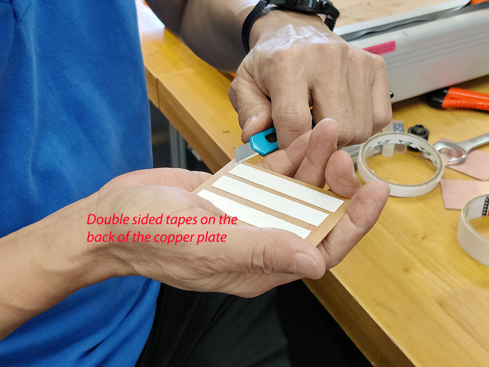
1. We tape the copper plate on the router bed (Double-sided tape in the back) and masking tape on the sides.
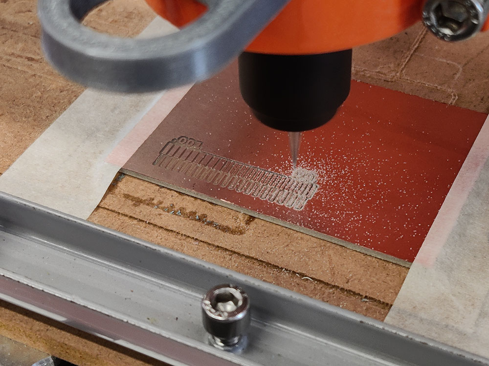
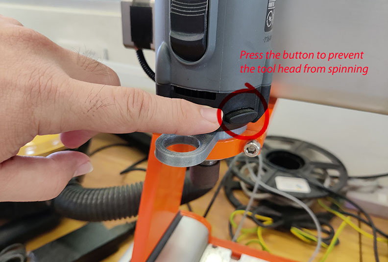
2. Change to the right size End-mill. There are a few type of End-mill that measure 0.4mm but only one works for the best (so far). Every change of end-mill, we have to re-do z-axis calibration. In the situation that the end-mill doesn't cut deep enough, we increase the depth manually by 0.025mm each time.
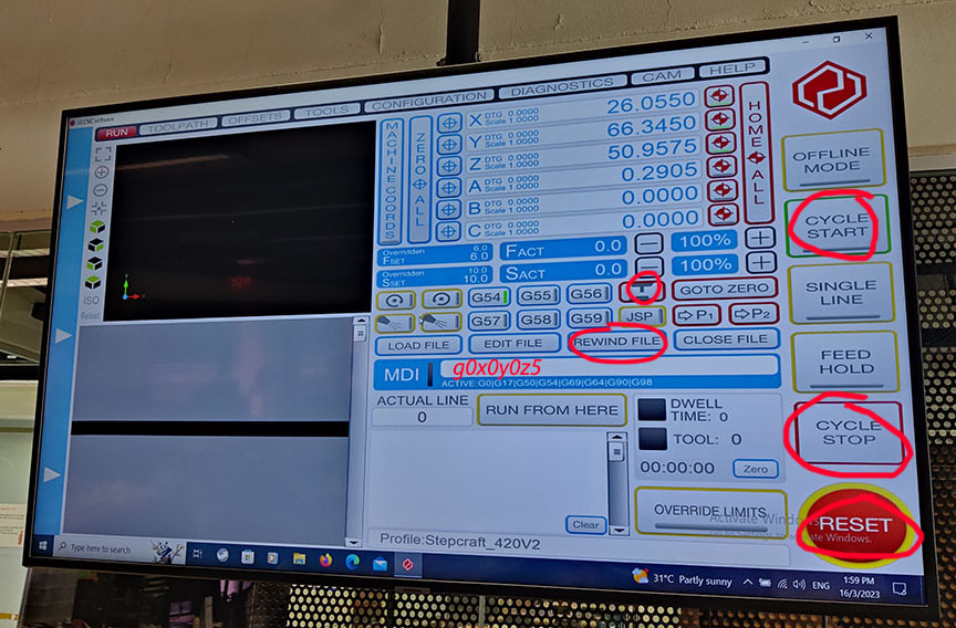
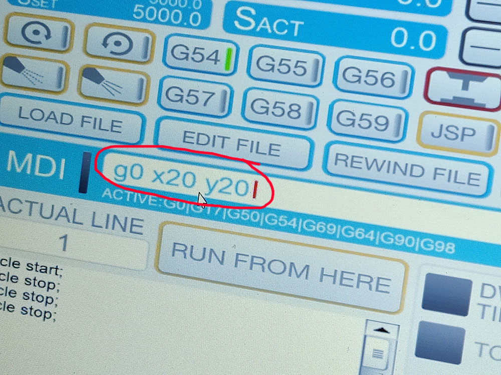
3. Set the origin for X-axis and Y-axis. Double-check the cutting boundary (all around the paths) with the pointer at the screen to make sure the milling doesn't exceed the size of the board we are milling.
4. Manually switch on the Milling machine BEFORE we click on CYCLE START!
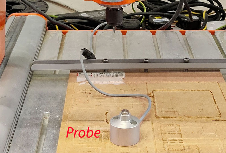
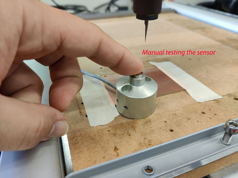
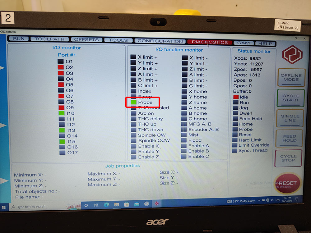
5. After finish milling the traces (0.4mm End-mill). We need to mill the holes and then the outline of the PCB. We need to change to 0.8mm End-mill. With tool head changed, we need to calibrate the Z-axis again with the Probe. We don't need to change the x-axis and y-axis origin. Manually turn on the milling machine BEFORE click on CYCLE START.
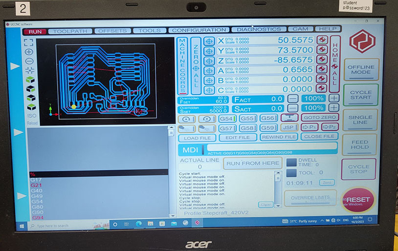
6. Once the Holes are done we open the G-Code for the Outline to finish the 3rd part (final) of the milling.
Final check on the PCB
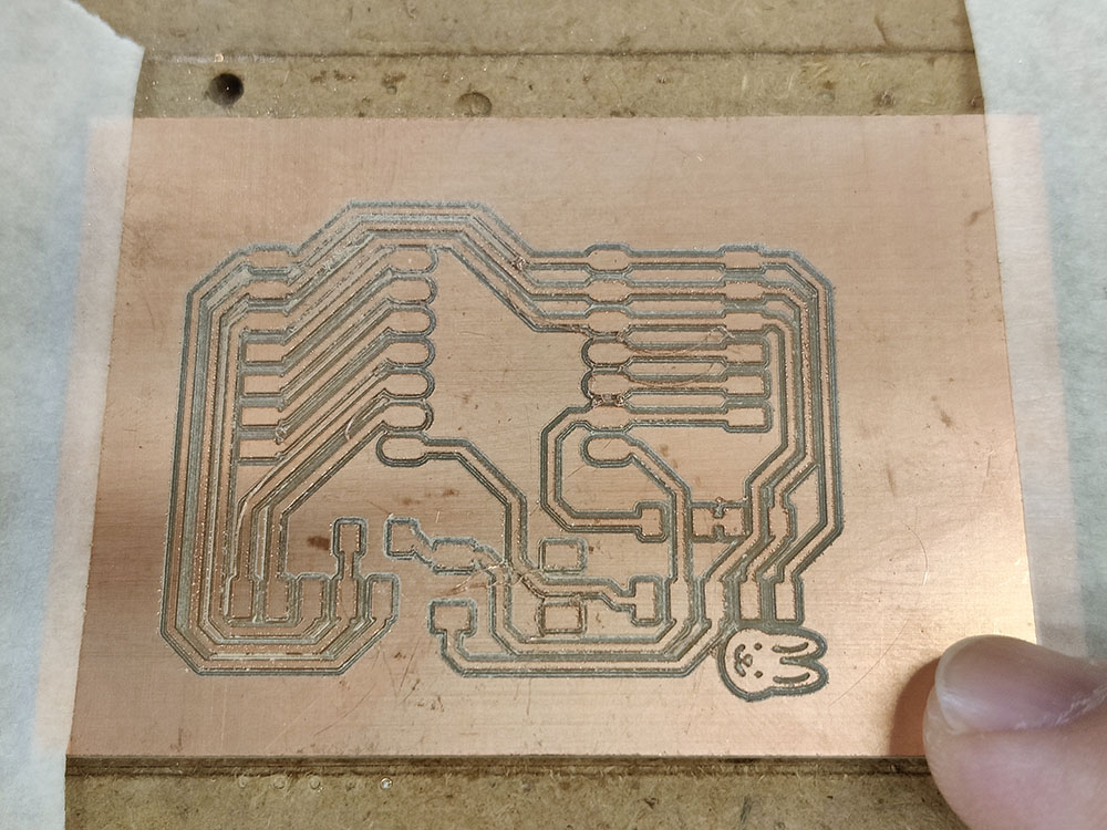
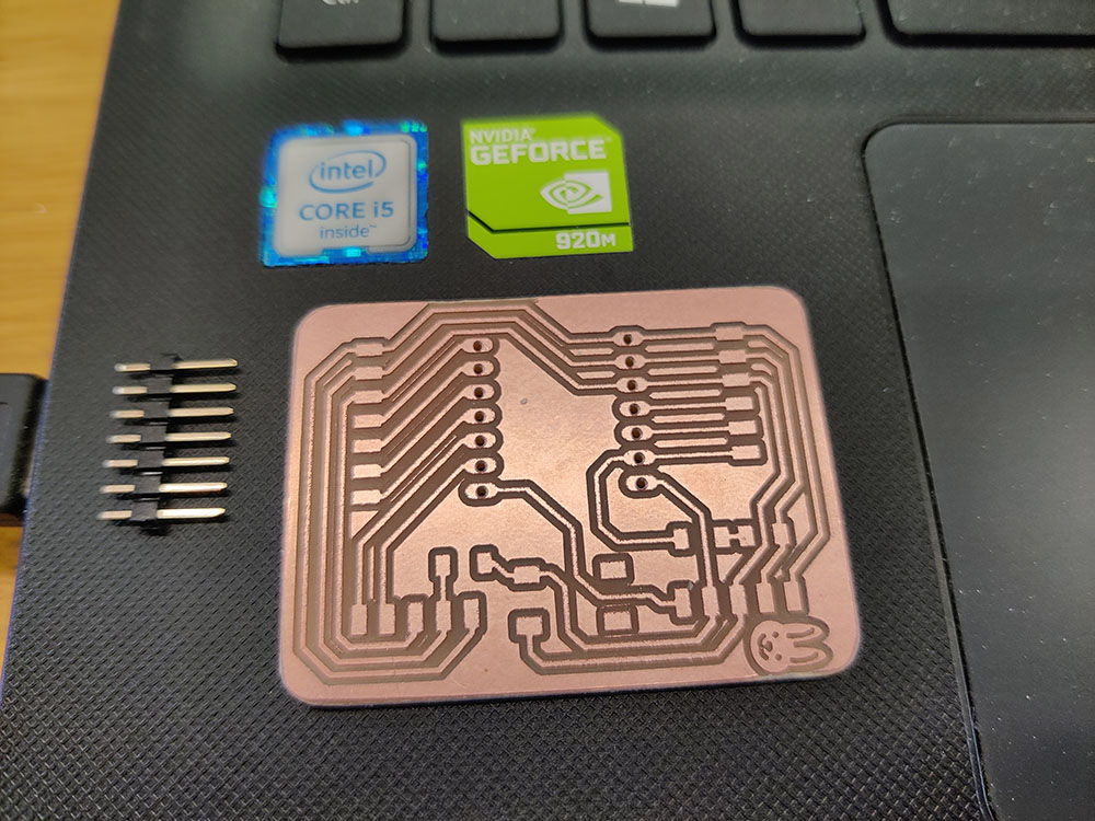
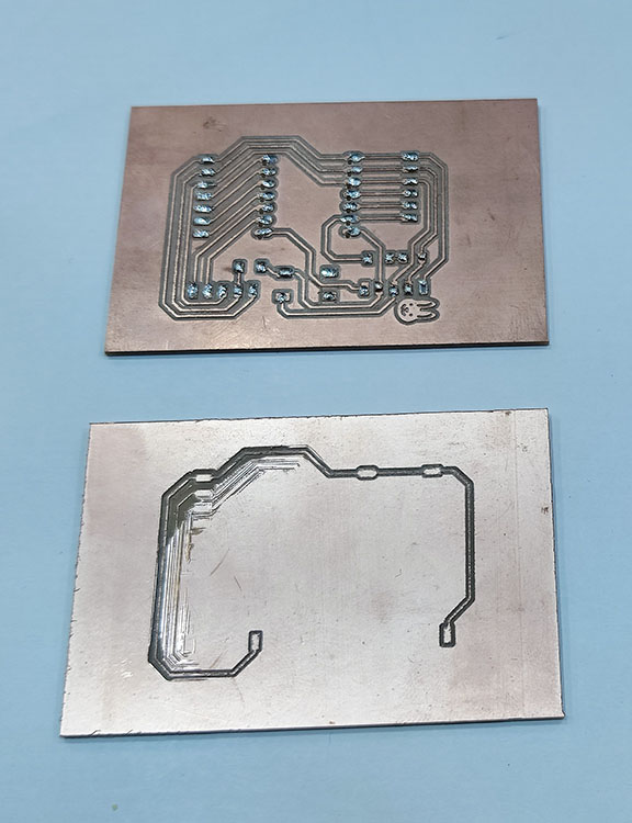
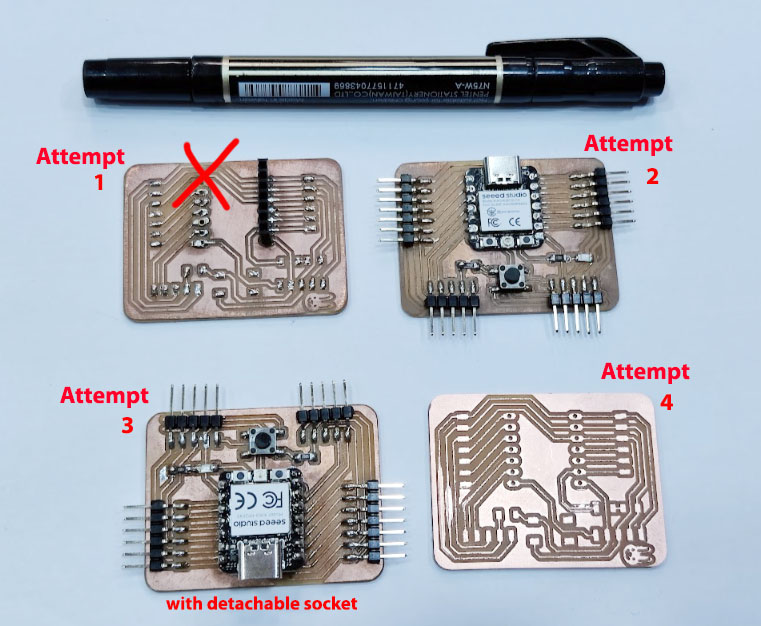
Two failures along the way for the milling, mostly is unevenness of the milling bed. Below is the fourth attempt and there is imperfection on the bottom left of the milling but it passed the continuity test using a multimeter. In total, I have 3 successful PCB board (before soldering).
Soldering the Xiao RP2040 to the PCB
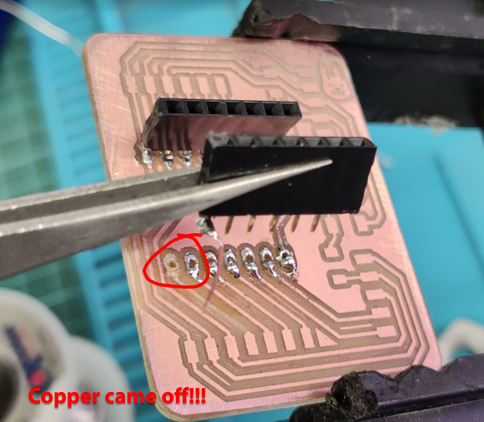
The first attempt was too ambitious to solder a detachable XIAO RP2040. The sockets that connect the XIAO RP2040 with multiple legs are difficult to align properly during soldering. In the end, I accidentally pulled too hard and the copper came off the board. So back to milling machine for a new PCB board.
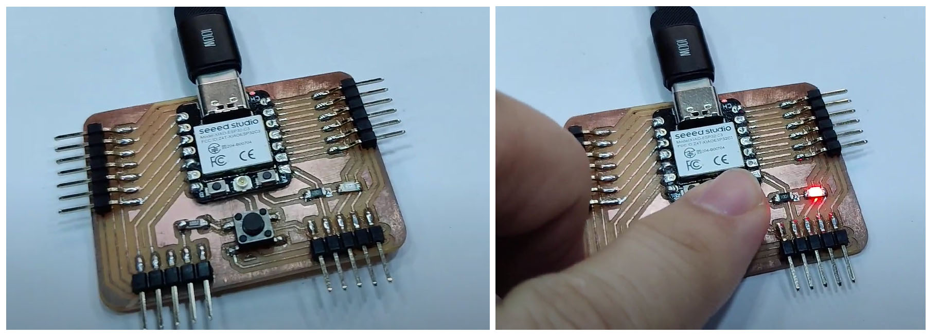
I started watching youtube videos for soldering tips and they helped theoretically. I bought two sets of ESP32C3 a few weeks ago from Taobao and I thought I could have at least two more failures. On the second attempt, I soldered the XIAO ESP32C3 chip onto the PCB directly and test the press button and LED (red). It is very satisfying to see it work! With the successful attempt, I am hooked with soldering. I continue to mill my third and fourth PCB ready to practice my newly acquired soldering skill. My third attempt I go back to the socket soldering method. It was not easy but I got them soldered on.
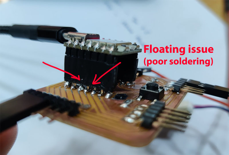
Something I learnt along the way is the component "floating" around the soldering area, which give the component (e.g. LED) unpredictable results. Multimeter is good tool to check the continuity of the soldering component.
Checking the Push Button
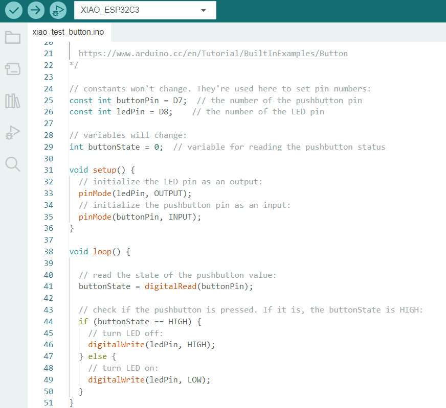
The button is connected with 10k ohm pull-down resistor to the GND (Pin D7) while the SMD green LED is connect to pin D8. The resistor is connected to the Ground so it is considered a pull-down technique. Below is the code to test the button and the LED.
The push button is connected to Pin D7 and the onboard SMD LED is connected to Pin D8. When the button is pressed, the state of the button become HIGH, and the condition for the LED to light up (digitalWrite HIGH).
About the code, we created variables buttonPin, ledPin, and buttonState. In the setup, we stated that pinMode D8 as input and D7 as output. The rest of the code is explained in the comments after //.
The board is WORKING (finally)!
The button is connected with 10k ohm pull-down resistor to the GND (Pin D7) while the SMD green LED is connect to pin D8. The resistor is connected to the Ground so it is considered a pull-down technique. Below is the code to test the button and the LED.
The push button is connected to Pin D7 and the onboard SMD LED is connected to Pin D8. When the button is pressed, the state of the button become HIGH, and the condition for the LED to light up (digitalWrite HIGH).
About the code, we created variables buttonPin, ledPin, and buttonState. In the setup, we stated that pinMode D8 as input and D7 as output. The rest of the code is explained in the comments after //.
Learning opportunity for SMD Resistor
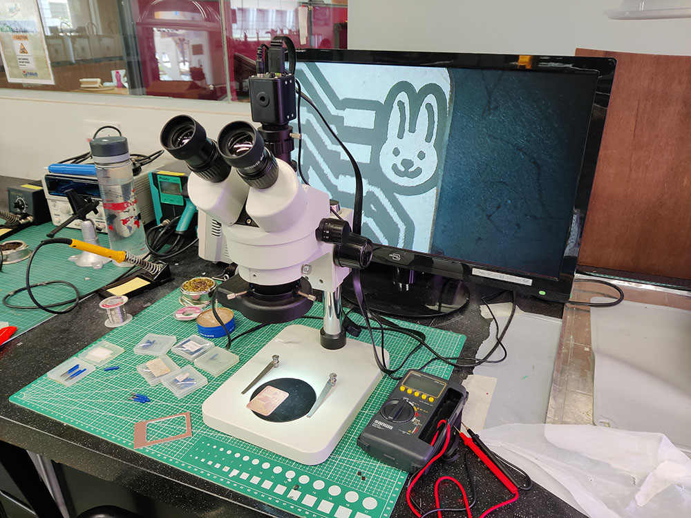
SMD Resistor Code Calculator indicated clearly what is the code number you should be looking at to solder on your PCB. I mistaken 105 (10 * 10^5) for 10k Ohm while I should be using 1002 (100 * 10^2) for my pull-down resistor on my button, while thinking where else did I do wrong. Luckily my colleague point out my mistake after putting it under the microscope.
To remove the SMD components: First test the hot air gun on an unwanted board with solder and observe the solder when it melt successfully within 5 seconds. Then move on the actual SMD component to be removed. Use a tweezer to hold the component after it's being heat up. Under gravity, the PCB will fall off and separate the SMD component.
About soldering mistake
Personally I find flux is so under-appreciated when it comes to soldering as your wire or components are exposed to open air for long. I watched this video and it helped me to understand.
During week 9 Asia review, I also learnt that there is liquid flux that I could apply so it is less messy. I bought a few bottles to test out in coming weeks.
Another important misperception that I had about soldering iron was that it could be used as a "stick to push the icing on cake". The only purpose for soldering iron is for heat transfer MOSTLY. If the heat is dissipated properly to liquefy the soldering wire, everything will fall into places as they should. If oxygenated surface(s) is preventing proper bonding of the solder wire, apply flux (or use rosin solder wire) for better soldering result.
Lastly, use Isopropyl Alcohol (IPA) to clear or wipe out excessive flux if necessary. Sometimes the flux may look like a burn mark but IPA should clean them up.
Tips for improving milling quality on Stepcraft:
- Bit dull (time to change end-mill)
- Feedrate/ spindle speed: 60mm / min @ 11,000~12,000 rpm
Update
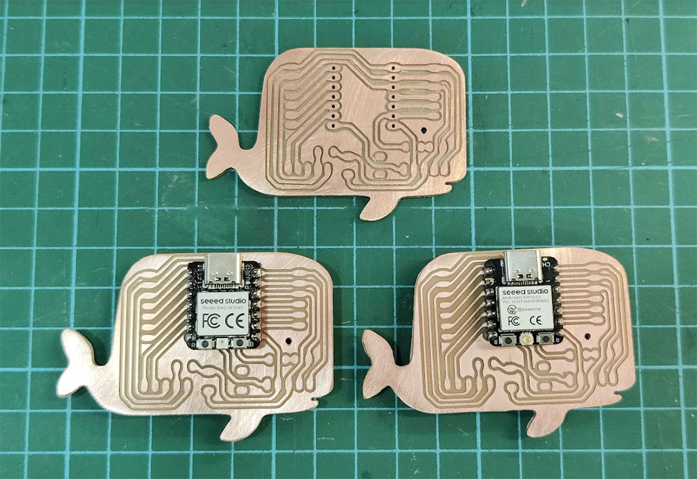
In week 18 of the project, I completed the milling process for three new PCB (Printed Circuit Boards).
Links to working files