Week 7: Computer Controlled Machining
Checklist for this week:
- ☑ Linked to the group assignment page
- ☑ Documented how you designed your object (something big)
- ☑ Documented how you made your CAM-toolpath
- ☑ Documented how you mae something BIG (setting up the machine, using fixings, testing joints, adjusting feeds and speeds, depth of cut etc)
- ☑ Described problems and how you fixed them
- ☑ Included your design files and 'hero shot' of your final product
Group Assignments
- Complete your lab's safety training
- Test runout, alignment, fixtures, speeds, feeds, materials, and toolpaths for your machine
- Document your work to the group work page and reflect on your individual page what you learned
Individual Assignments
- Make (design+mill+assemble) something big
Designing first CNC project
This documentation may be brief but I assure you that there are NO shortcuts during the making. Every steps are carried out by my own hands- from design to mill and assemble.
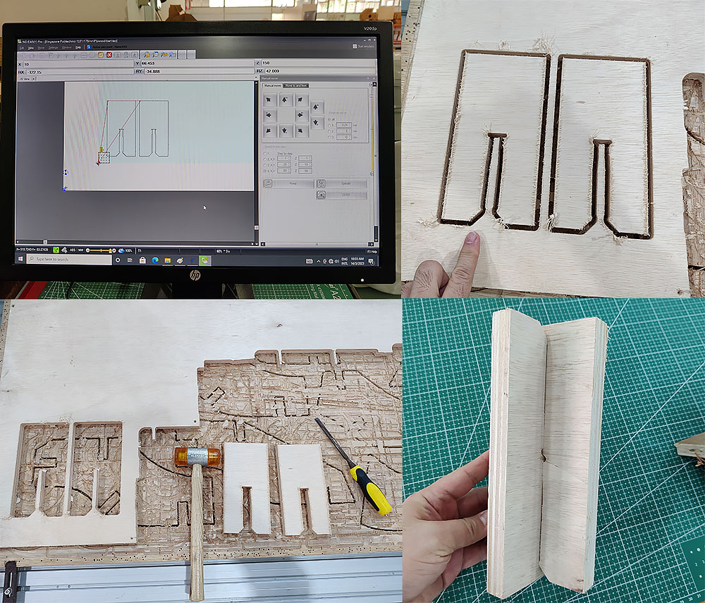
This week has been one of the most enjoyable week for myself because I have always want to start using the CNC milling machine in our fablab. Finally, I built something out and assembled it without screw or glue. The fitting test help a lot with the size of the slots to make it tight-fit once the slots are in.
The design process
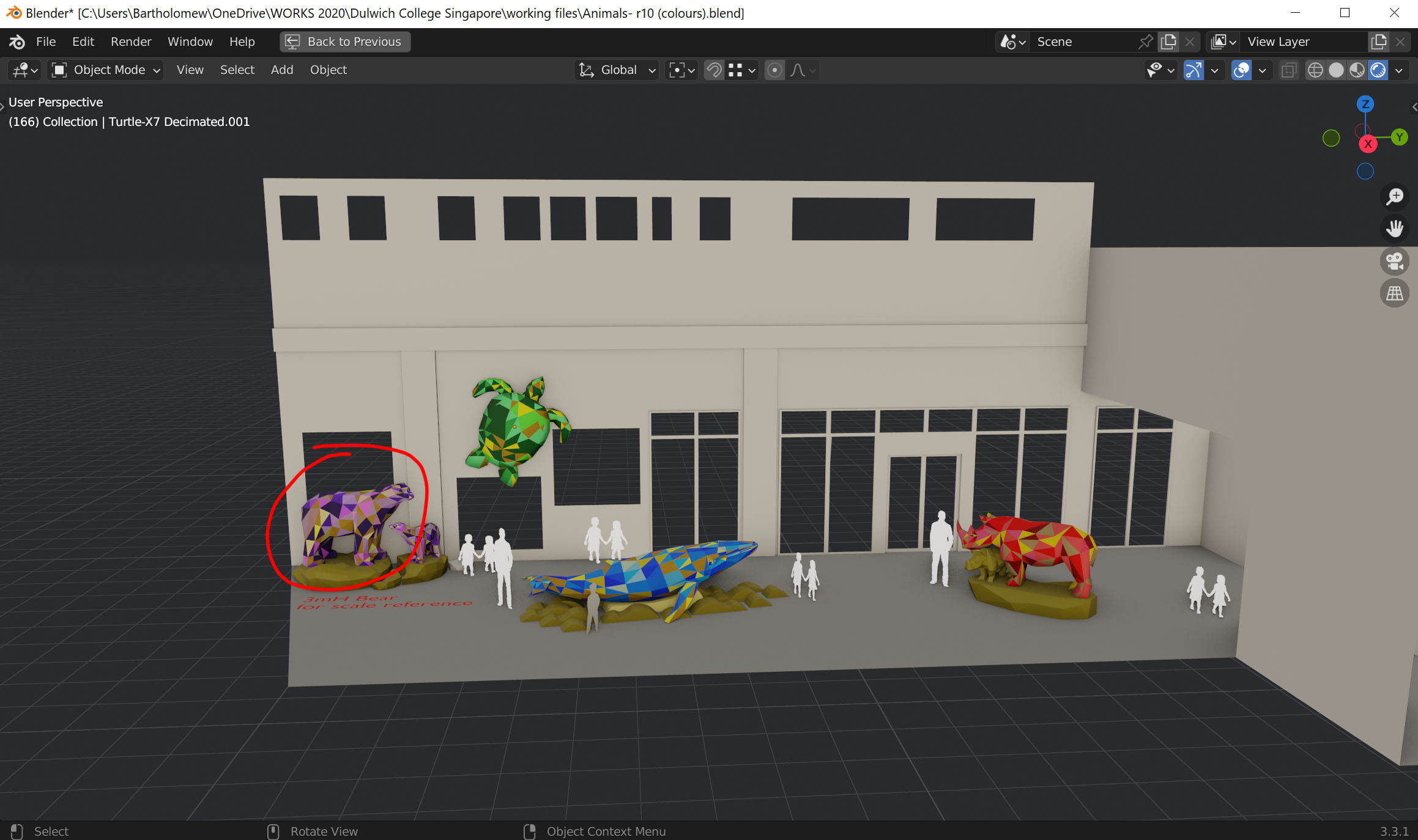
I designed a few animal sculptures in 2020 for an international school. You could click on the following photos to view the album. I re-use the digital model again this time know that time is not on my side. I shrunk the size to about 1.6m in length to fit in plywood (2440 x 1220mm) provided. Took a few to-and-flow to come to the final size but it is worth the effort.
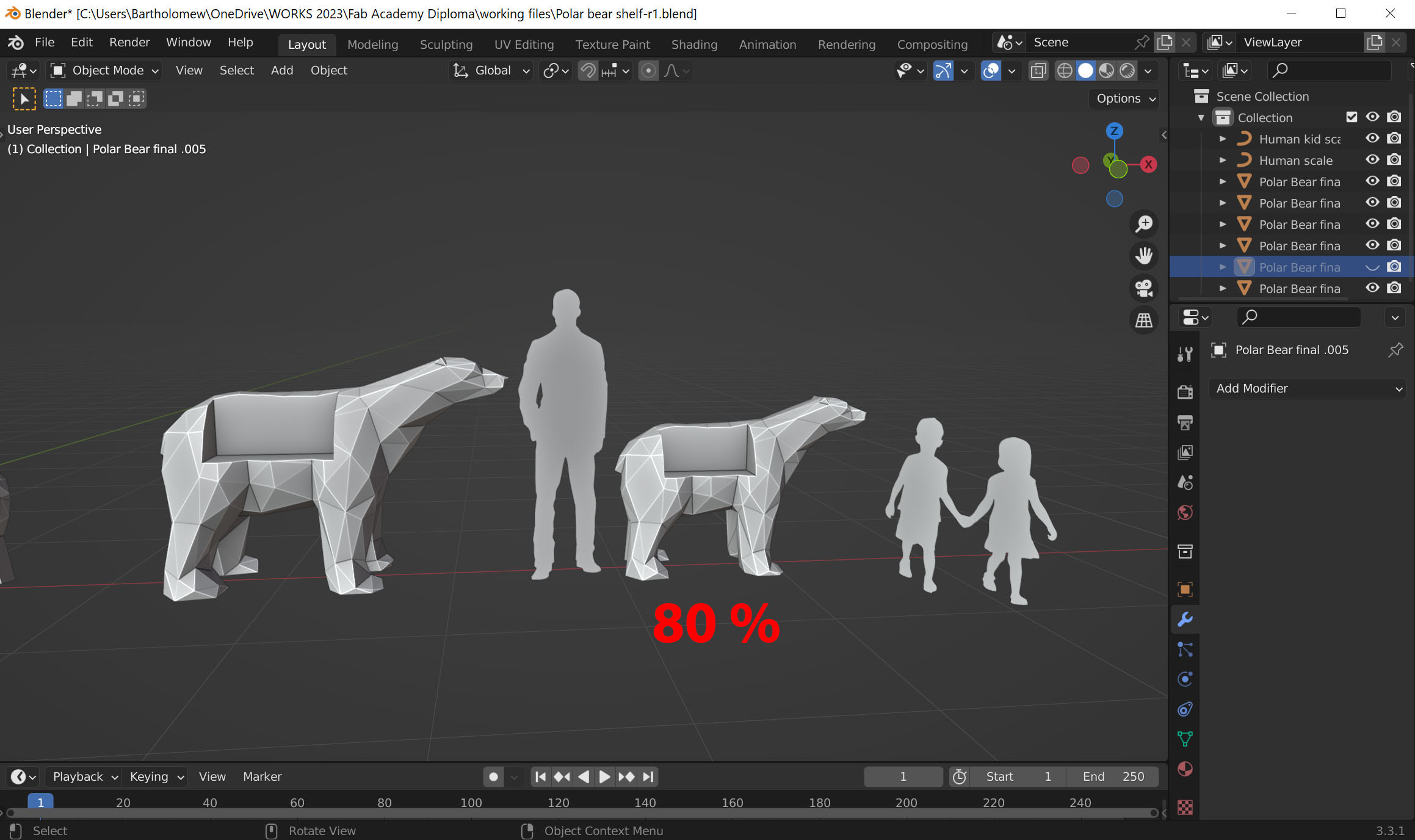
Parametric Design- adjusting the material thickness from 12mm to 18mm
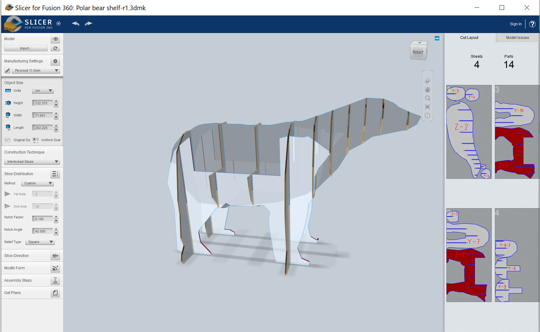
Originally I was planning to cut on 12mm plywood but to prove that my design is parametric-centric, I changed the material thickness in the software "Slicer for Fusion360".
Slicer for Fusion 360 (79.2Mb, last updated: year 2020). The app is no longer maintained by Autodesk since years ago but you could still download it by google the app name. Also, the name "slicer" is irrelevant nowadays as the 3D printing industry use it for different meaning. But personally, I find this app is still useful at times!
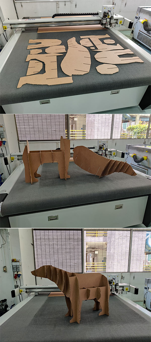
Cardboard Prototype first!
Originally planning to mill on plywood about 12mm. So I shrunk the cardboard to 50%. The thickness of the cardboard is about 5.5mm (about 50% of the plywood).
CAM Design
I use the Adobe illustrator to do my layout before sending to VCarve-pro for toolpaths design. We did a test cut for the fitting test and speed test last week as a group. This time I manage to set all up by myself and luckily all went well.
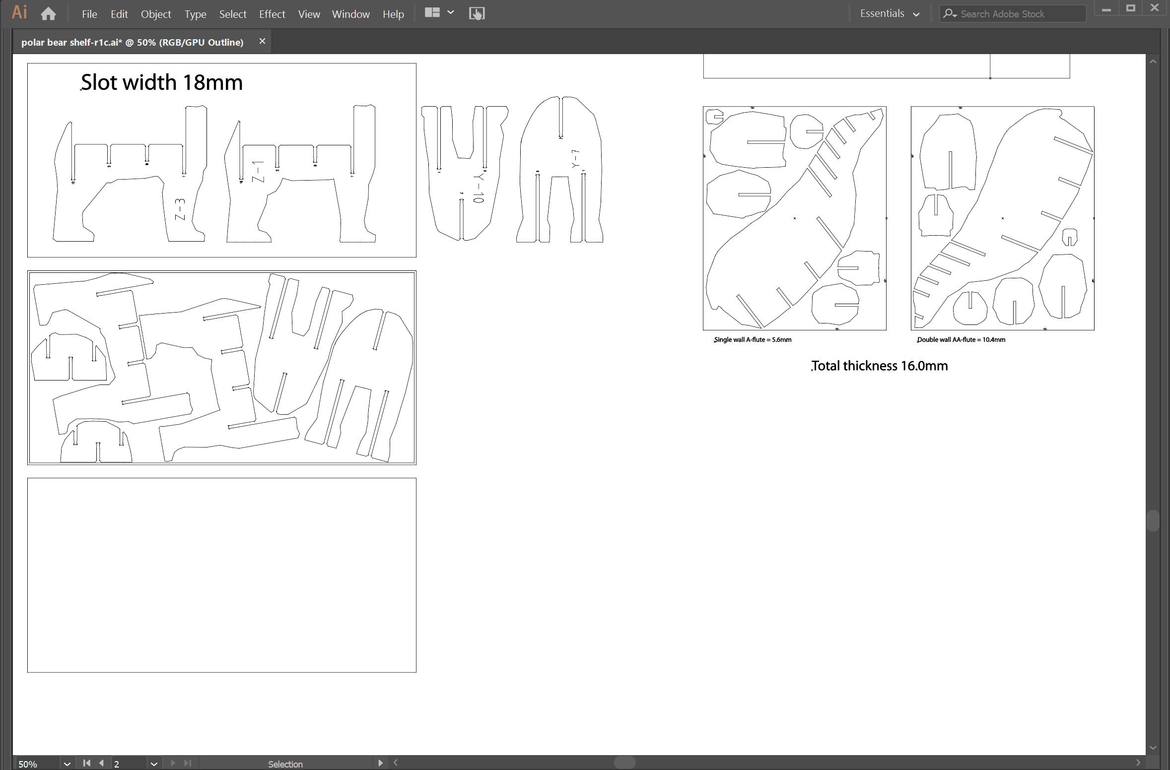
Fitting test on the final plywood of 18mm (17.8mm to be exact)
Practice to change the tool head as one of the common task for using CNC.
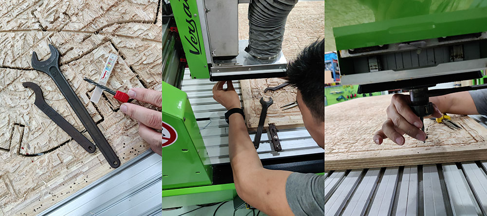
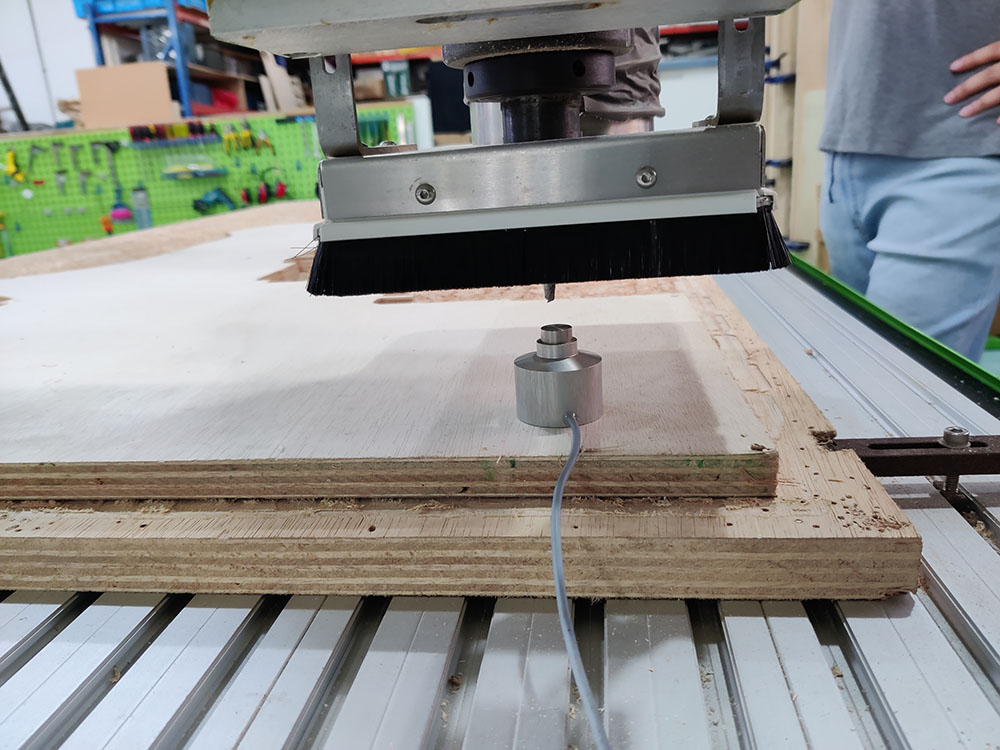
Z-axis calibration using the digital probe for changing material thickness every time.
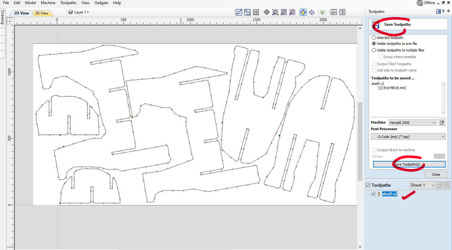
VCarve-Pro: to create G-code for the CAM-toolpath
Once the dxf file is ready, I proceed to the CNC machine computer terminal to load it in VCarve-Pro. I have downloaded the free version of the program but can not save or export the toolpath as it is just for practice until you pay for the full license.
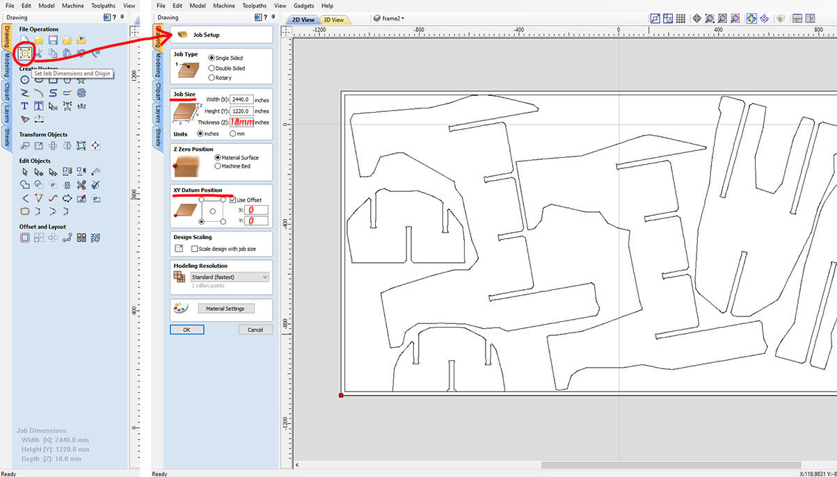
After the file is loaded in Vcarve-Pro, I start to set the size of the material, in this case it is 8 feet by 4 feet (2440 x 1220mm x 18mm). 18mm is the thickness of the plywood I chose for my assignment.
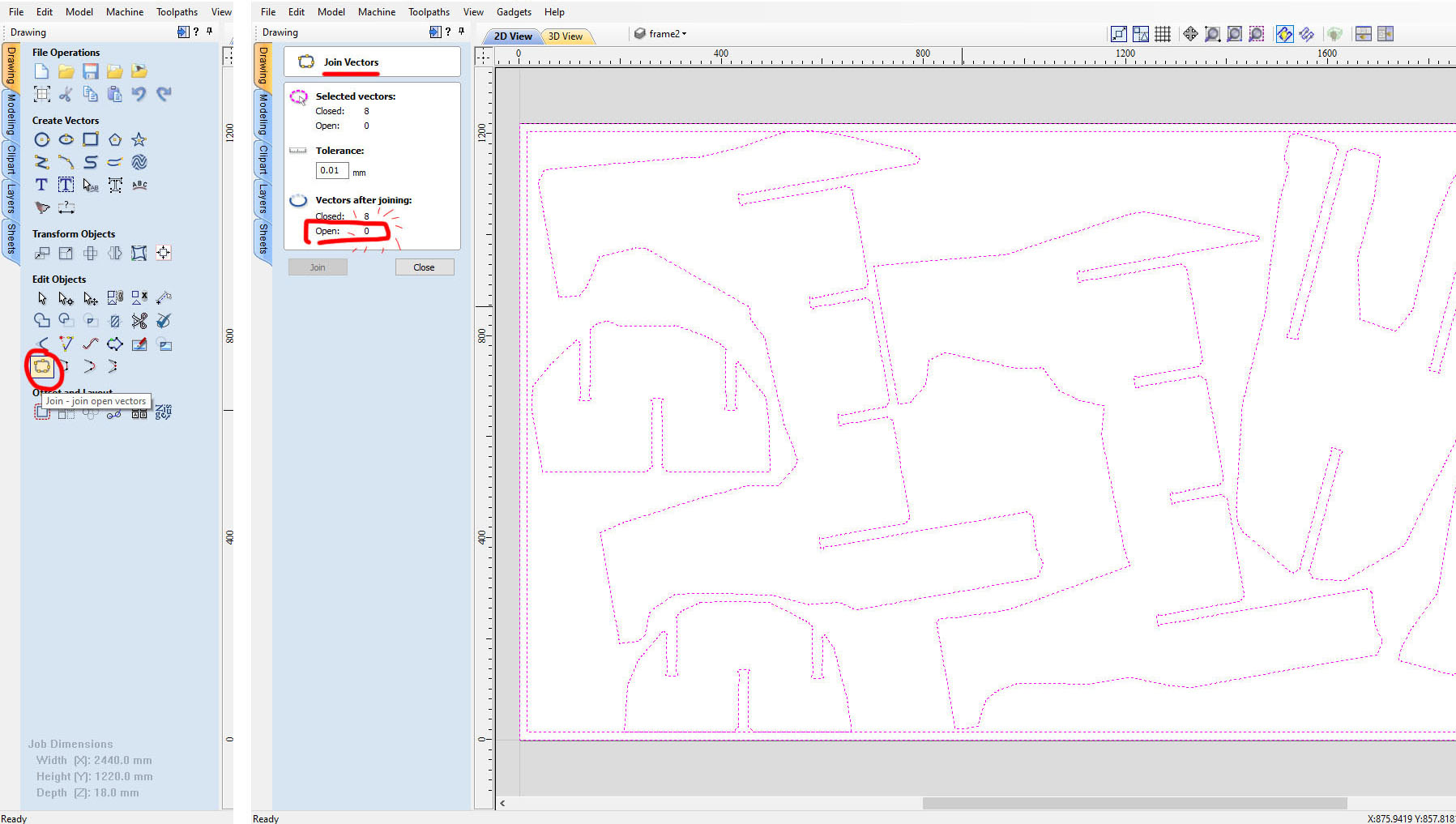
I clicked on the button to close all the lines, if they are not closed we can not generate the milling path. To do so we select all the polylines and click on the Joint tab, if there are open corners the program tells us and we accept to close them.
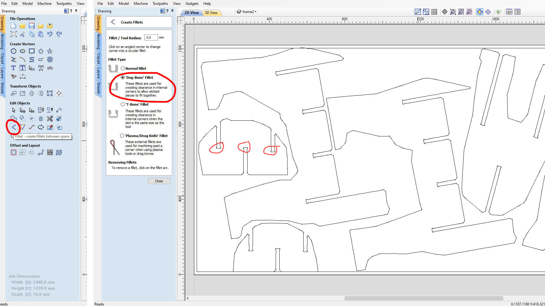
After the pieces are milled, they need to be fit together and it is better to have all the corners rounded inside. I have previously done the dog bone in Adobe Illustrator. But somehow I like to document this step for future reference. To do so we click in the tab Create fillets -> Dog-Bone Fillet, and select all the corners to convert to the Dog-Bone fillet.
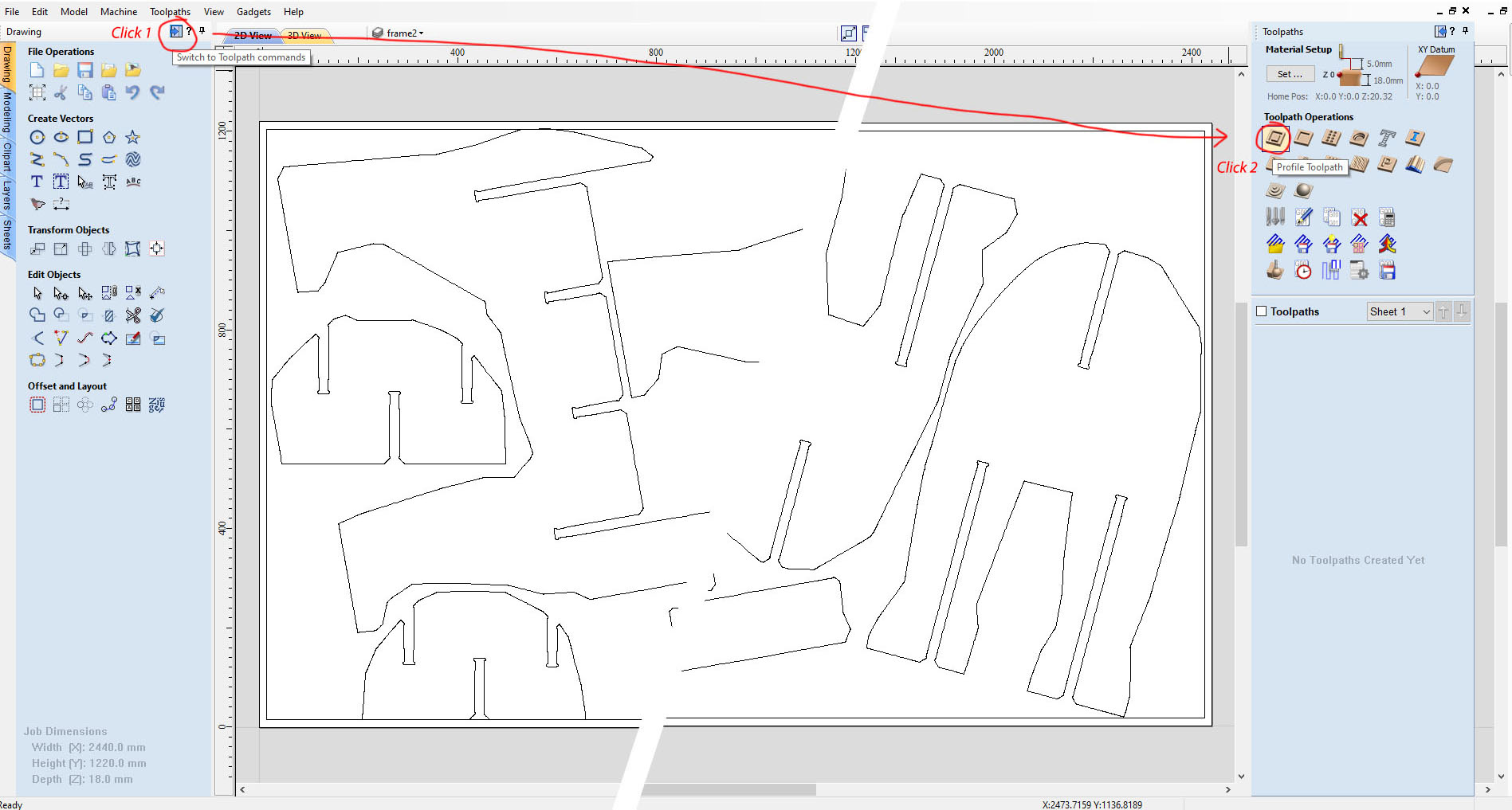
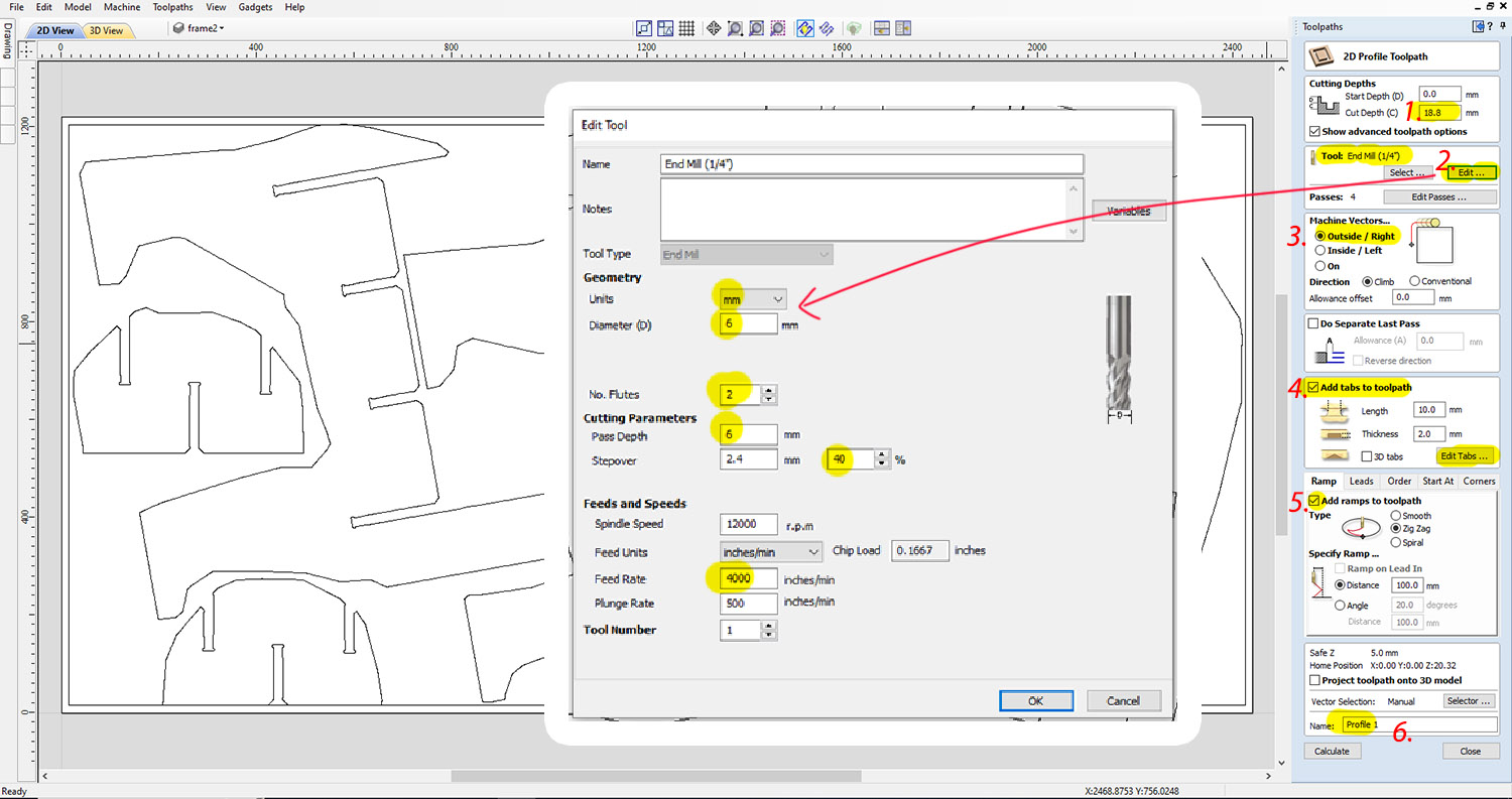
At this point the 2D settings are ready, so moving on to Toolpath Commands. In this window I set the machine's way of doing the mill and the characteristics. I select the 2D Profile Toolpath, which is for cutting through the material settings.
At the 2D Profile Toolpath window, we have to select several options:
- Depth of the board, in my case 18mm we add 5mm in case the material is bended
- Tool: End mill we choose Edit
- Machine Vectors, we select Outside so we don't lose material at the borders while milling.
- Add tabs to toolpath, we select Edit tabs
- Add ramps, we select it and choose zig zag with a distance of 12.5mm
- We name the profile to save later and Click on Calculate.
For the Tool End mill, choose the following settings:
- Units mm
- The diameter of the End mill is 6mm
- No of flutes is 2
- The pass depth of the radius of the mill is 6mm
- Stepover of 40%
- I just changed the Feed Rate to 4000
- With these feeds and speed, we have a chip load of 0.1667 within the recommended range of 0.025-0.25mm
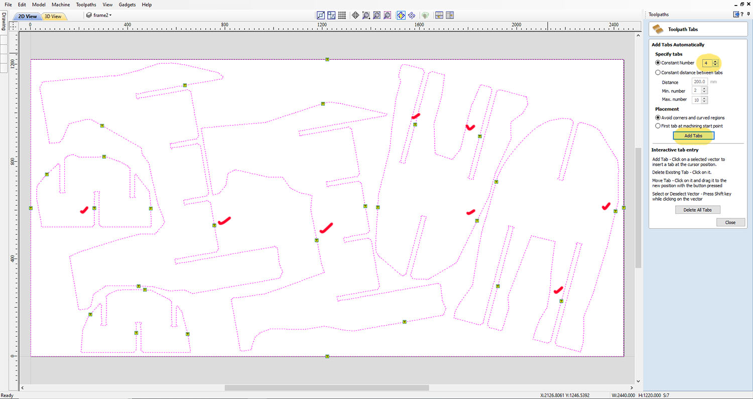
The addition of the Tabs at the toolpath is very important, as the milling is in the process the pieces can get loose and could be thrown off by accident and hurt the user or someone nearby.
The exceptional case for above is any small holes that would NOT generate leftover pieces. The program has the option to locate the 4 tabs by default, or we can locate them manually or edit their position in the drawing by clicking on the points.
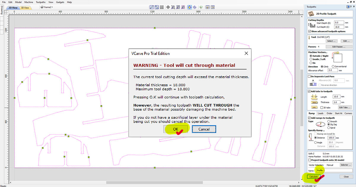
As all the Toolpaths settings are ready we hit calculate, the program will give warning if the cutting is too deep for the bed. However, our machine has a “Sacrificial Layer (of plywood)” which is a piece of plywood that will protect the bed and will guarantee the mill cut through our material in the case it is warp. Click "OK" to proceed.
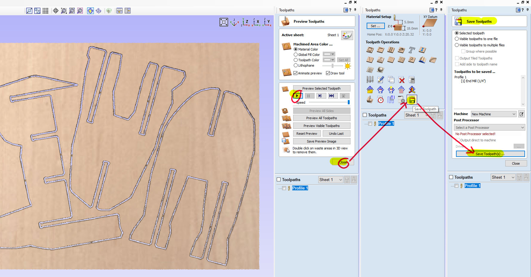
The program comes to a window of Preview Toolpaths, where simulated animation show up at the preset speed.
Next, save the toolpath into a G-Code file and send to the CNC Program printer- NC-EAS(Y) Pro.
NC-EAS(Y) Pro
Before cutting we set the spindle positioning (origin for X-axis and Y-axis, making the whole cutting fit into the material sheets) and the material thickness (probe calibration).
Always remember to turn on the chip wood vacuum suction and before milling (and turn it off after). Always has the controller in hand just in case for the emergency button.
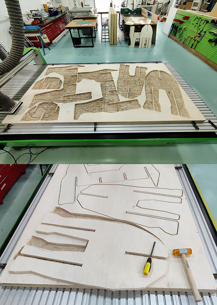
Click on the following photo for more behind-the-scene album.
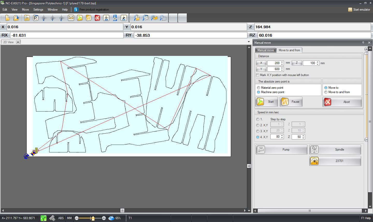
Spent 2 hours and 15 mins for milling 2440mm x 1220mm plywood with my design.
Challenges for project
Having previous experience in operating other machine like the Jwei flatbed cutting machine does give me some confident. While I find there are more setting in tool heads to get the job done, practice frequently is the only way forward.
As with any other week of assignment, the week passed by quickly and we always hope there are more time to do more. In my case, I only manage to mill one 18mm plywood (2.4m x 1.2m) and the other parts were replaced with cardboard (brown colour). Maybe one day I will continue to mill the rest of the Polar Bear book shelf.
Hero shot
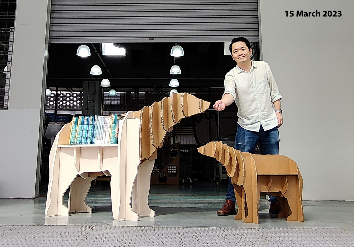
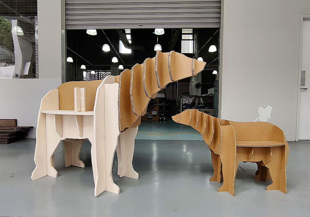
Design Inspiration: CNC animal design. The polar bear bookshelf template is self-created from 3D modelling to actual production and self-assembled.
Download Link
- Polar Bear Bookshelf Blender file - blend format
- Slicer for Polar Bear Bookshelf - 3dmk format
- Adobe illustrator file - ai format
- DXF file