14. Interface and application programming
Group assignment for this week:
- Compare as many tool options as possible
The documentation of group assignment can be found on our group work page.
Individual assignment for this week:
- Write an application that interfaces a user with an input and/or output device(s) on a board that you made
G4P GUI builder in Processing
This is almost the last week of documentation, and it's been over a month since the lectures, so this is almost just a refresher on what it was all about. The topic is completely new to me and my coding skills are at a very early stage, so I can't take my understanding very far in this time... In this assignment I will use the board which was designed in week 6 and made in week 8.
My intention is to try testing with the G4P GUI builder tool in Processing. Processing is a flexible software sketchbook and a language for learning how to code. Its free and open-source software. Contributors share programs, contribute code, and build libraries, tools, and modes to extend the possibilities of the software. The Processing community has written more than a hundred libraries for computer vision, data visualization, music composition, networking, 3D file exporting, and programming electronics.
I will start with an example made by our instructor to help me remember the whole tool. With the G4P GUI builder tool, it is possible to build an interface with different controls, for example a button, slider, textfield, etc. When you make changes in the GUI builder tool, the code for each controls is created in the gui file.
For a serial communication connection, you always need to import the processing.serial library:

Create object from Serial class:

And open the port in void setup():

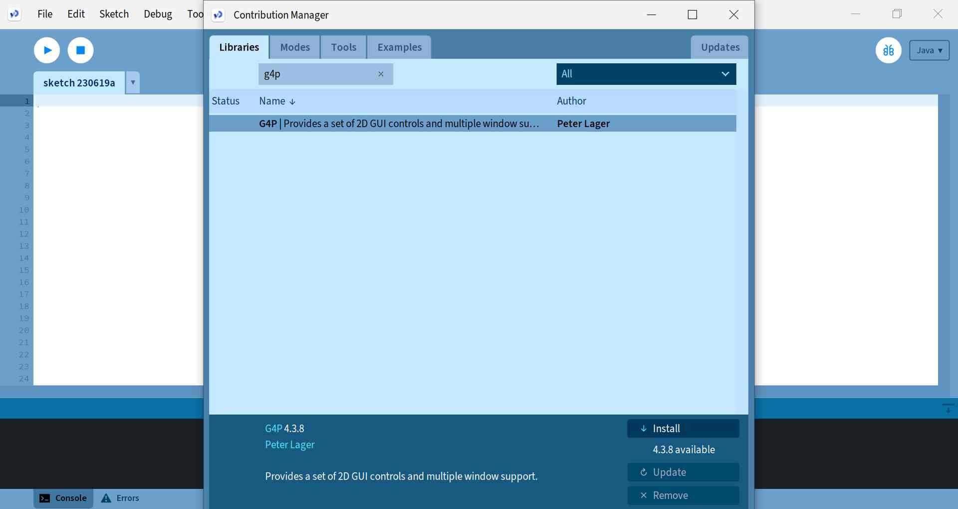
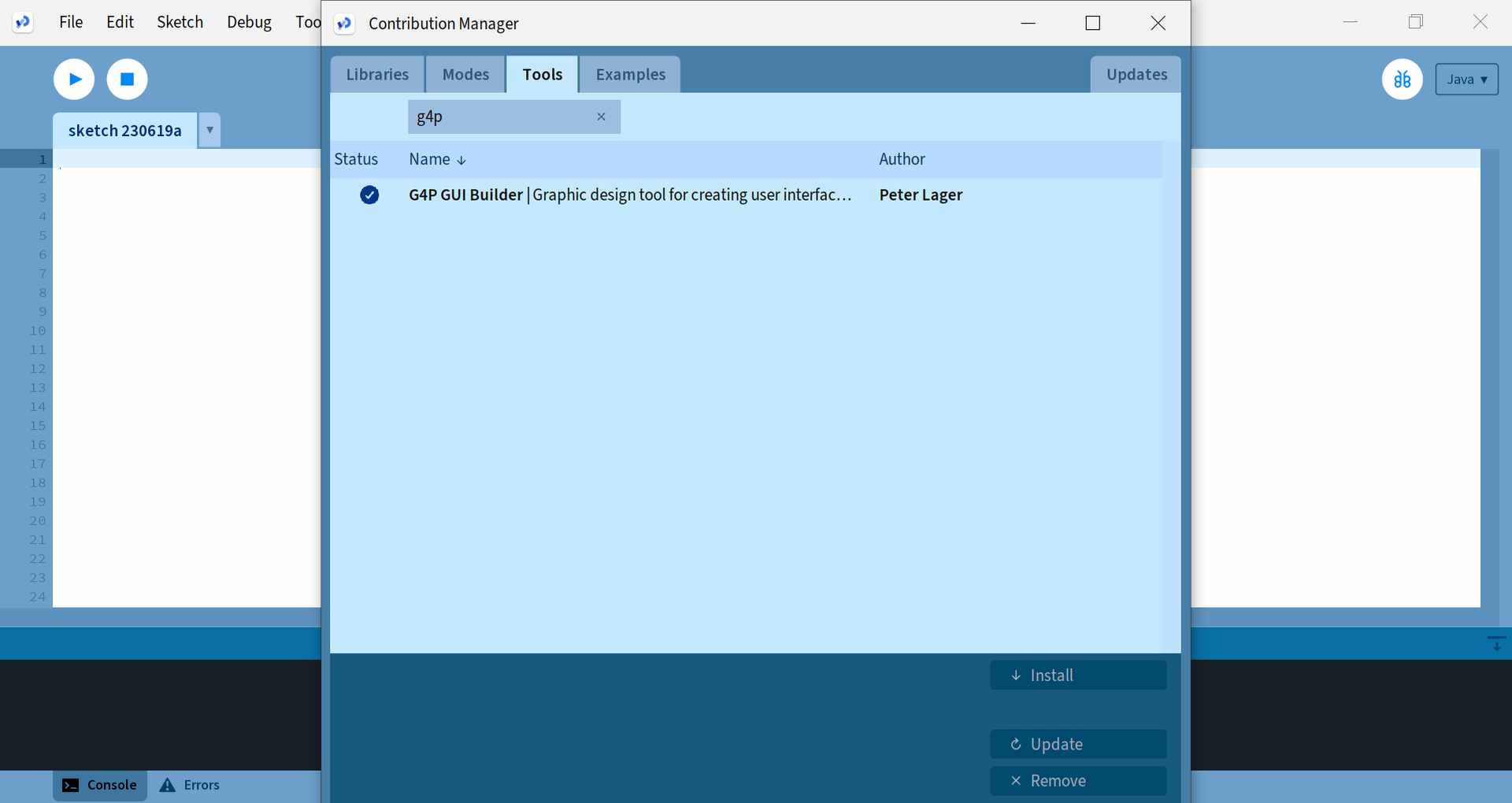
To start working with the G4P GUI builder, first you need to download the tool and the library for it. From the Sketch menu, open "Import Library..." and "Manage Libraries". Search for g4p to find the right library and install it. In the same window, there is also a Tools tab where you can search for the right tool using the g4p search term. Pictures below.
|
|
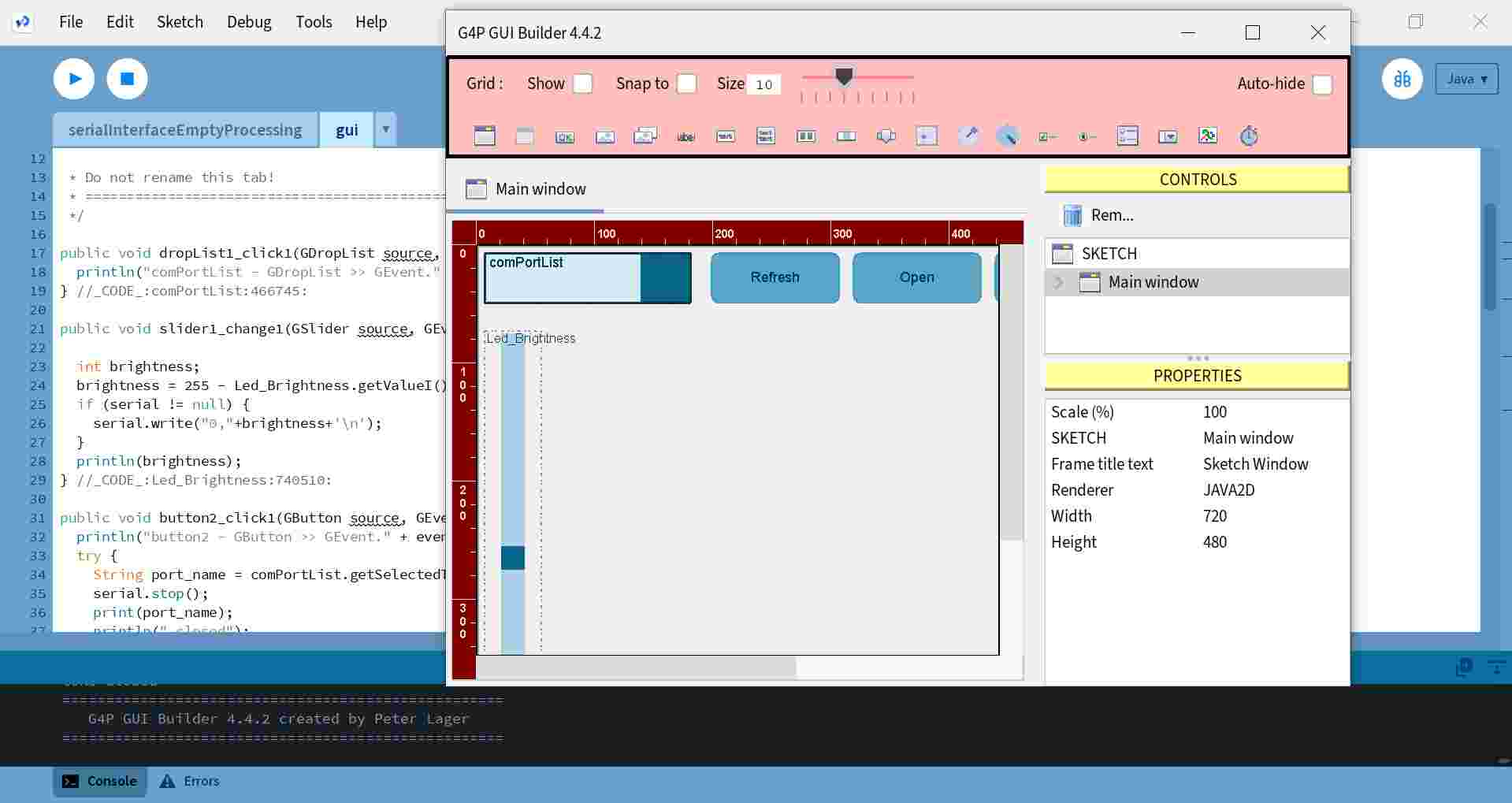
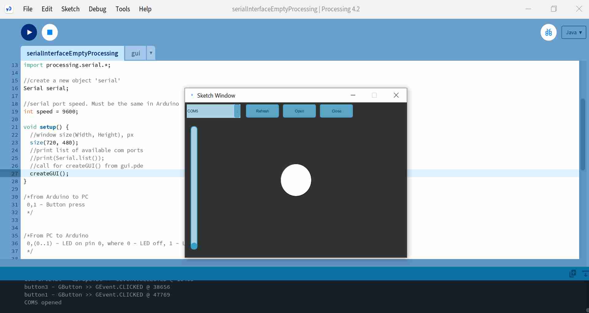
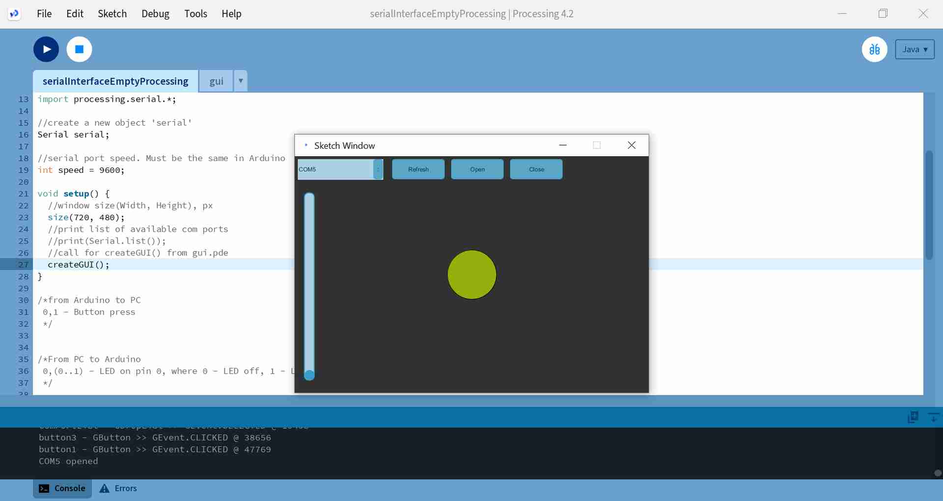
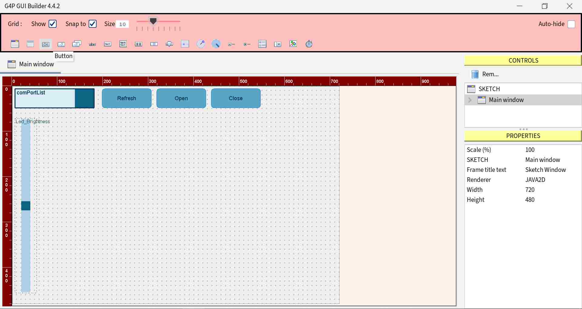
Next, I opened the files of the example made by our instructor. I uploaded the arduino IDE code from the example folder to my board. In this example it is possible to find the right port, open and close the serial port communication, adjust the intensity of the LED on the board with a slider and press a button on the board to randomly change the colour of the circle. Below left is the view in the GUI builder and on the right the view in the Sketch Window after running the code.
|
|
The picture below shows when a button has been pressed on a board and the colour of the circle has changed randomly.
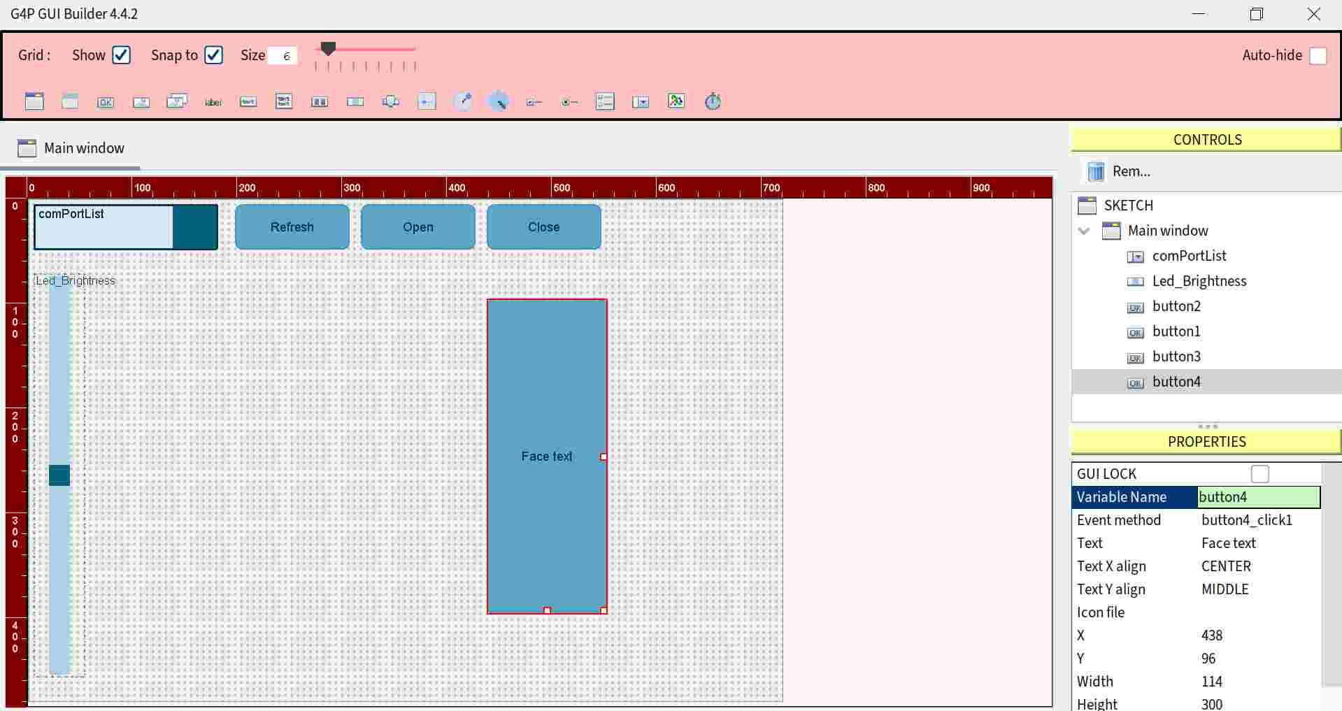
Next, I tested adding my own button in the GUI builder. My intention was to make a button in the application to turn on and off the LED on my circuit board. I selected a Button from the top menu icons, increased the button size and moved the rectangular button to the right edge of the area. Pictures below.
|
|
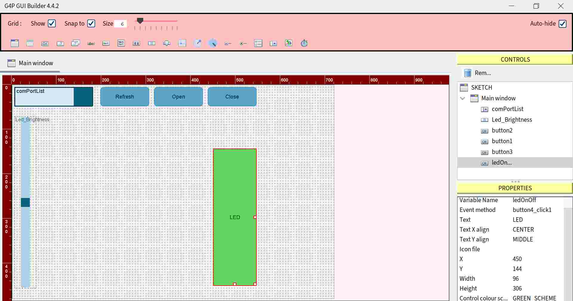
When I clicked button4 from the right menu, I could change the button properties, for example the variable name, which I named ledOnOff. I also changed the button text to LED and changed the colour scheme to green. Picture below left.
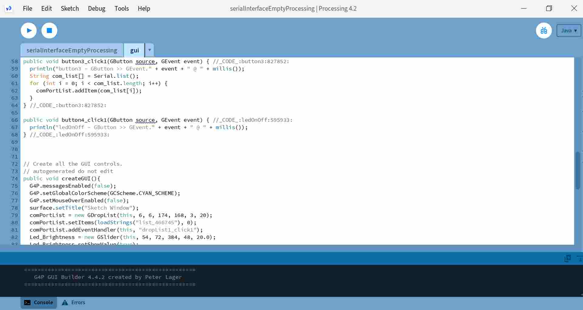
I closed the GUI builder and while I had edited a new button in the GUI builder, the code for the button was also automatically created in the gui file. Picture below right.
|
|
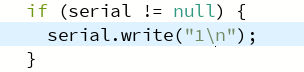
The button4 code did not yet have a communication link to serial, so the basis for the button communication was copied from the slider code and the serial.write was changed to "1\n". I added the lines in the picture below to the gui file under public void button4_click1, which is an event handler for the button press event. The code was then able to turn the LED on or off.
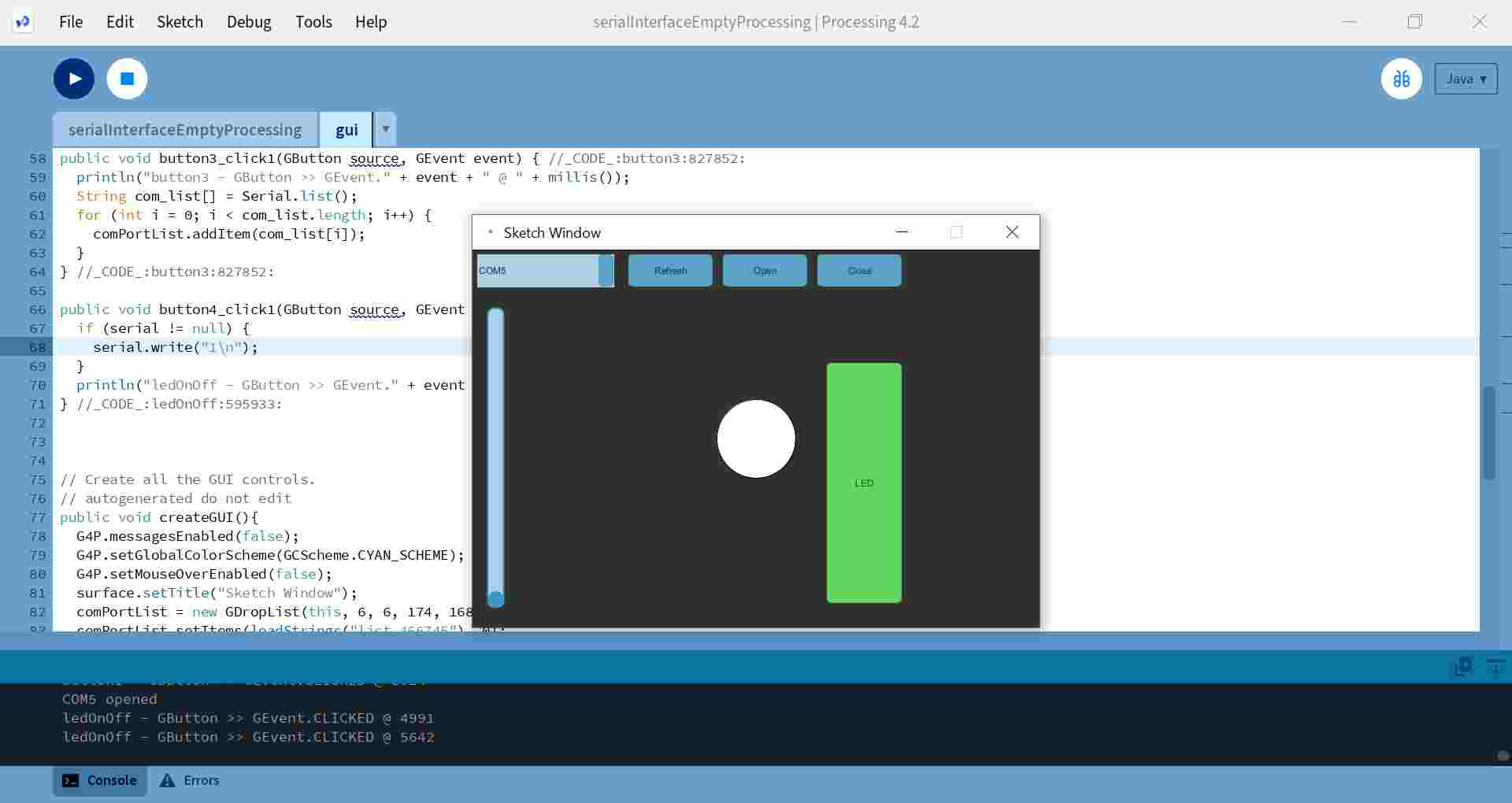
Below is the view in the Sketch Window when the code is run and by pressing the LED button the LED on the board can be turned on and off.
This was a very interesting example test and the next thing I started thinking about what I could do next. And what I could do with my skills, since my coding skills are very poor. I was able to use the DHT22 sensor that I had tested in Input devices week. I wondered if I could get its values displayed in a textfield created in the GUI builder...
I tried to find examples of how this could be done, but at the time I couldn't really find anything other than examples of how to display the readings from the temperature sensor in a view created with the Meter library.
Then I found examples of how Iván Sánches Milara and Heidi Hartikainen had tested a ultrasonic sensor module and got its readings to appear in a textfield created with the GUI builder.
I thought I'd try to find some kind of solution by combining experiences here and there, but it just doesn't work, surprisingly. :D And when you don't understand, it's hard to try to find the missing pieces. I won't even start to write here what I tried, because I got so frustrated that I threw all the experimentation in the trash.
I wondered why I had to do this when I feel I don't understand how to write code at the moment. The hard spring became concrete after the final project presentation and I felt that I couldn't learn anything more at the moment.
I decided to take a break and try again for another moment. I met one of my friends and we talked about these studies and the painful progress of the last assignments. She asked me if I had tried to ask ChatGPT for help and I just thought, I haven't. So the next time a couple of days later when I was ready to face this week again, I created my ChatGPT account and started experimenting.
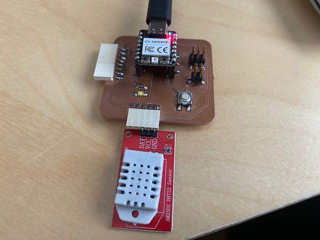
First I connected the AM2302/DHT22 temperature and humidity sensor to my board. I was able to connect the sensor directly to the male connector on the board I made in week 8. The pins to connect were VCC, Ground and Data. The Data pin was connected to pin D4. This DHT22 has a pullup already inside. The setup is in the picture below.
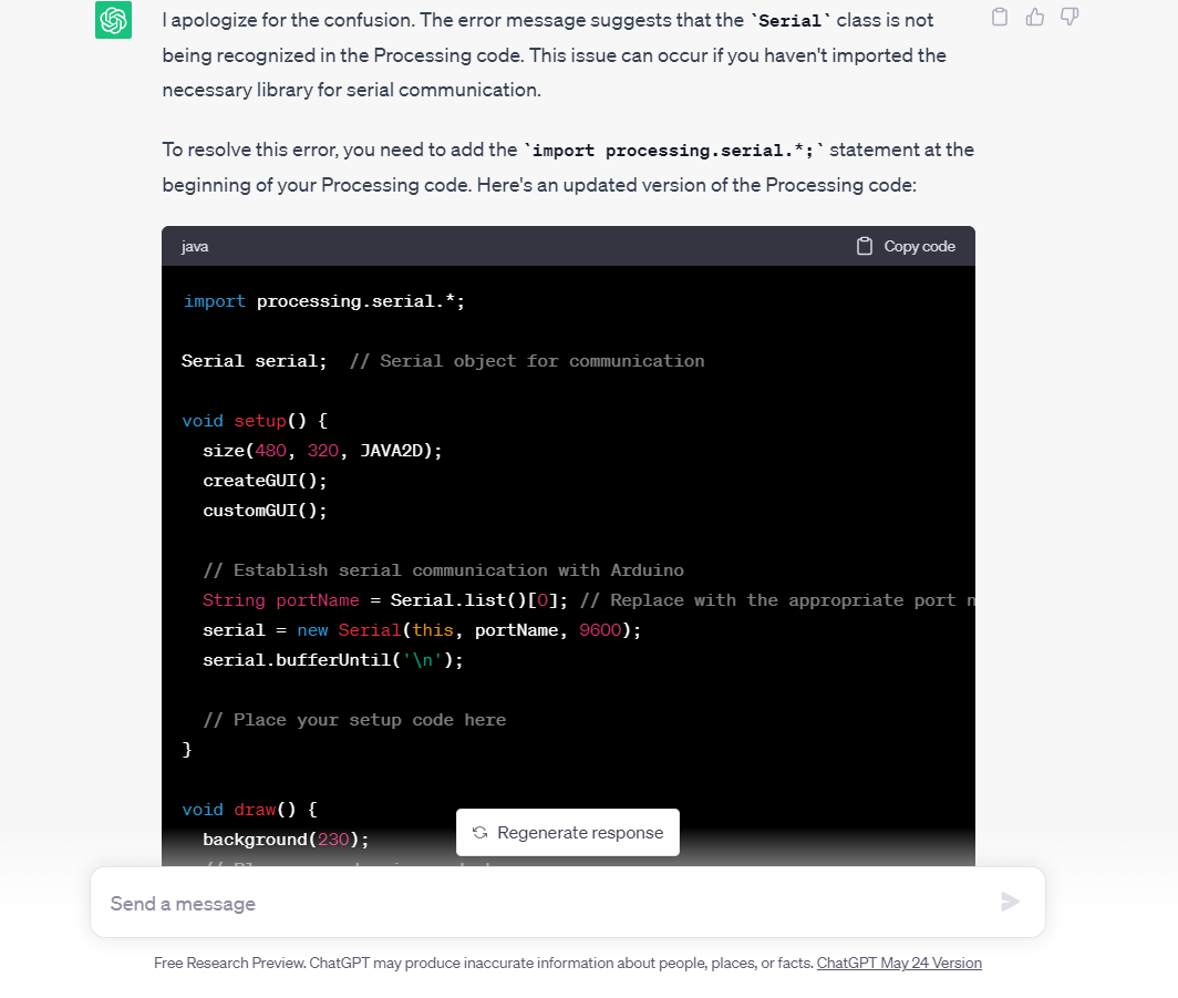
I told ChatGPT that I was using the G4P GUI builder tool in Processing and wanted to display temperature values from the DHT22 sensor in a textfield created in the GUI builder. I asked it to generate the codes for me in both Arduino Ide and Processing. I was quite skeptical at first that this was going to be the same kind of frustration cycle I had before, as I tried desperately to combine a bit of this and that.
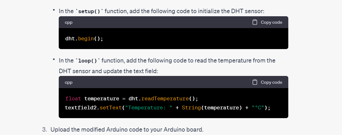
I got the answer shown in the pictures below:
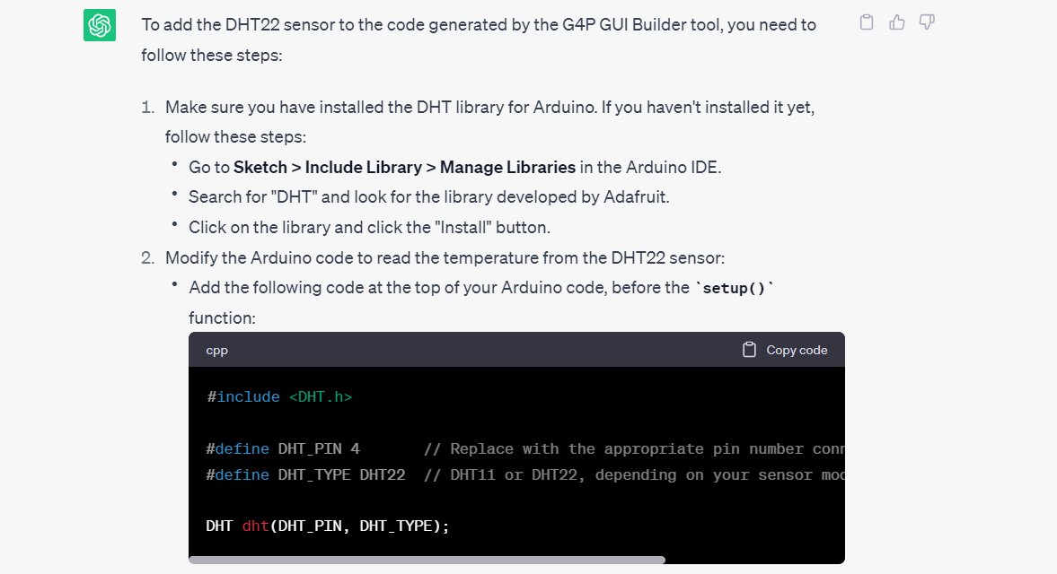
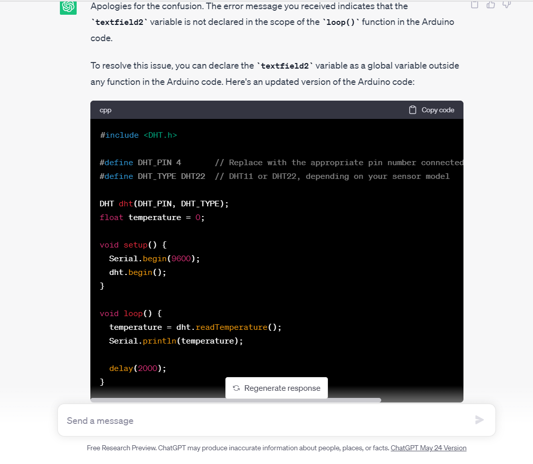
I just decided to start testing. I first copied the code to the Arduino IDE and got the error message:
Compilation error: 'textfield2' was not declared in this scope.
I asked ChatGPT what I should change in the code. It gave me the updated code below, I copied it to the Arduino IDE, defined the DHT pin to D4 and uploaded the code to the board. It worked. I got the temperature values displayed on the serial monitor.
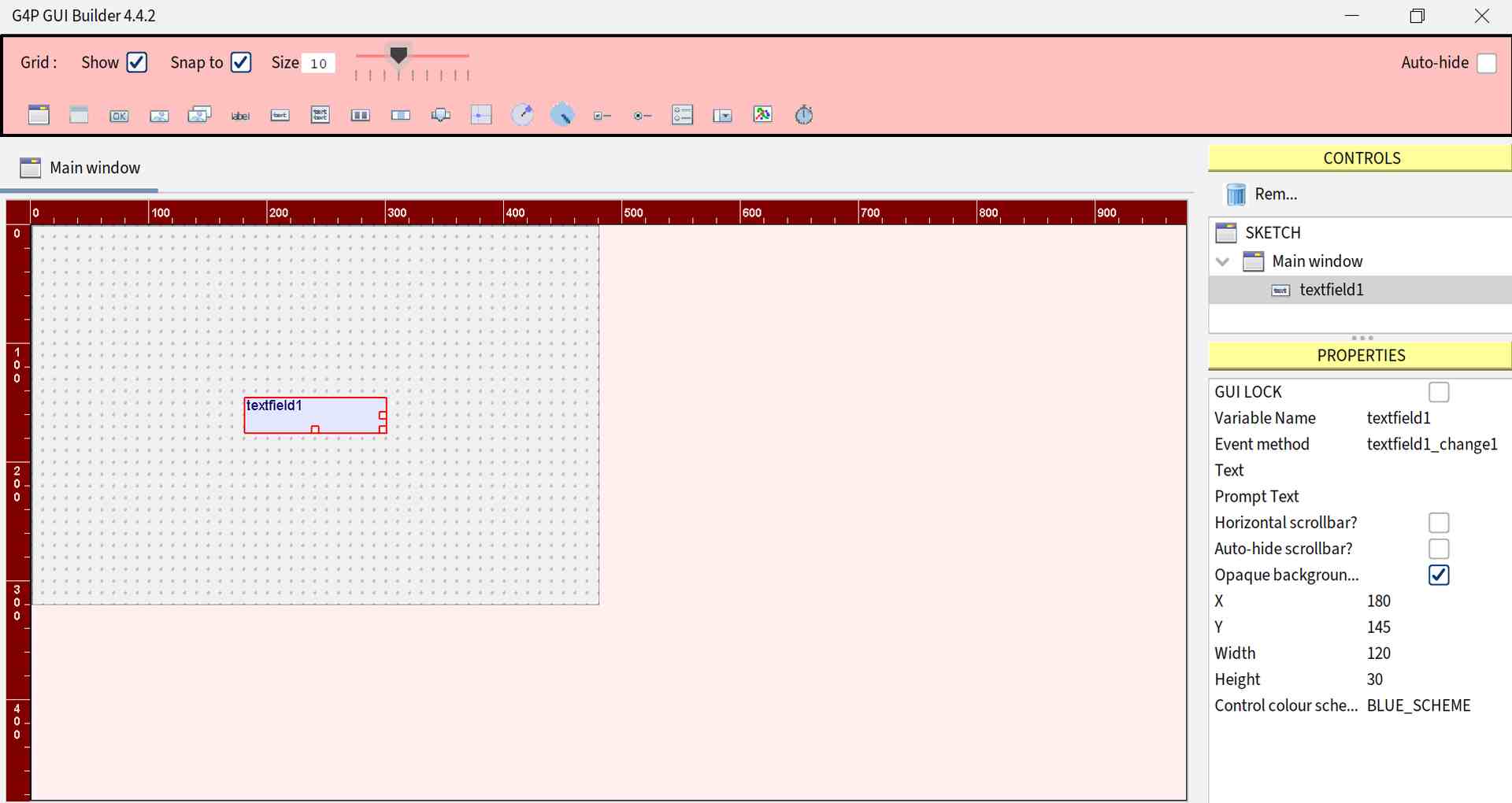
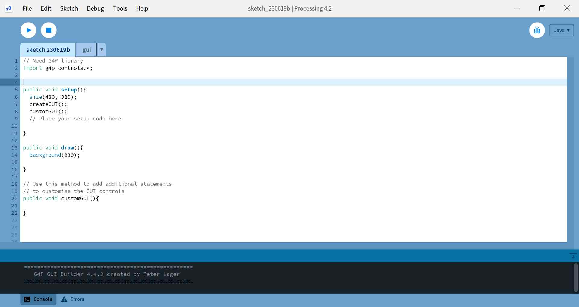
Next, in Processing I opened New file from File menu and then opened the G4P GUI builder tool from Tools menu. I added a textfield to the area. Picture below. Later I renamed this to textfield2, because I messed up with the tests and later in the code had textfield2, so I matched this with the GUI builder.
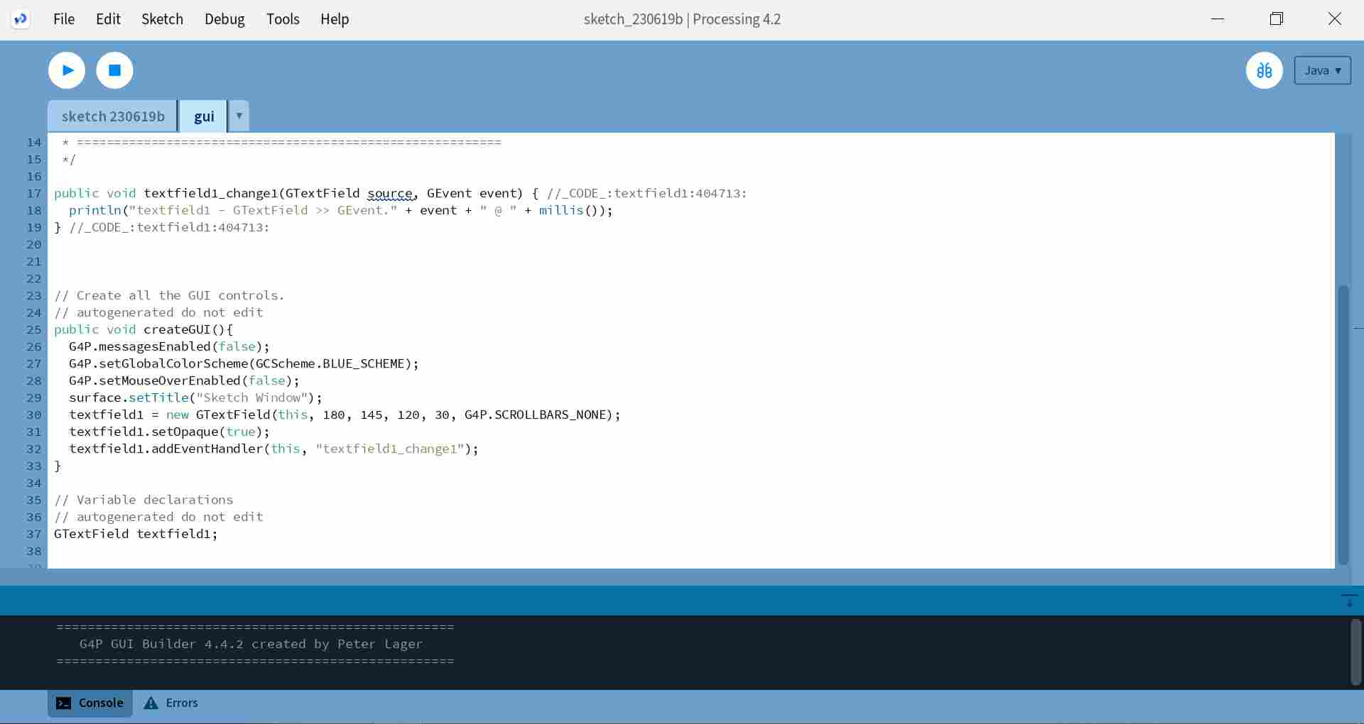
Below are the codes that were created into the files when I added the textfield in the GUI builder.
|
|
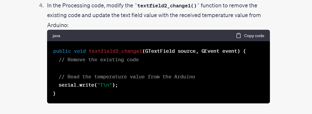
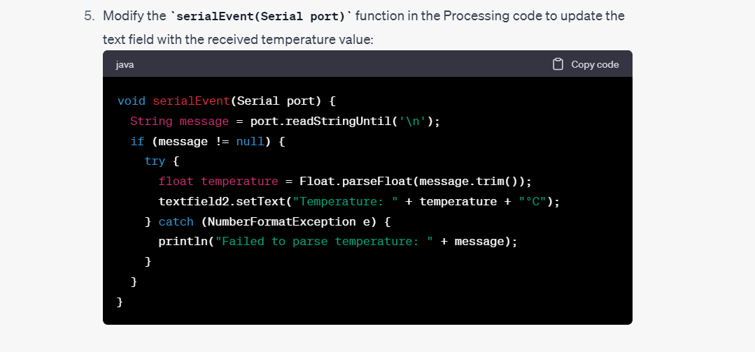
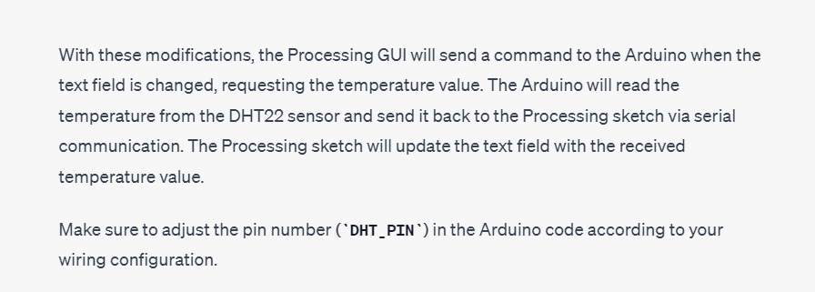
I modified the code with the additions made by ChatGPT, I added point 4 of the instructions to the gui file and point 5 to the end of the other file.
When I ran the code, processing gave me an error message:
Cannot find a class or type named “Serial”
I noticed myself that the serial communication library was missing, but I asked ChatGPT what it would change in the code. It gave me the fully updated code:
I added the new code to Processing, but also kept the line "import g4p_controls*;" at the top of the code, because that library was also needed.
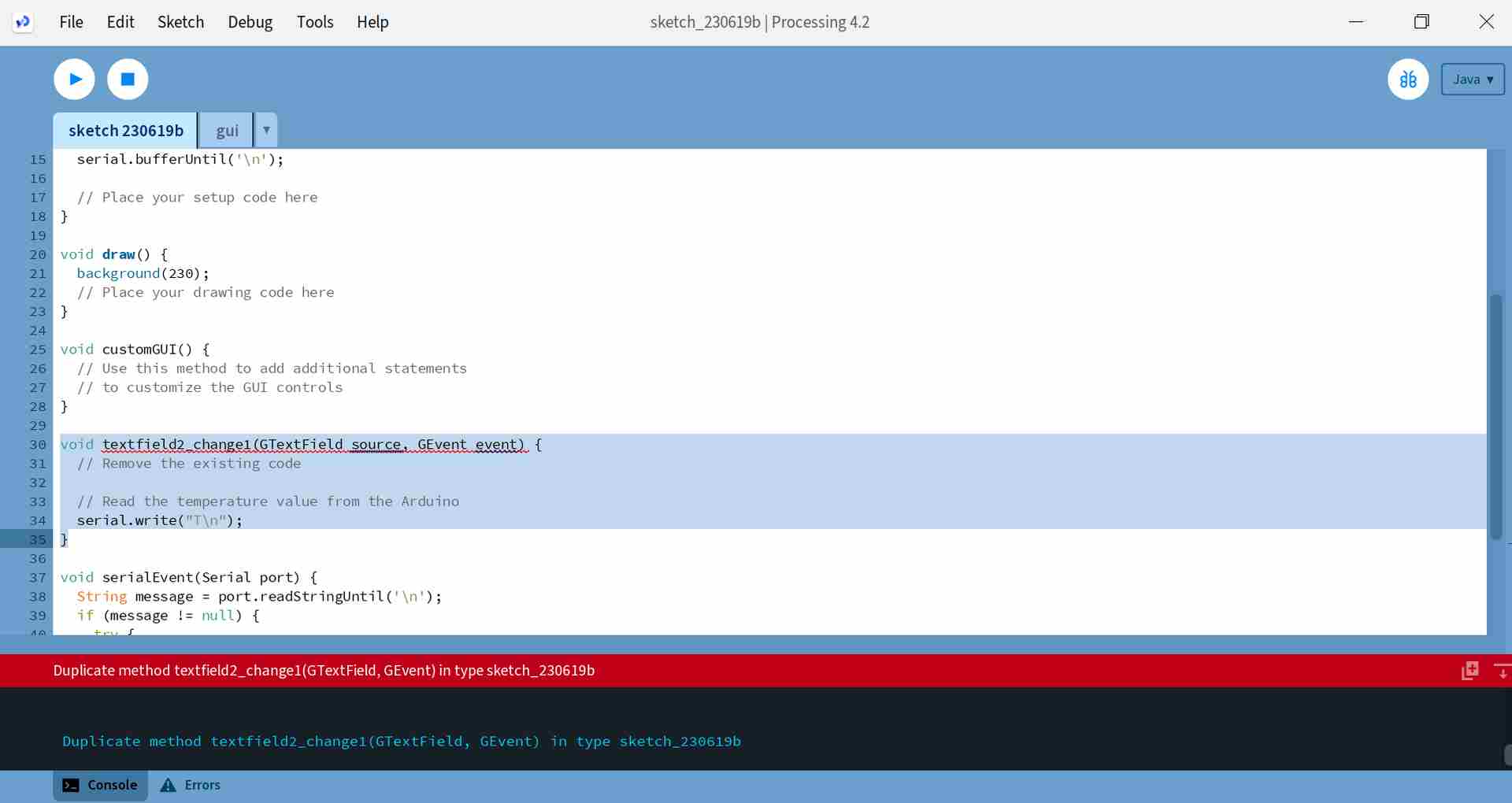
Next I got an error message, which is shown below on the left:
Duplicate method textfiel2_change1(GTextField,GEvent) in type sketch_230619b
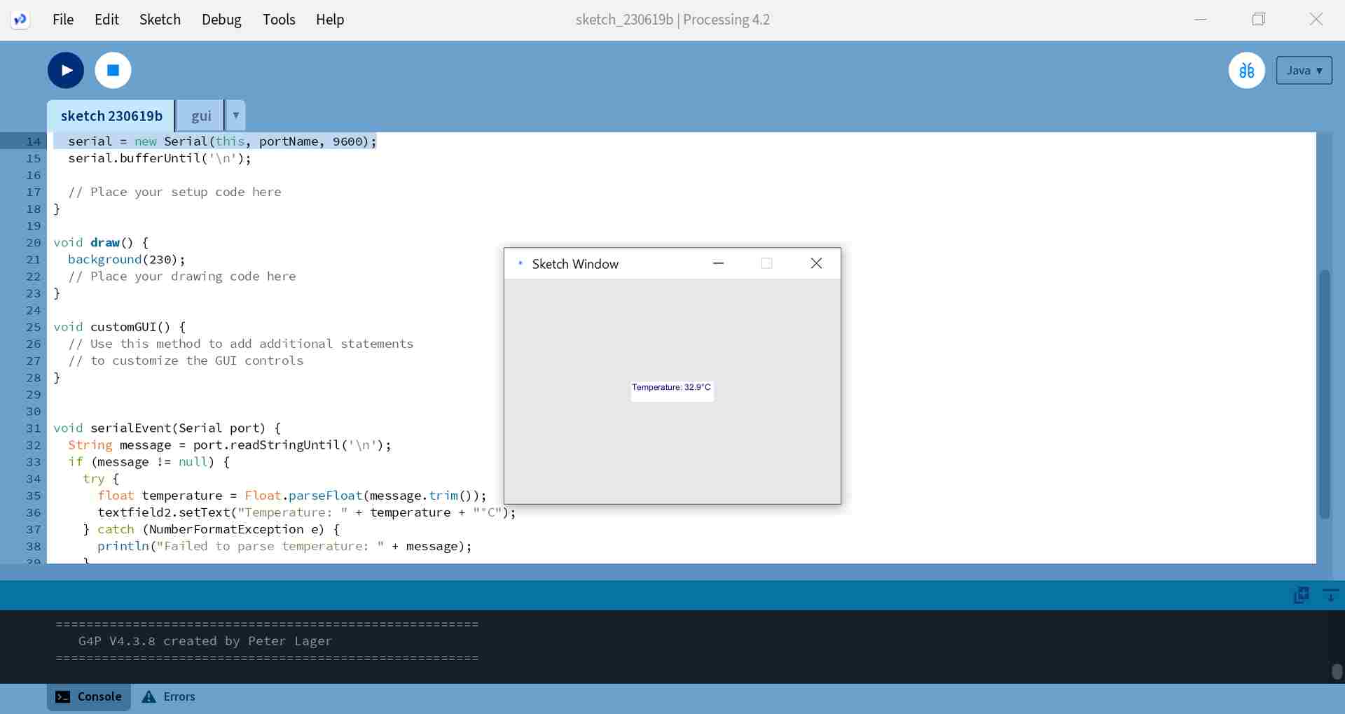
And I decided to edit the code just by removing these lines. I ran the code and it worked! The temperature value was updating in the textfield. Picture below right.
|
|
The video below also shows how the temperature values update when I cool the sensor in front of the fan:
Okay, I had working code and a connection to the serial, so I decided to clean up the code a bit and make some minor changes. I removed the parts of the code related to customGUI, because I didn't want to do any customization with it. I resized the window to 300 x 300. I also changed the serial connection code so that the connection is directly through port COM5. I changed the background color of the window. And finally, I changed the text in the textfield so that only the temperature value is updated, followed by "°C".
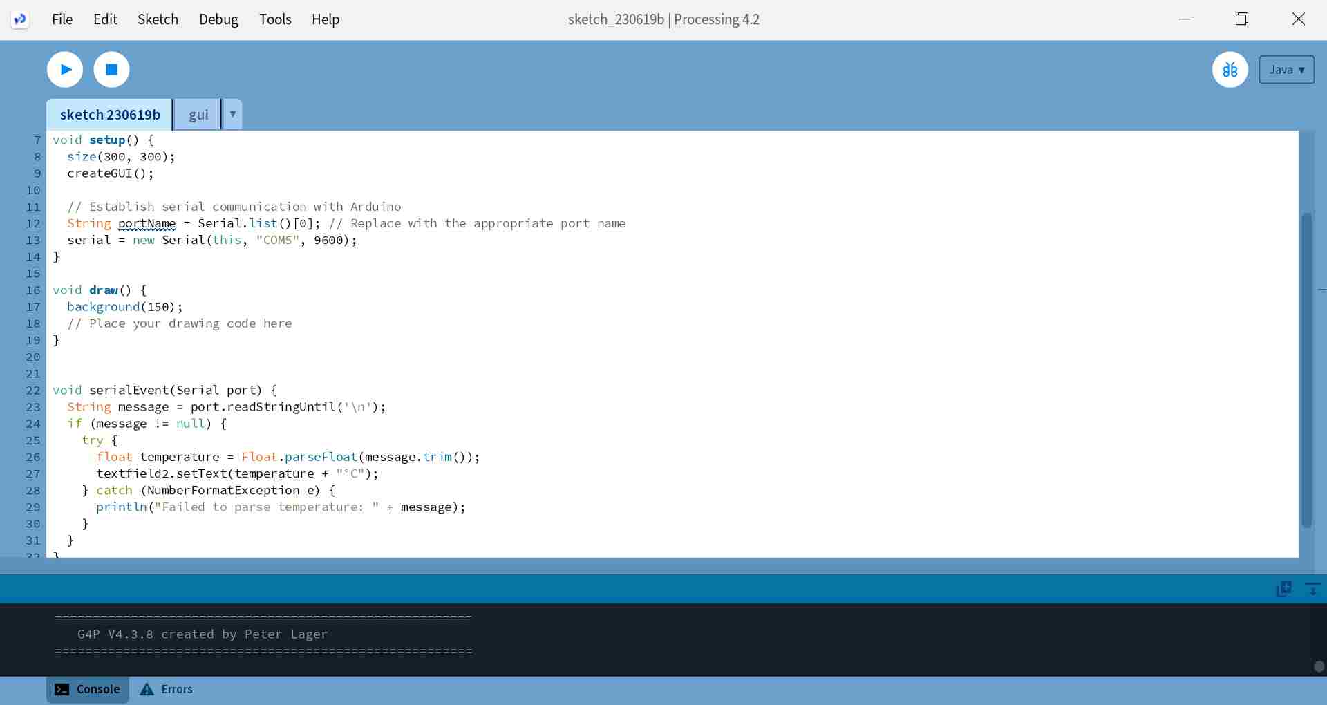
Below left you can see almost all the code, only the first lines about importing libraries and creating a serial object are missing. The whole code is in the downloads below. At the end of the code, in void serialEvent (Serial port), a connection is made to the serial port: Processing receives temperature data from the serial port, parses it as a float, and updates a textfield (textfield2) with the temperature value followed by the "°C".
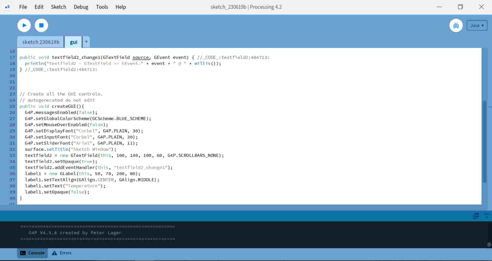
When I looked at the gui code, it had at some point returned to its initial form, picture below right. But the connection to the serial was now on the sketch code and the connection worked.
|
|
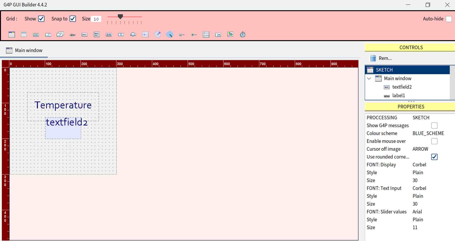
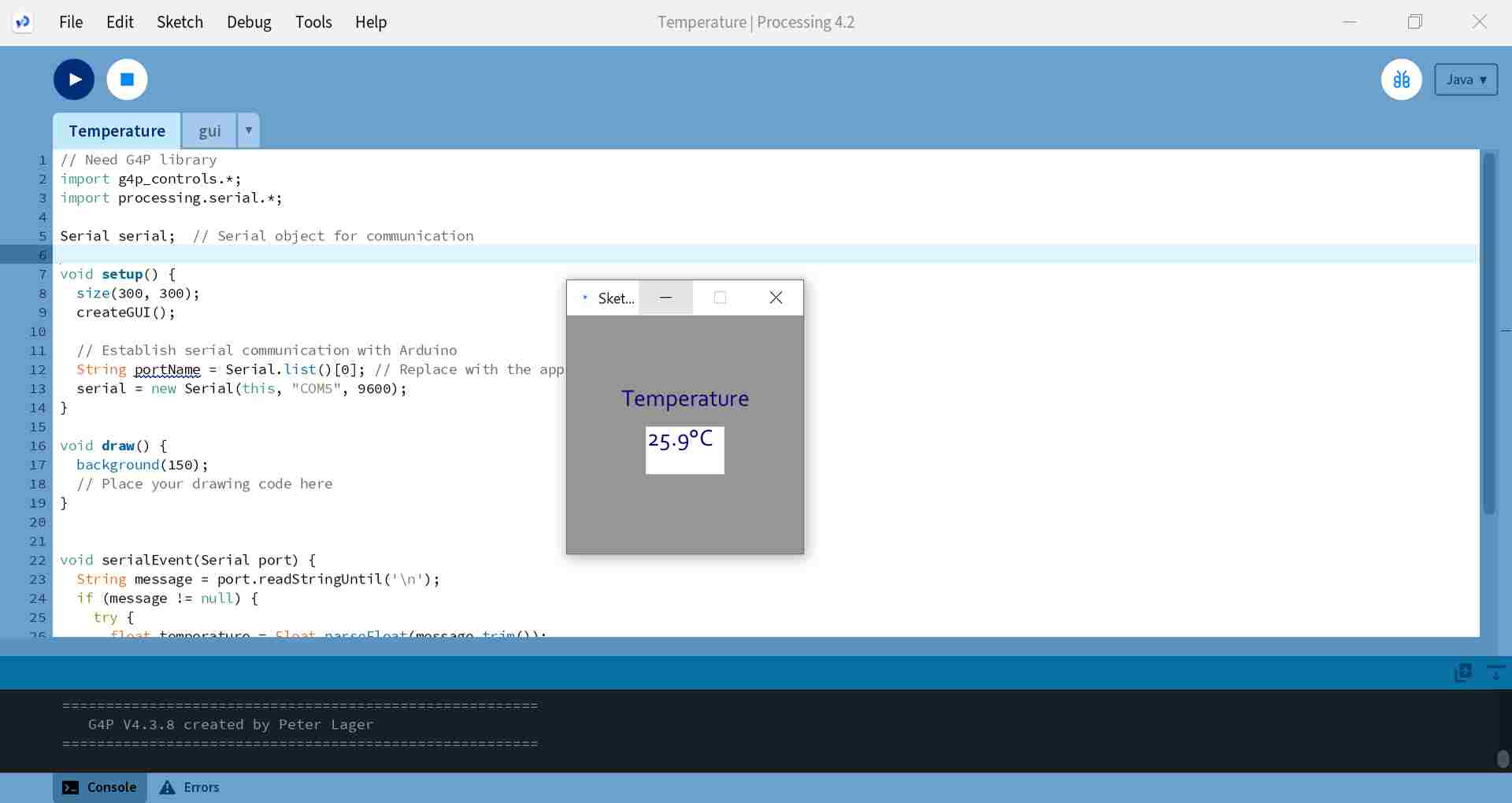
In the end, I edited the view in the GUI builder. I added a label to the area where I wrote Temperature and adjusted the size of the box. I also adjusted the size of the textfield. In the Sketch properties I was able to edit the font and font size. View in GUI builder below left and view in Sketch Window below right. Yay, thanks to ChatGPT, I got at least some working code!
|
|
Download LEDbutton codes .zip folder (based on GllBhh serialInterfaceEmptyProcessing example)