11. Input devices
Group assignment for this week:
- Probe an input device(s)'s analog and digital signals
The documentation of group assignment can be found on our group work page.
In group work we probed digital and analog sensor with oscilloscope to see the output signals. As an analog sensor we used an photoresistor LDR and measured signals when the sensor was freely on the table, when it was covered with a hand and when we used a LED light to flash the sensor. As a digital sensor we used a distance sensor VL53 L1X and from reading we could see the effect of the pull-up resistor, causing the sloping rising signal.
This was an interesting exercise with an oscilloscope that I am not very familiar with. There has been a lot of new things to learn in these electronics lessons, though it will take more than Fab Academy to really internalize what I have learned.
Individual assignment for this week:
- Measure something: add a sensor to a microcontroller board that you have designed and read it
Acceleration sensor ADXL343
At the beginning of this week, I didn't really know what input device to use, because for the final project I had only planned to use the push button as an input device.
When it was my turn to present my documentation and final project to Neil at the global lecture, he recommended measuring motion with an acceleration sensor and maybe developing something from that. I decided to test it first. However, I don't personally find this sensor useful for my final project, but since the sensor is new to me, I wanted to test it.
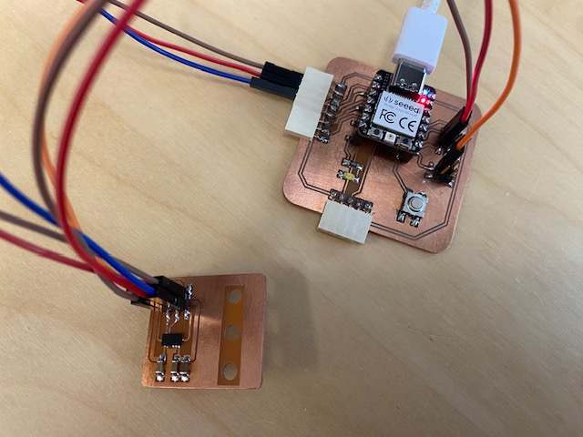
I did not start to make my own board for this sensor right away, instead I borrowed one made by our instructor. The sensor was a 3-axis accelerometer ADXL343. My idea was to first measure what kind of results I get with the sensor and then decide if I wanted to make my own board for further testing.
So I connected the board to my own development board that I had made in week 8. I connected the MISO, MOSI, SCLK, CS, Ground and VCC pins to each other with jump wires. In my own development board, the CS pin was already used for the button, but I was able to connect CS to another digital pin and used the D0 pin. Below you can see the setup.
I got the code from our instructor and changed the pins I used in the code. I also downloaded the Adafruit ADXL343 library in Arduino IDE. The code can be downloaded at the bottom of the page.
Next, I asked my colleague to help me record the test. She took a video of me knitting and took pictures of two different ways I held the ADXL343 sensor while knitting. She also captured screenshots from the computer of the axis values displayed on the serial monitor.
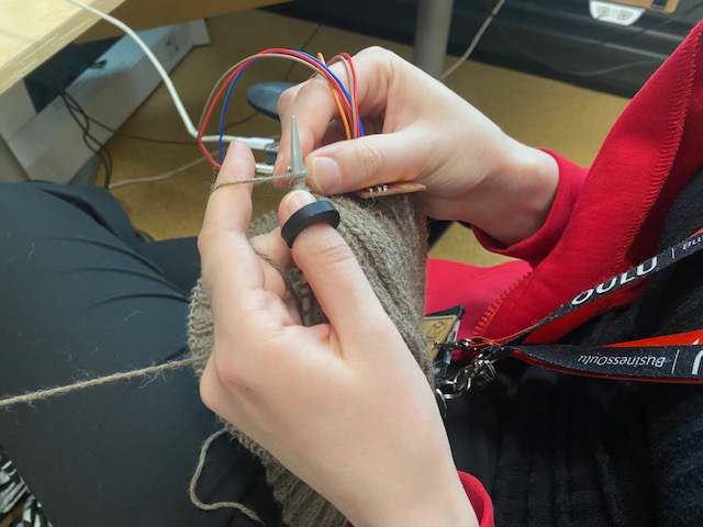
The video below shows my first test, where I held the sensor between my fingers in my right hand, which makes more movement when I knit. You can also see a bit of how my hand moves when I knit.
So I did two tests, one with the sensor between the fingers of my right hand. This was a bit tricky to find a way to keep the sensor with the movement of my right hand. Picture below left. I have also forgotten one of the test rings on my finger, but the ring is not relevant for this test.
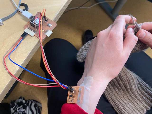
In the second test, I taped the sensor to my left wrist, thinking about the spot where my final project bracelet would possibly be. I tested this because if I would put this sensor on my project, the place would most likely be on my wrist if I didn't want to modify the ring to fit this sensor. Picture below right.
|
|
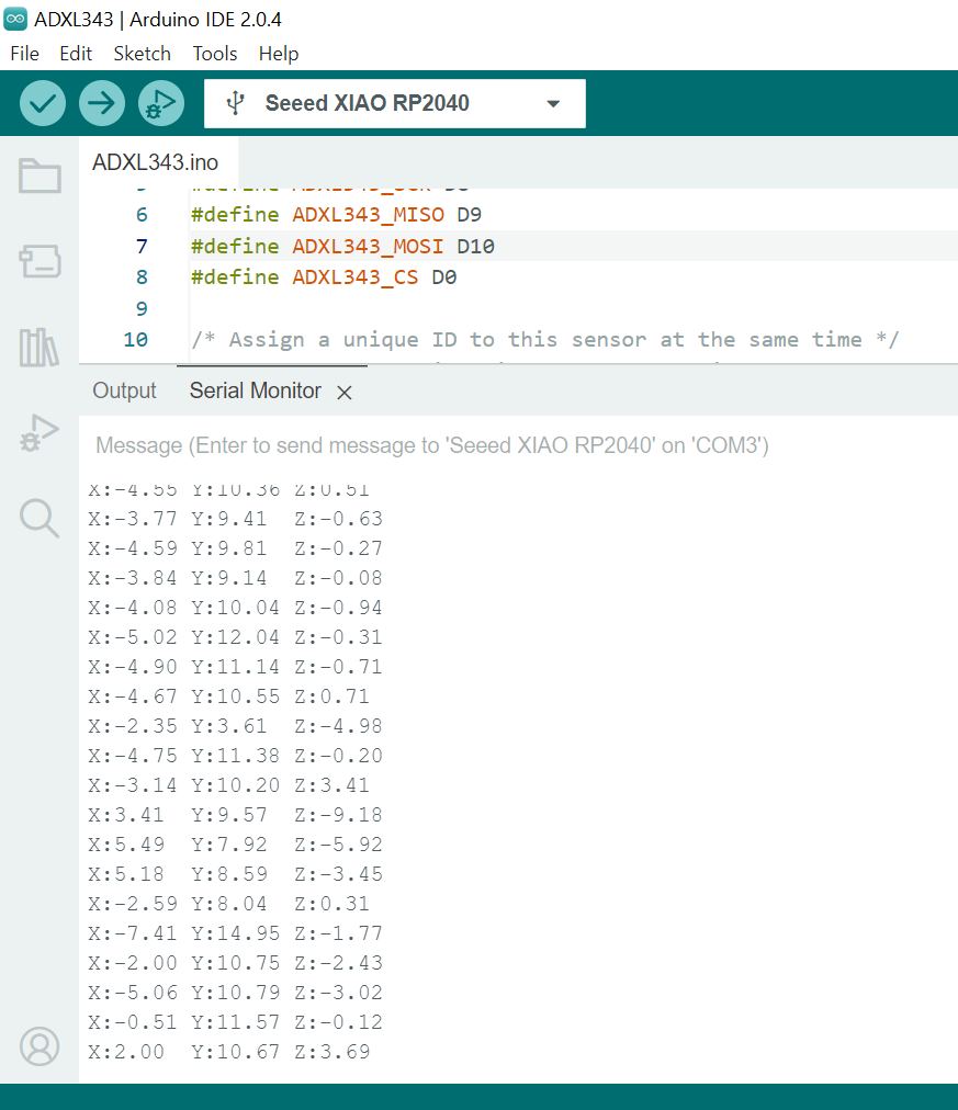
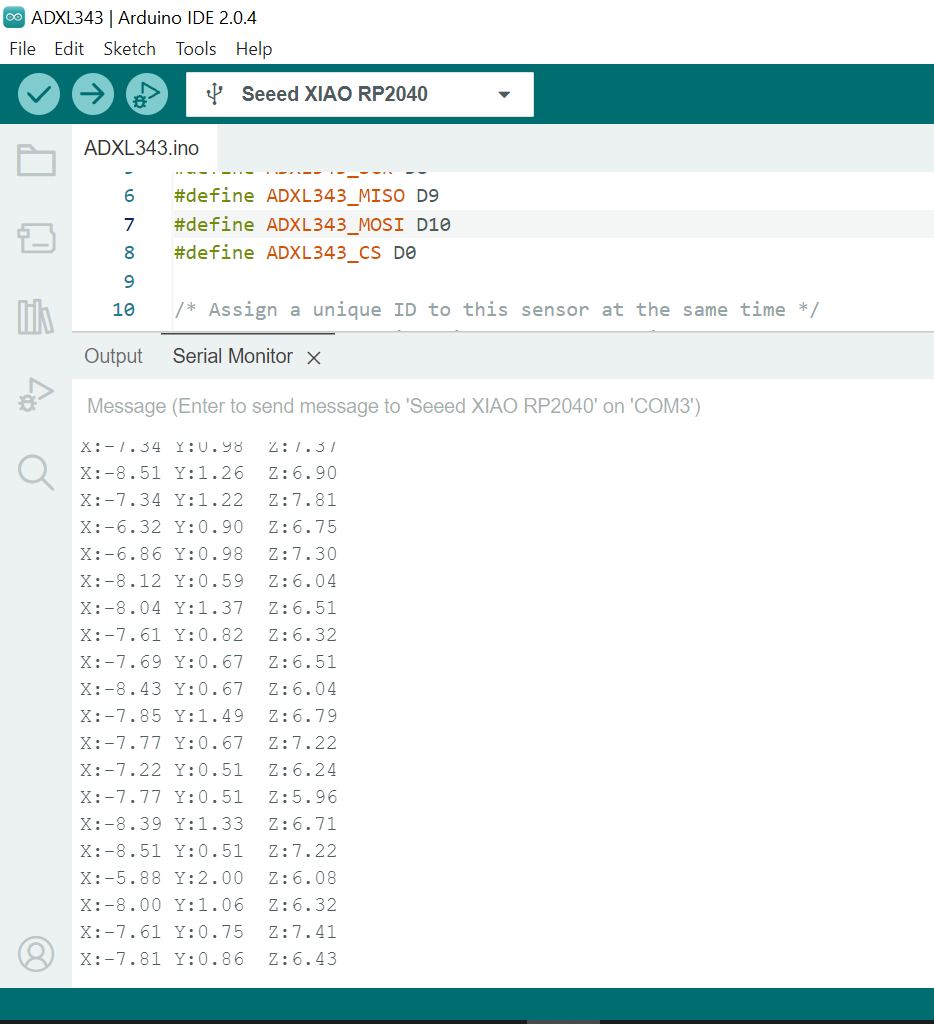
Below on the left are the values of the axes of the first test. Each axis shows some change in this screenshot. However, the numbers are quite messy. The X-axis seems to have the most variation, at least in this screenshot.
The picture below right shows the values of the axes of the second test. Here the variations are clearly smaller, which is not surprising as the wrists do not move as much when knitting.
I don't think I need this sensor for the final project, although it is true that this sensor could be used to measure movement, but I don't find it useful for my final project, at least not at the moment.
|
|
However, in this week's assignment, the input device was not allowed to be connected to the board with jump wires, it had to be directly soldered or connected with connectors, so I had to do some more. I didn't want to make a board for the accelerometer, so I decided to test the temperature and humidity sensor.
Temperature and humidity sensor AM2302/DHT22
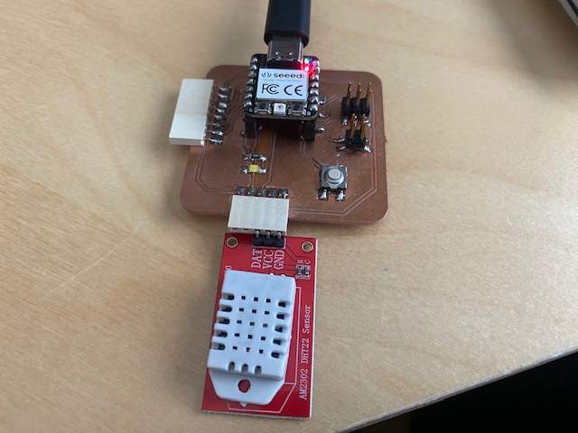
I tested the AM2302/DHT22 temperature and humidity sensor. I was able to connect the sensor directly to the male connector on the development board I made in week 8. The pins to connect were VCC, Ground and Data. The Data pin was connected to pin D4. This DHT22 has a pullup already inside. The setup is in the picture below.
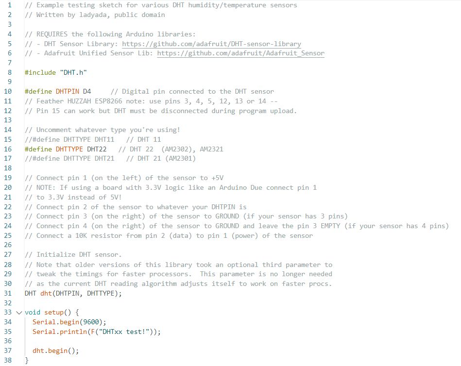
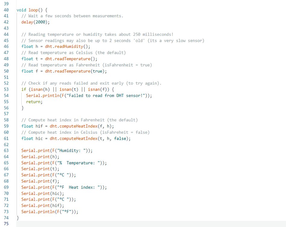
I used code from the Adafruit tutorial. I downloaded the "DHT library by Adafruit" library in Arduino IDE for the code. I defined the D4 pin in the code as connected to the DHT sensor. The full code is shown in the pictures below and can be downloaded at the bottom of the page. In the code a lot of parts have been commented out, because in the same code there were possibilities to use it also for the DHT11 sensor.
|
|
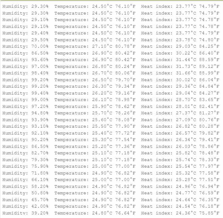
The pictures below show two different tests with the sensor.
In the left picture you can see the increase in humidity values when I breathed lightly on the sensor.
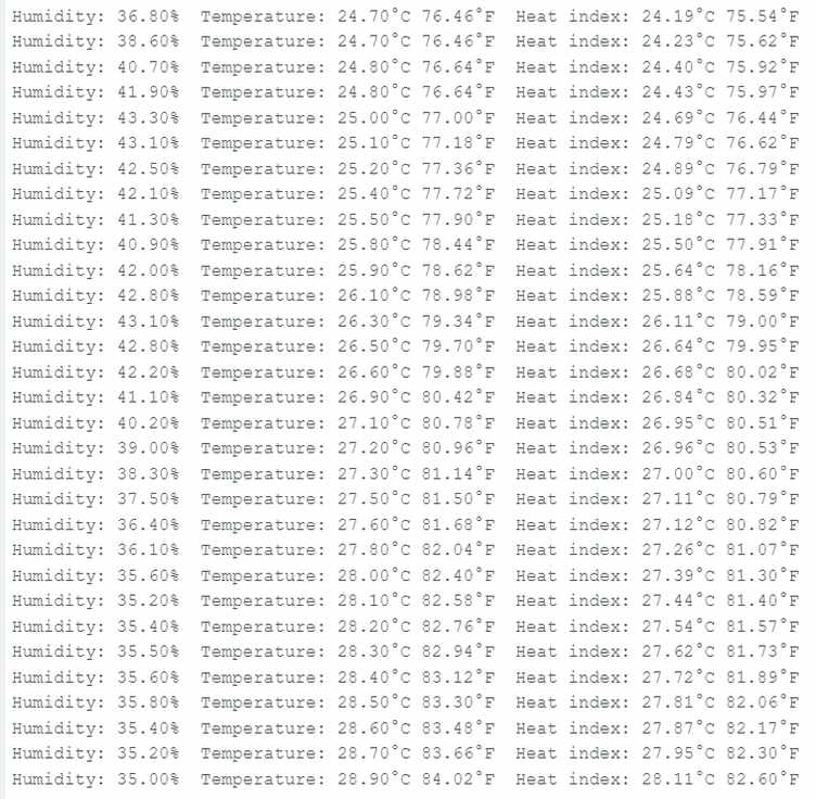
In the picture on the right, I placed the sensor against my coffee cup and the temperature values started to rise.
|
|
So the sensor seemed to work, and I would like to use it later to make my own thermometer and hygrometer.