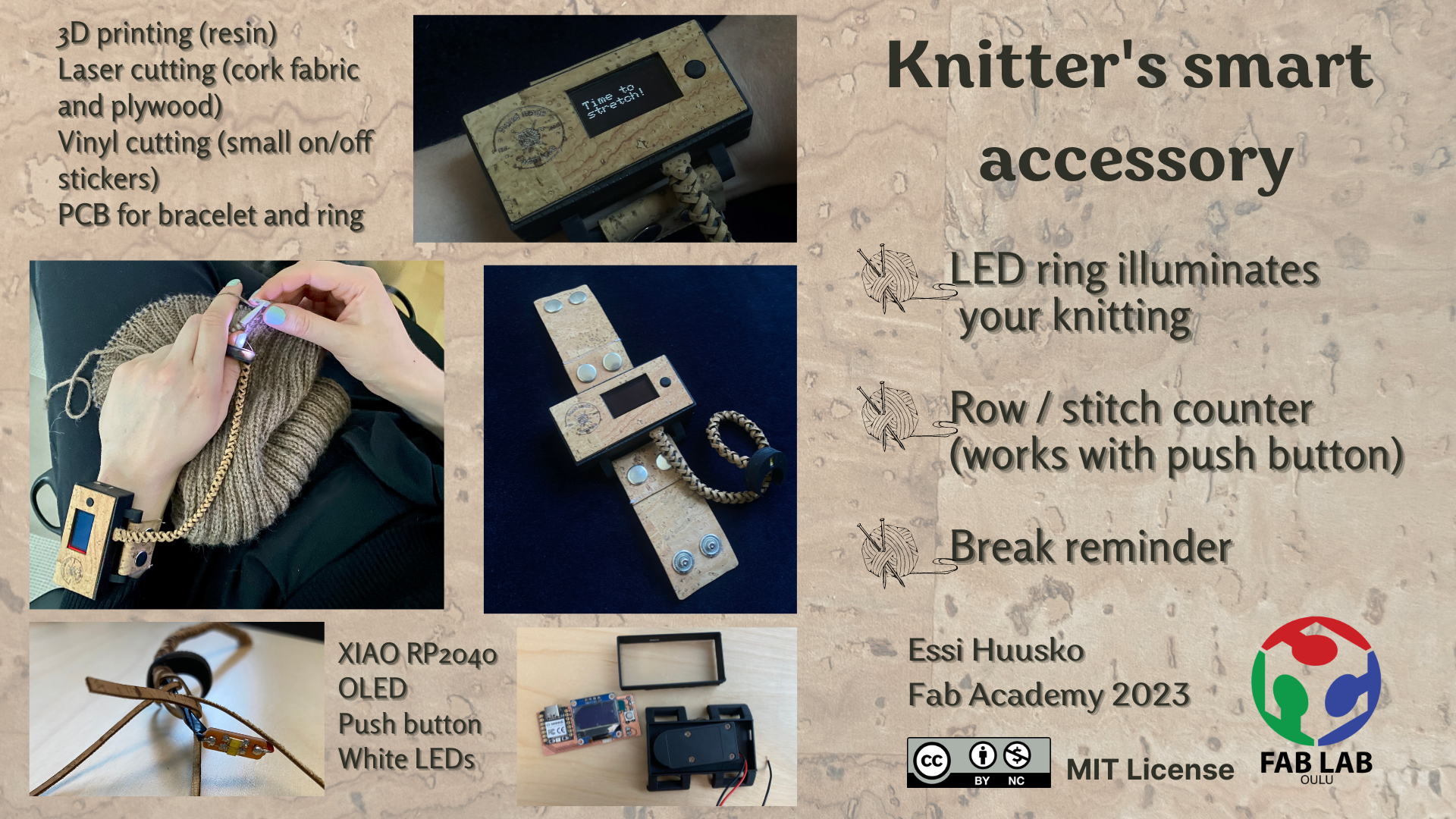
Final Project: Knitter's smart accessory
Presentation video:
Presentation slide:
The idea and sketches
While knitting in the dark Finnish winter, I was hoping for better spot lighting for my knitting. I wondered if it would be possible to make a LED ring to illuminate my knitting. I have seen people use headlamps or, more recently, a light around their neck when they knit. A small spotlight also worked well when knitting in the car, on the bus or even watching a movie. This was my biggest dream, but I had to plan a little more for the final project.
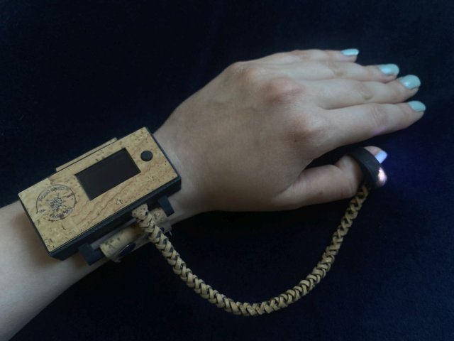
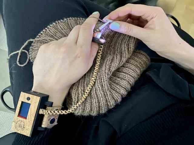
I realized that there was no way I could make a fancy ring with my own skills that had a tiny rechargeable battery to power it. This gave me the idea of a bracelet with a power supply that would power both the LEDs and other components of the accesssory. The final project also required some programming, so I thought a row counter would be a handy tool for knitting, so that, at least I wouldn't have to mark rows in my phone notes or write them down in the corner of the knitting instructions. It would be nice to have the row counter just one button press away without the presence of my phone.
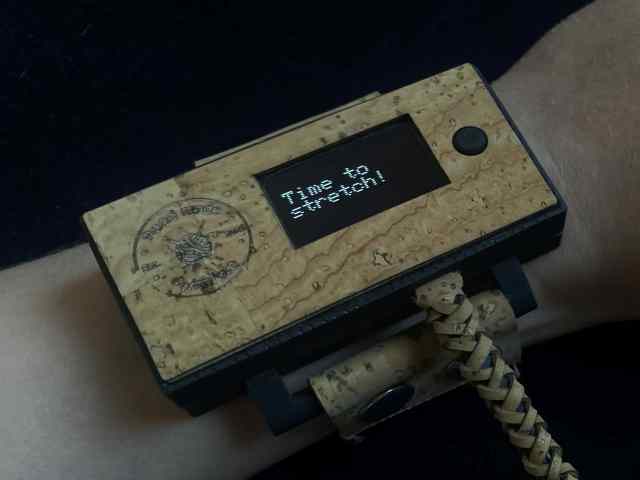
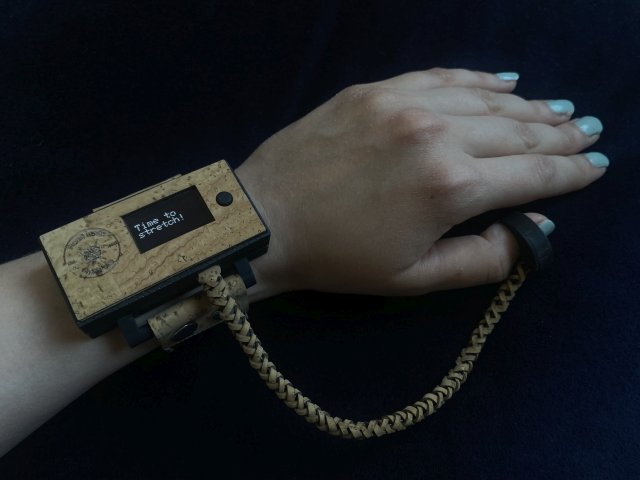
This smart accessory will also have the break reminder, which reminds you every 30 minutes with the text "take a break, stretch, etc." displayed on the OLED screen. At the same time, the LED lights turn off for the break.
The knitter's smart accessory is something I haven't seen yet and that's why it inspires me!
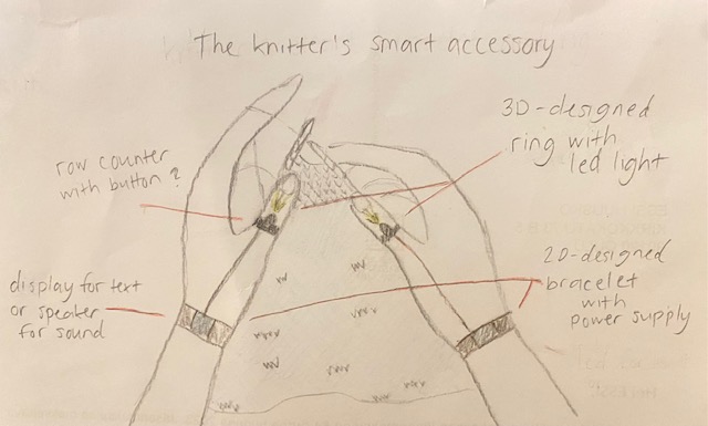
Below is the sketch of the final project made in Inkscape during the week 2. Check out the documentation here.

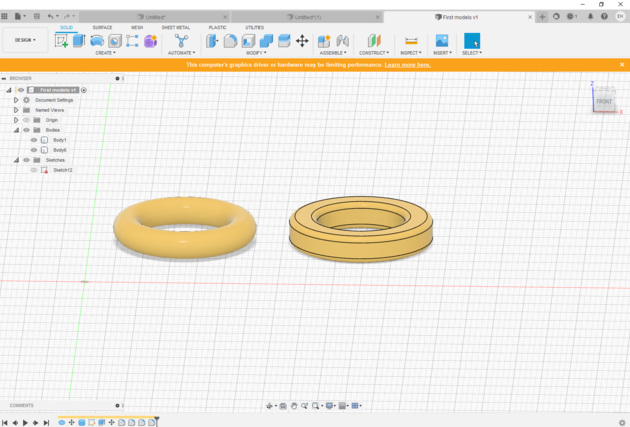
3D Modelling and printing
Below are first 3D modelling tests of the ring from week 2. Check out the documentation here.
|
|
|
|
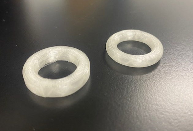
I tested the rings on my thumbs while knitting, but I couldn't get a picture of the testing for this documentary as I was alone. After these tests, I wonder if the rings even need to be on both thumbs, because possibly the light from one ring can be enough and it's almost easier to have the ring on the left thumb only. The left hand is much more passive while knitting, so the ring is not distracting at all. In addition, the left thumb stays in place, so the light is always directed to the right spot.
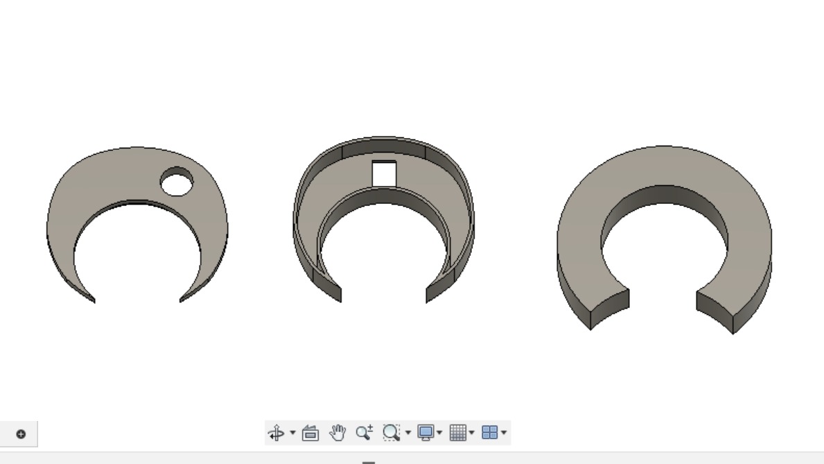
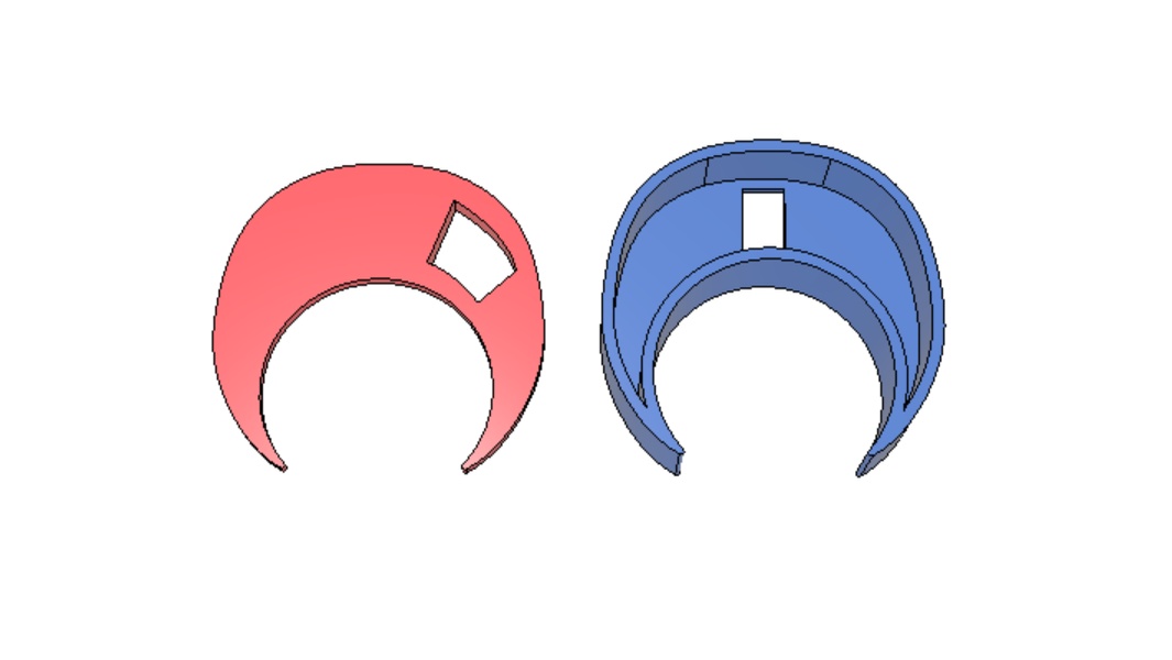
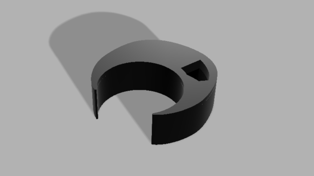
The shape of the ring could also be an incomplete circle, which would leave the base of the thumb free and make knitting more comfortable. I had planned the first split ring to be up to 10 mm width, but I think the narrower the better. So these were good first experiments, because I already got some ideas for further development!
Next, I did a test of a shape of a crescent moon and it worked well, so I started working on the design further.
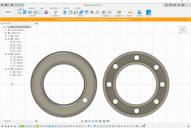
I designed the parts for the final project using the lessons I had learned from using Fusion during the Fab Academy. I've spent some time modelling the ring and the bracelet case doing several experiments to find the right size. The challenge has been to make small enough, but also big enough to fit all the stuff inside the ring and bracelet case.
Below is the final design of the ring, which I have increased in size so that the circuit board I made fits inside, plus the wires fit through the hole.
|
|
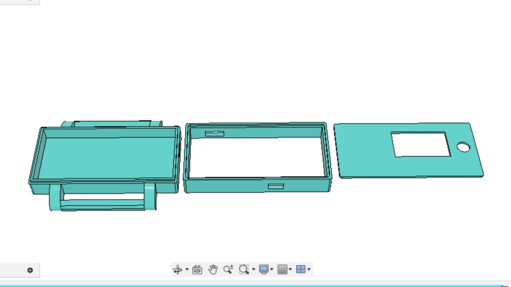
I wanted to make the bracelet case out of two detachable parts to make it easy to change the batteries. I did some experiments on the case, first to find the right places for all the holes, i.e. holes for the ring wires, for the c-port of the microcontroller and for the battery switch.
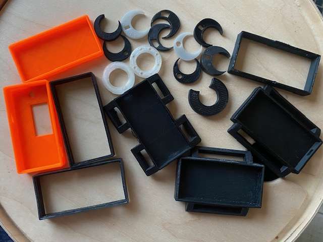
Once the holes were in the right places, I thought about the attachments for the bracelet straps, what width the attachments would be, whether there would be one or two... Below in this section is a picture of almost all the test pieces I made both to try out the models and to try out a successful print.
At the same time, I used Fusion to design a cover for the case, which I then later edited in Inkscape. I wanted to laser cut the cover out of plywood/cork fabric to make the look of the case more special in some way. The first model of the case was completely 3D printed including the cover, but somehow it felt too plastic and meh.
Below is the final design for the bracelet case:
|
|
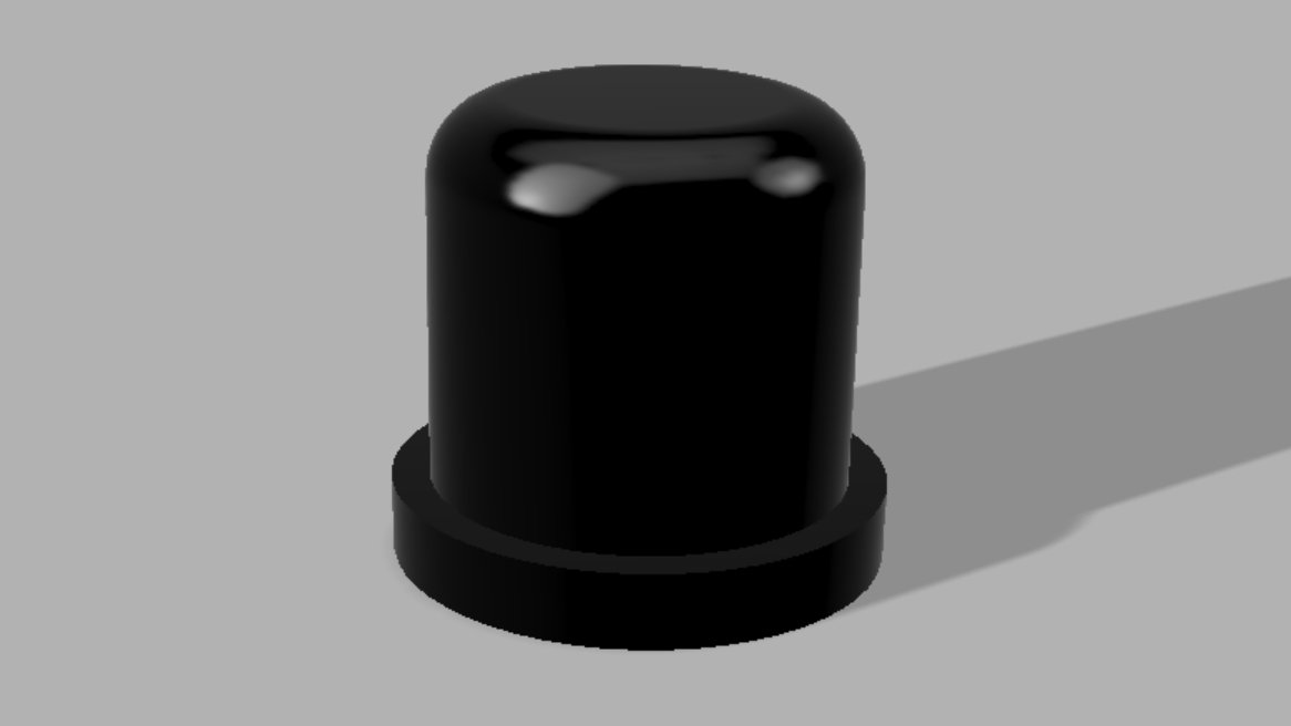
The last thing I 3D modelled was "a higher" push button for the push button on the PCB to work with the case. From this I also tested a few different heights before finding the final one.
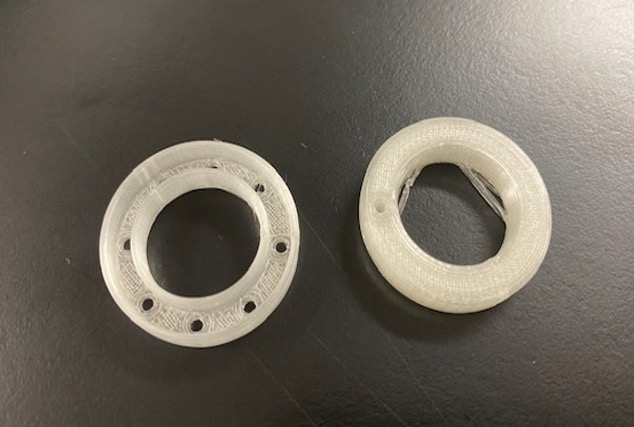
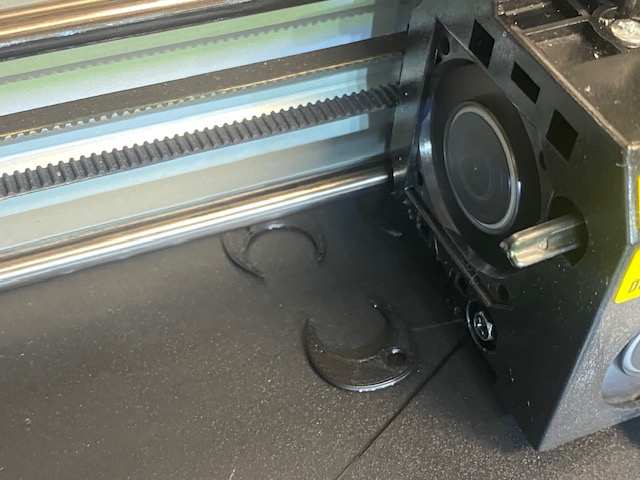
I did test prints with PLA filament because the prints took shorter time when I didn't make the infill high density. It was also more pleasant to use such bio-based materials for tests. I used a Sindoh Wox dp201 printer for the tests and a 3DWOX slicer. 3D printing was done as I had learned in week 5. In the picture below left, the printing of the test ring in progress. On the right is a collection of almost all the test pieces and failed prints that I tested.
|
|
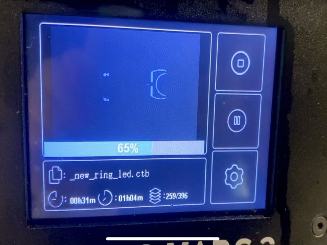
I 3D printed the final parts of my final project from resin. This gave me a better finish, as the layers blended together in the print. I used ELEGOO Mars 2 MSLA Resin 3D Printer and chitubox slicer in the BusinessAsema Fab Lab. Sometimes the prints went wrong and often only one of the two pieces would print, but by adjusting the settings; extending the exposure time and increasing the density of the support, I eventually got working parts.
The picture below left shows one layer of the ring from the MSLA print and on the right are the parts of the bracelet case hardening in the UV oven.
|
|
2D Modelling, laser cutting and vinyl cutting
I used Inkscape to make the final design for the bracelet case cover, design for the straps and 4 strand ribbon for braiding and also a simple lettering design for the on/off marking of the battery holder switch. The use of Inkscape was practiced in weeks 2 and 3, for example.
The base of the bracelet case cover was first designed in Fusion, as you can see in the 3D Modelling and printing section. I made the stroke width changes for the laser cutter using Inkscape and added an engraving design to the cover. For the engraving design, I found the idea and the free license base from the Freepik website. I made some modifications in Inkscape to make the small engraving at least a little clearer.
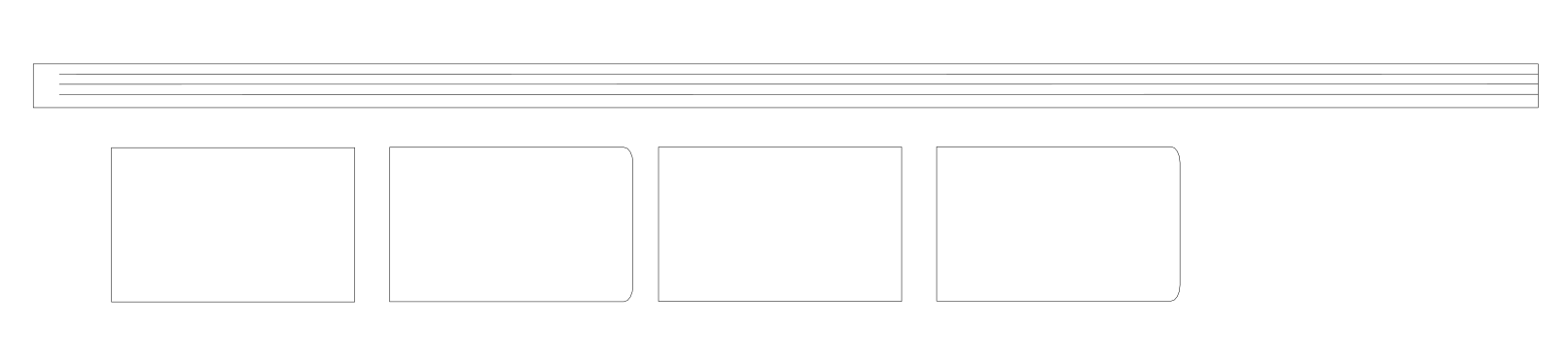
Below left is a picture of the design for the bracelet case cover in Inkscape and on the right is the design for the letters to be vinyl cut.
|
|
In the picture below the design for the straps and the 4 strand ribbon. The designs had to be made according to the material, of which more below.
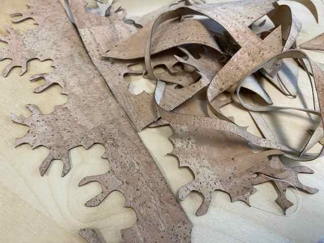
For the straps of the bracelet I considered different leathers and also cork fabrics, but in the end I was most inspired by this natural coloured cork fabric. I had been saving pieces of this cork fabric from a customer's leftovers that were going to the trash, because I thought I could make something out of them. And so I could... In the picture below left, you can see the leftover pieces I had, which I then used to figure out how to cut the straps and also the 4 strand ribbon for braiding. And on the right is a picture of the laser cutting of the pieces I designed. I designed the straps of the bracelet from two pieces, so that I could cut them from leftover pieces. More about using the laser cutter and vinyl cutter in week 3.
|
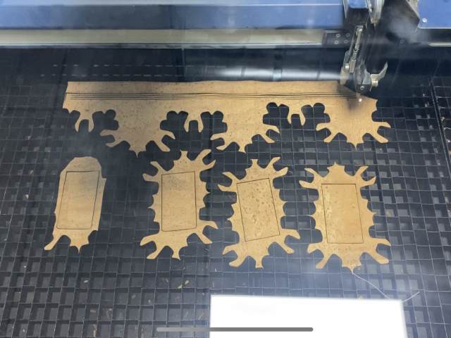
|
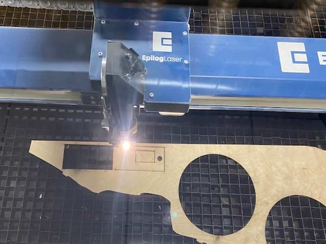
For the cover of the bracelet case, I first cut a piece of thin plywood, less than 1 mm thick, to support the cover cut from the cork fabric. Picture below left. On the piece I laser cut from the cork fabric, I also engraved the engraving I had designed. Picture below right. It was difficult to make the fine details of the engraving visible on the cork fabric, but I'm happy with the result. I glued the cork to the plywood.
|
|
I used a vinyl cutter to make small stickers on the case to know if the battery was switched on or not. Pictures below.
|
|
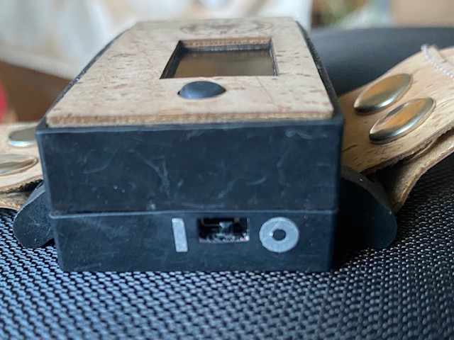
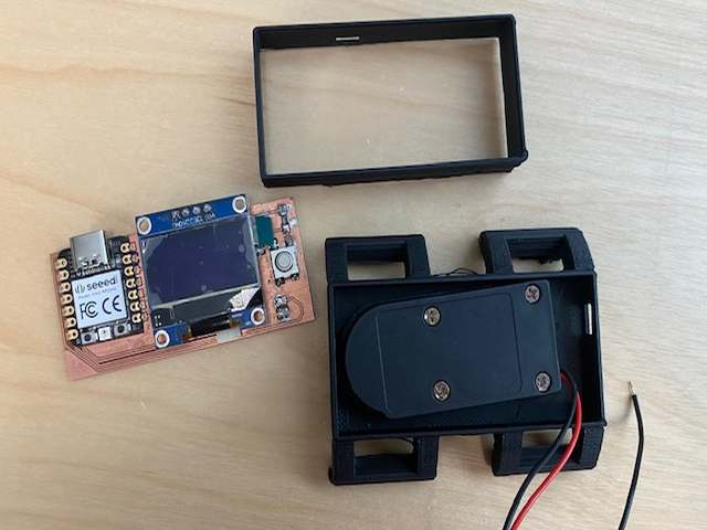
Electronics design and production
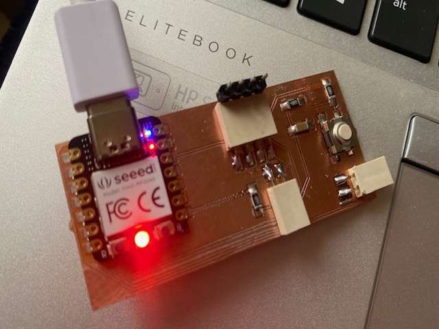
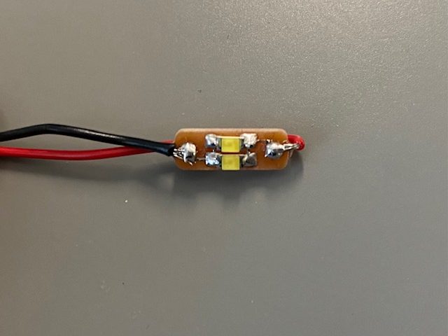
For this final project I made two circuit boards, one for the ring and one for the bracelet. The circuit board on the ring only have LEDs and the power will run from the circuit board on the bracelet to the ring. The circuit board for the bracelet have OLED, push button and RP2040 and the necessary resistors, capacitors and connectors. The accessory can be powered either by batteries connected to the bracelet (2 CR2032 batteries in series) or alternatively via a 5V USB cable. These of course must be used separately.
I designed and produced the circuit boards using the knowledge I had learned in Electronics design and production weeks. During the Electronics production week, I purposely soldered a white LED to my circuit board so I could see how bright it was and test the illumination. This testing of the LED on the circuit board allowed me to directly choose the same white LEDs for my final project, which I decided to put two in parallel on the circuit board of the ring. Also, the OLED testing in the Output week helped me understand how to design the OLED placement on the circuit board. Obviously there were still some questions to be answered in this project, for example, creating a debouncing button on a circuit board was new to me and I got help from the instructors.
Below are the KiCad Schematics for both circuit boards.
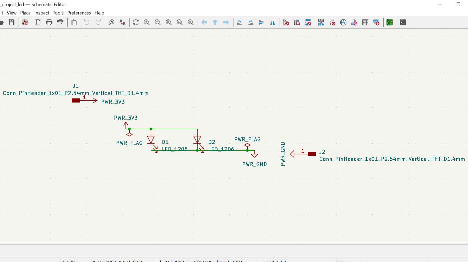
|
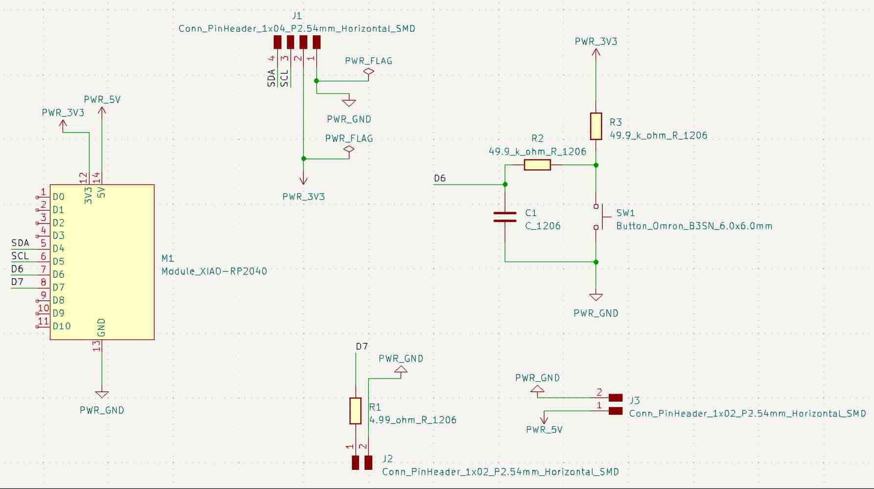
|
And KiCad PCB Editor designs for both circuit boards:
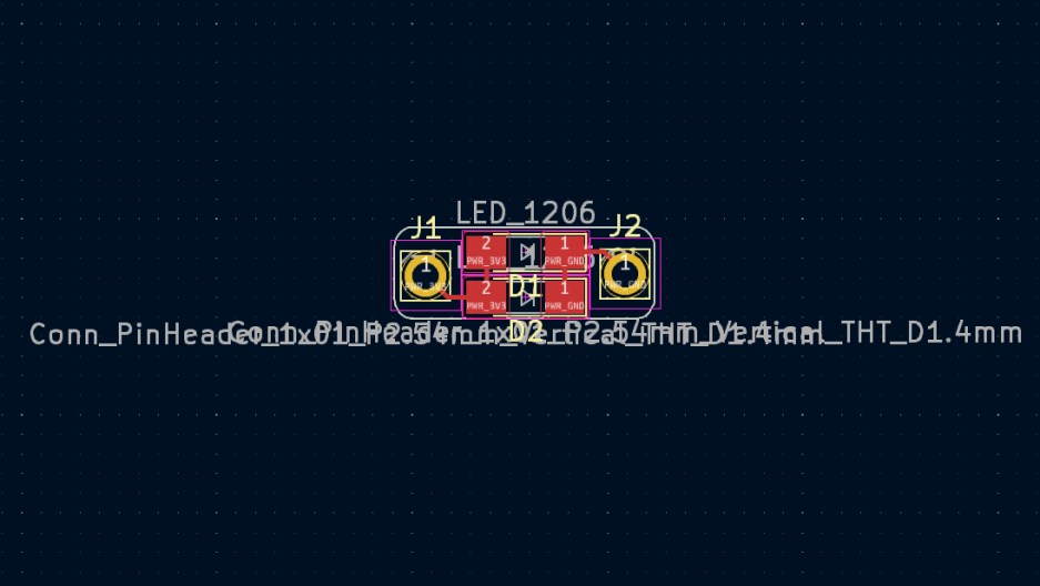
|
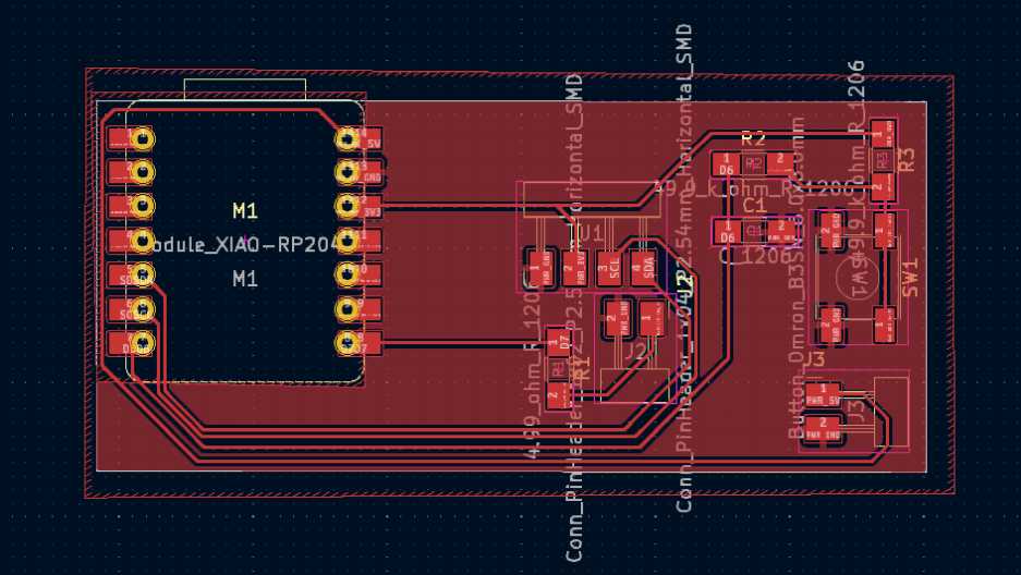
|
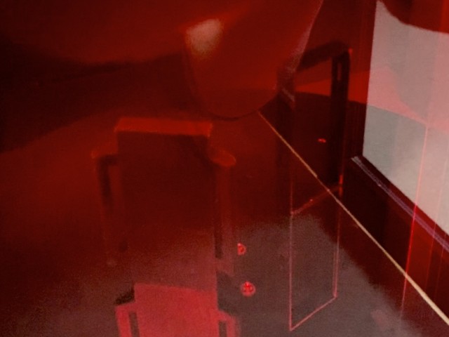
I made the boards with the LPKF milling machine and the milling went well. Picture below left. The only thing I hadn't thought of was set drill holes for the Gerber file on the circuit board of the ring. The holes would have been for the wires to come through the hole and then be soldered to the pad around the hole. But instead of making a new circuit board, I tested that the wires could bend over the edge of the circuit board. Below, on the right, the milled boards are waiting to be soldered.
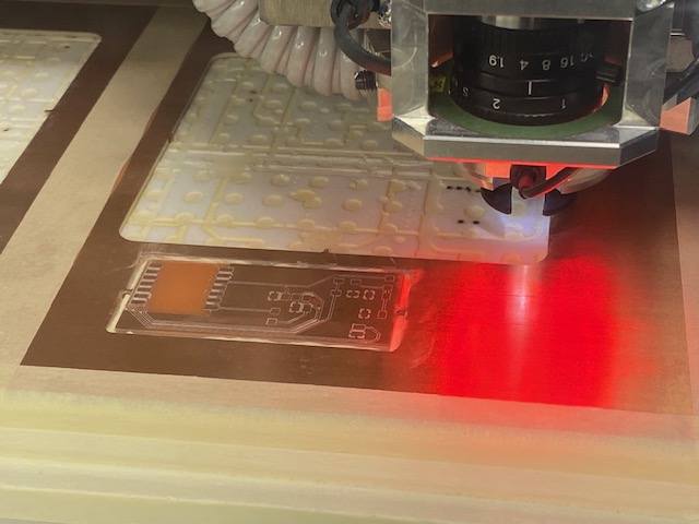
|
|
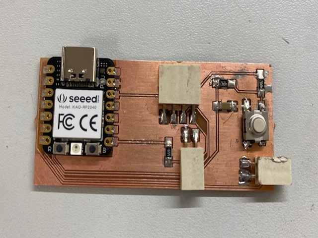
To make the circuit board for the bracelet, I used low temperature solder paste and a reflow oven to solder the microcontroller, button, resistors and capacitor. The connectors I soldered by hand. I did the soldering one evening after a much too long day and felt that the soldering could have gone better.
When testing the circuit board there were short circuits, the paste had gotten around under the button and the button's resistors. They then had to be removed and the solder removed with a desoldering braid, but eventually all the short circuits were gone. In the picture below left you can see that the board and components took a bit of a hit when the repairs were made. In the picture below right, testing the board.
|
|
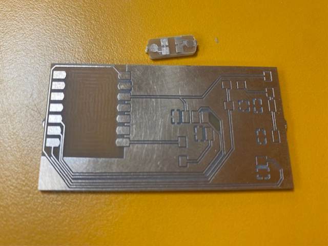
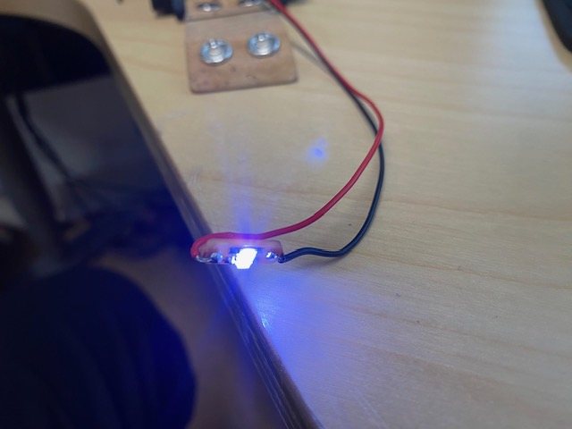
I soldered the circuit board of the ring all by hand and it worked on the first try, yippee! Pictures below.
|
|
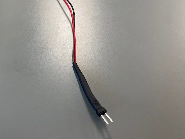
I soldered male connectors to the ends of the wires and covered both solder joints first with own heat shrink tubes and then the whole thing with one more. Picture below.
Programming
The idea behind the Knitter's smart accessory programming:
- The LEDs turn on when the power is switched on.
- The counter works at the press of a button. For example, when the first row with stitch decreases has been knitted, press the button and the display will show the counter reading 1 for a moment and the number of rows is stored in the memory. Knit the next row and press the button and the display will show the total number of rows: 2. And so on. The number of rows does not need to be stored in memory when the power is switched off, but only for the moment you knit.
- The break reminder reminds you every 30 minutes with the text "take a break, stretch, etc." displayed on the OLED screen. At the same time, the LED lights turn off for the break.
- When you have had a break, the break is cancelled by pressing a button and the LEDs turn on again.
I first tried building the programming with separate codes, so that the necessary codes would be clear at the same time. My colleague gave me some tips on how to write the codes, because, as I say many times in the Fab Academy documentation, my coding skills are quite weak and I haven't had time to learn much during these weeks.
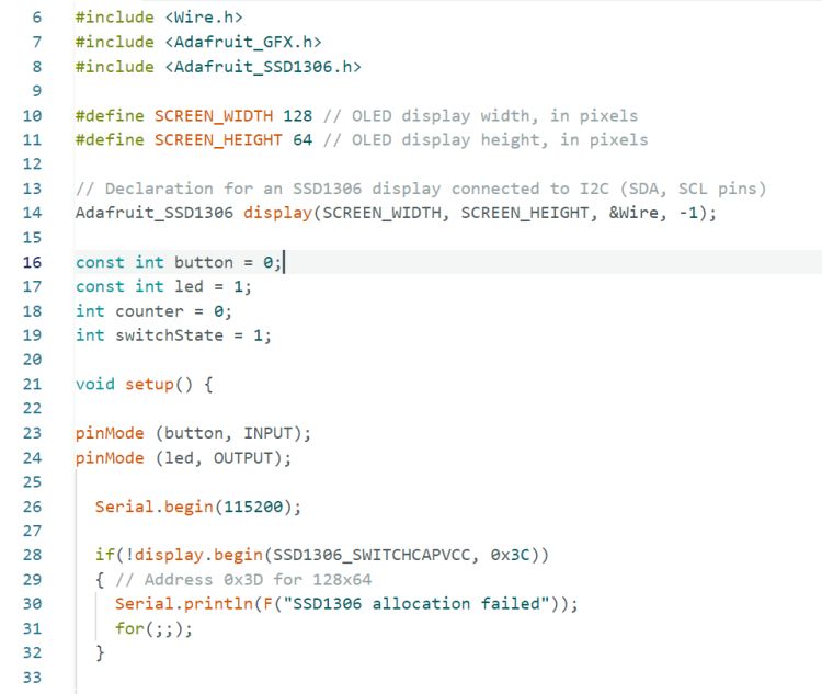
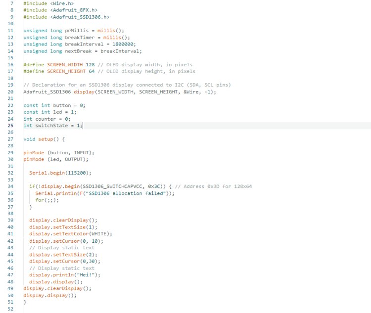
Below is the first version of the row counter code. I used the lessons I learned in the Output week to program the OLED. I was surprised how simple this kind of counter code is, because I was not familiar with counter code before.
|
|
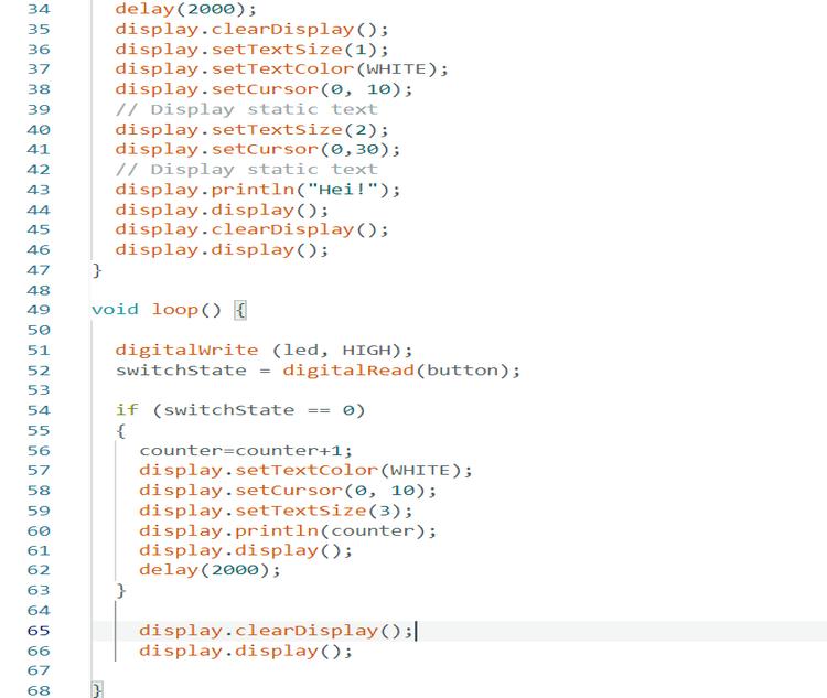
Below is also the first separate code for the break reminder, which also used a counter.
|
|
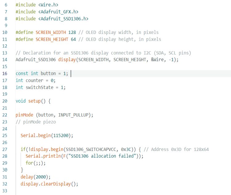
Well, after trying these two separate codes, I wondered if there was a problem with both of them using counters. I also wondered how delay() affects in the programming and remembered the words of our instructor Gleb about the use of millis(), which could be useful for different programming. I wanted to explore the possibilities of millis().
I started to figure out how to first use millis() instead of delay(), so that in the part of the code where the row number is displayed, it would show up for a moment and then the display would clear. I managed to find an option using the while loop, tested it and it worked.
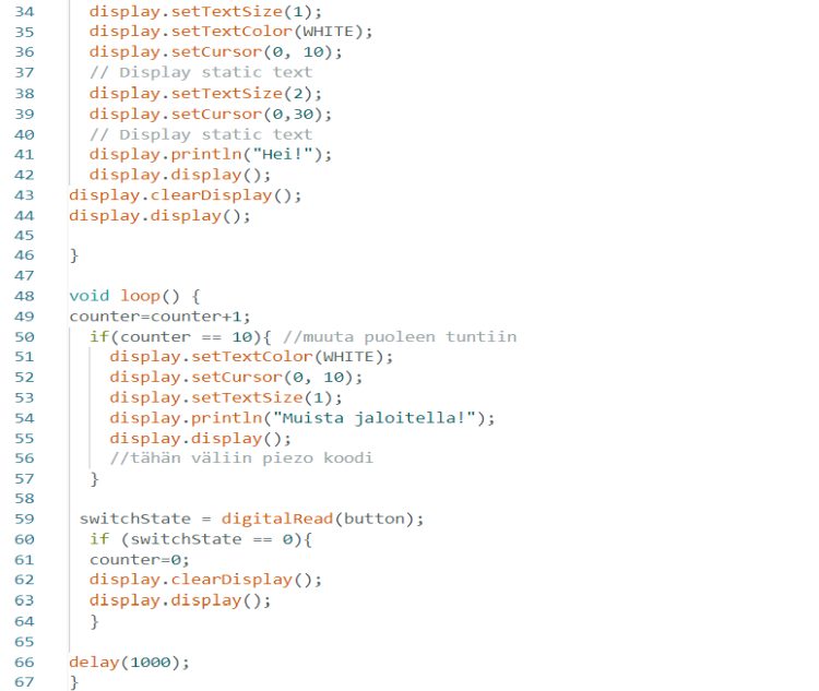
I found tips on how to build the code for the break reminder in Youtube videos, but I also got help from my colleague and now with unsigned long lines it was possible to declare the variables:
- prMillis: holds the current time in milliseconds
- breakTimer: keeps track of the time since the last break
- breakInterval: the duration (in milliseconds) between breaks
- nextBreak: stores the time when the next break should occur
|
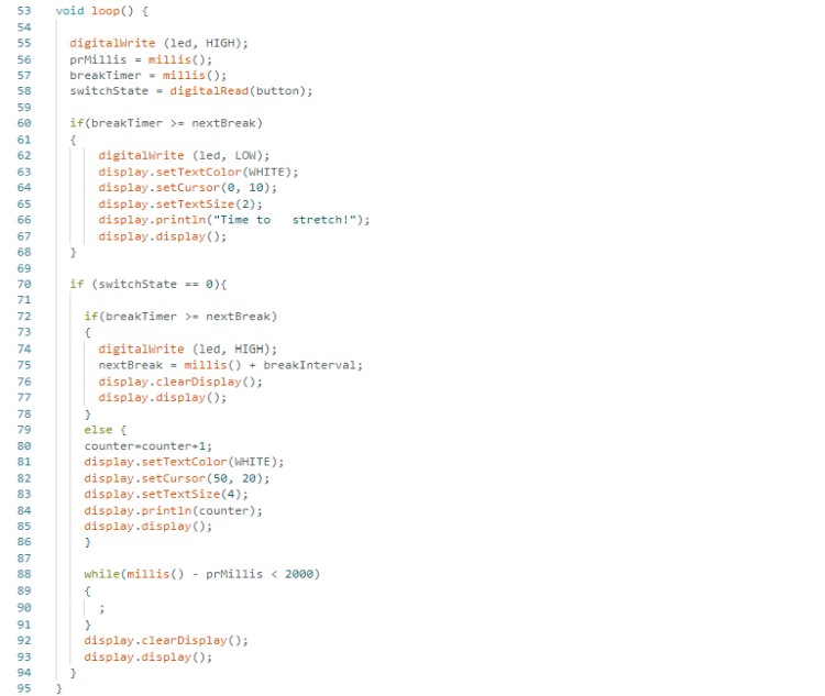
|
Testing, assemble and details
Along the way, of course, parts of the project also had to be tested, even in silly-looking ways, in order to see in which direction the project is going. The picture below on the left shows the first test version of the bracelet case with two separate attachments for the straps. I didn't like the design. Below on the right, unfinished parts are excitedly connected here and there, so I can see how the project would look like.
|
|
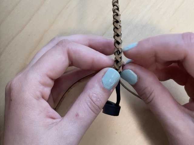
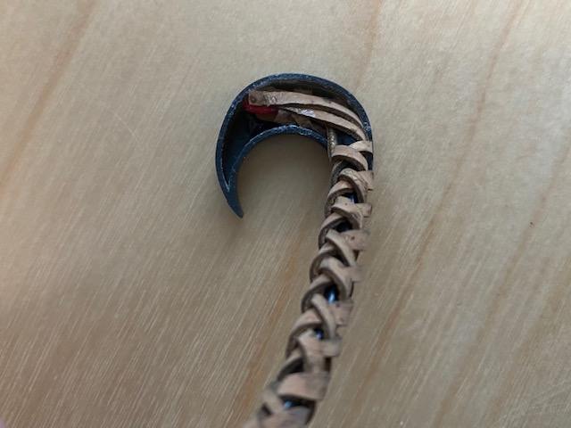
To hide the wires going from the bracelet to the ring, I figured out to braid a 4 strand cord around them. I was also able to use the same cork fabric for this, so it worked well. Picture below left. I glued one end of the cord to the base of the male connector and the strands of the other end inside the ring. Picture below right. It might not look like the prettiest solution there, but I managed to hide it well when I put the ring's back piece on.
|
|
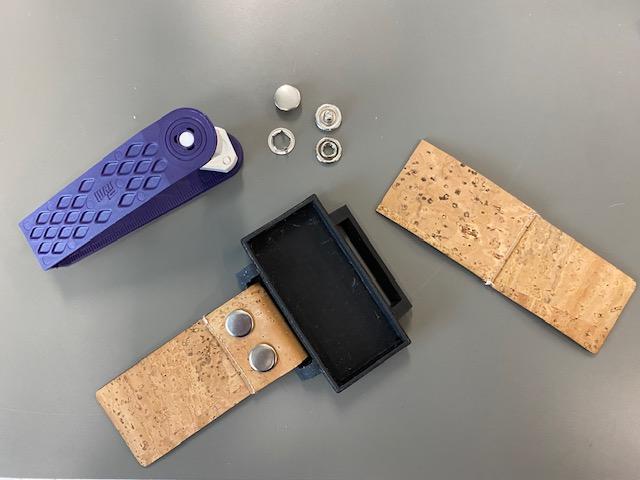
I fastened the straps with snap buttons. In the picture below, you can also see the seams, which I purposely made visible so that I could use the leftover pieces.
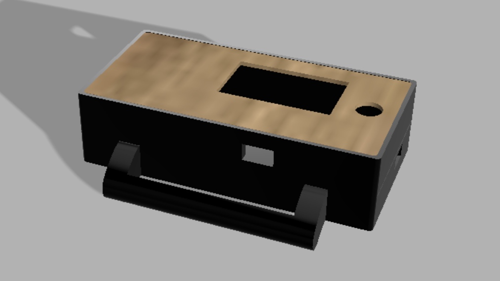
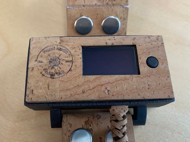
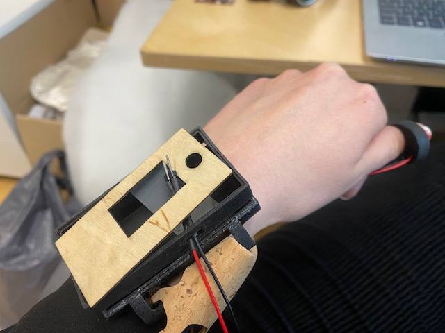
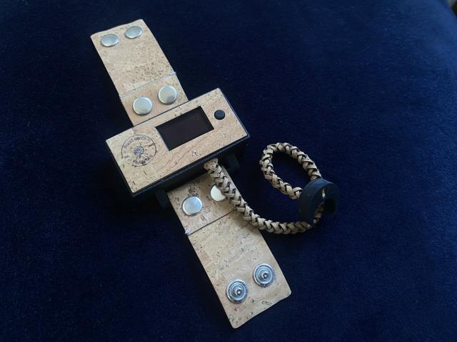
Finished product and development ideas
I think the project turned out to be quite good-looking, even though I've said this is just the first prototype (the next versions aren't coming right away though... I have to recover from this spring first. :D).
The first development ideas I have in mind are to reduce the size of the package, or at least the bracelet, and to come up with a longer-lasting or rechargeable battery. So there is a lot of electronics involved and there is so much for me to learn in those subjects.
Pictures of the finished product below:
|
|
|
|
Bill of materials
Materials:
| Material | Price | Link |
|---|---|---|
| PLA filament and resin from BusinessAsema Fab Lab | 10 € | 3D-Cadsolutions |
| Cork fabric leftovers from BusinessAsema Fab Lab | 8.50 € (I used the leftovers, so practically 0 €) | Ullaka |
| Snap buttons from Kärkkäinen | 5.60 € | Kärkkäinen |
| A small amount of sewing thread from BusinessAsema Fab Lab | around 0.30 € | Ullaka |
| Summary | around 27.10 € |
Components:
| Component | Price | Link |
|---|---|---|
| XIAO RP2040 from Fab Lab Oulu | 5 € | DigiKey |
| 2 x LED white 1206 from Fab Lab Oulu | 0.20 € each | DigiKey |
| OLED display from Fab Lab Oulu | 3.66 € | Amazon |
| Push Button from Fab Lab Oulu | 0.80 € | DigiKey |
| Capacitor 10 nf from Fab Lab Oulu | 0.05 € | DigiKey |
| 3 resistors (R1: 4.99 ohm, R2 and R3: 49.9 kilo ohm) from Fab Lab Oulu | 0.01 € each | DigiKey |
| PCB material, some wires, connectors, solder from Fab Lab Oulu | around 3 € | DigiKey |
| Battery case 2 x CR2032 from SP-Elektroniikka | 3 € | SP-Elektroniikka |
| 2 x battery CR2032 | 1.20 € each | SP-Elektroniikka |
| Summary | around 18.34 € |
Total cost of materials and components is around 45,44 €.
Licenses
The software of this final project is licensed under MIT license.
Other parts of this final project is licensed under Creative Commons Attribution-NonCommercial 4.0 International License.
Files
Download bracelet case design F3D file
Download pushbutton design F3D file
Download case cover design SVG file
Download straps and 4 strand ribbon design SVG file
Download on/off stickers SVG file
Download ring pcb KiCad Schematic file
Download ring pcb KiCad PCB file
Download bracelet pcb KiCad Schematic file