2. Computer-aided design
Individual assignment for this week:
- Model (raster, vector, 2D, 3D, render, animate, simulate, ...) a possible final project, compress your images and videos, and post it on your class page
I did 2D and 3D modelling training using Gimp, Inkscape and Fusion 360. I also spent quite a lot of time editing and compressing videos and images. While modelling, I took a lot of screenshots and also tested screen recording with Windows' own built-in tool. It went fine, but after making the recordings, I noticed that the menu openings and key combinations did not appear on the video. I downloaded the Carnac tool just for the sake of getting the key combinations to appear on the video. Well, afterwards I added text about the key combinations used and the actions in the videos..
When I was making the documentation for the website, I realized that I had perhaps saved too many screenshots and videos, and if I had put them all on the website, it would have been too full. So I decided to leave most of the screen recordings in the archive and took a few screenshots of the videos to supplement the verbal documentation. The softwares I downloaded and used to edit the images and videos were OpenShot, ImageMagick and HandBrake. In OpenShot I sped up and edited the videos, in HandBrake I compressed them. In the beginning I used Gimp to compress individual images, but I practiced using ImageMagick command-line to compress more images at once. I also used paint.net for basic picture editing, as I have it ready on my work laptop.
Raster graphic - Gimp
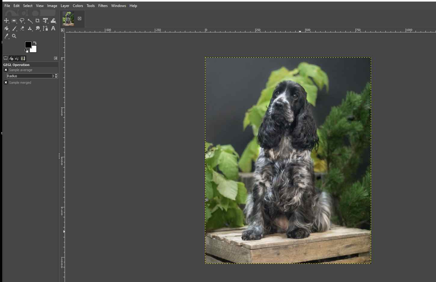
I couldn't figure out anything interesting about raster image editing for my final project, so I decided to test the image editing for laser cutter that I had in mind for a while. I wanted to give my sister image of her dog engraved on plywood, and here's a documentation of the image editing with Gimp.
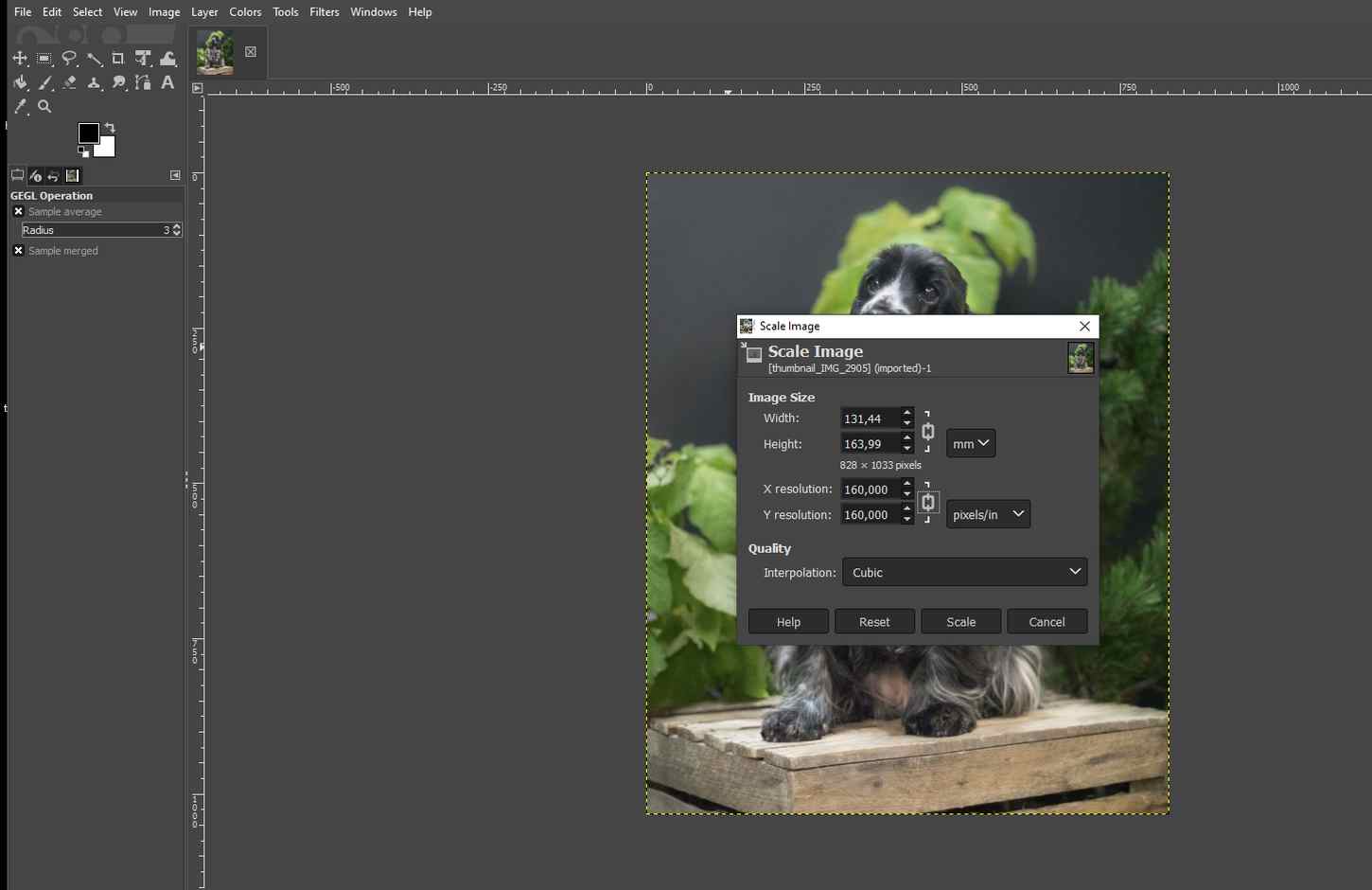
First, I opened the selected image in Gimp: File -> Open... Then I navigated to Image -> Scale Image and resized the size of the image close to the size of a postcard.
|
|
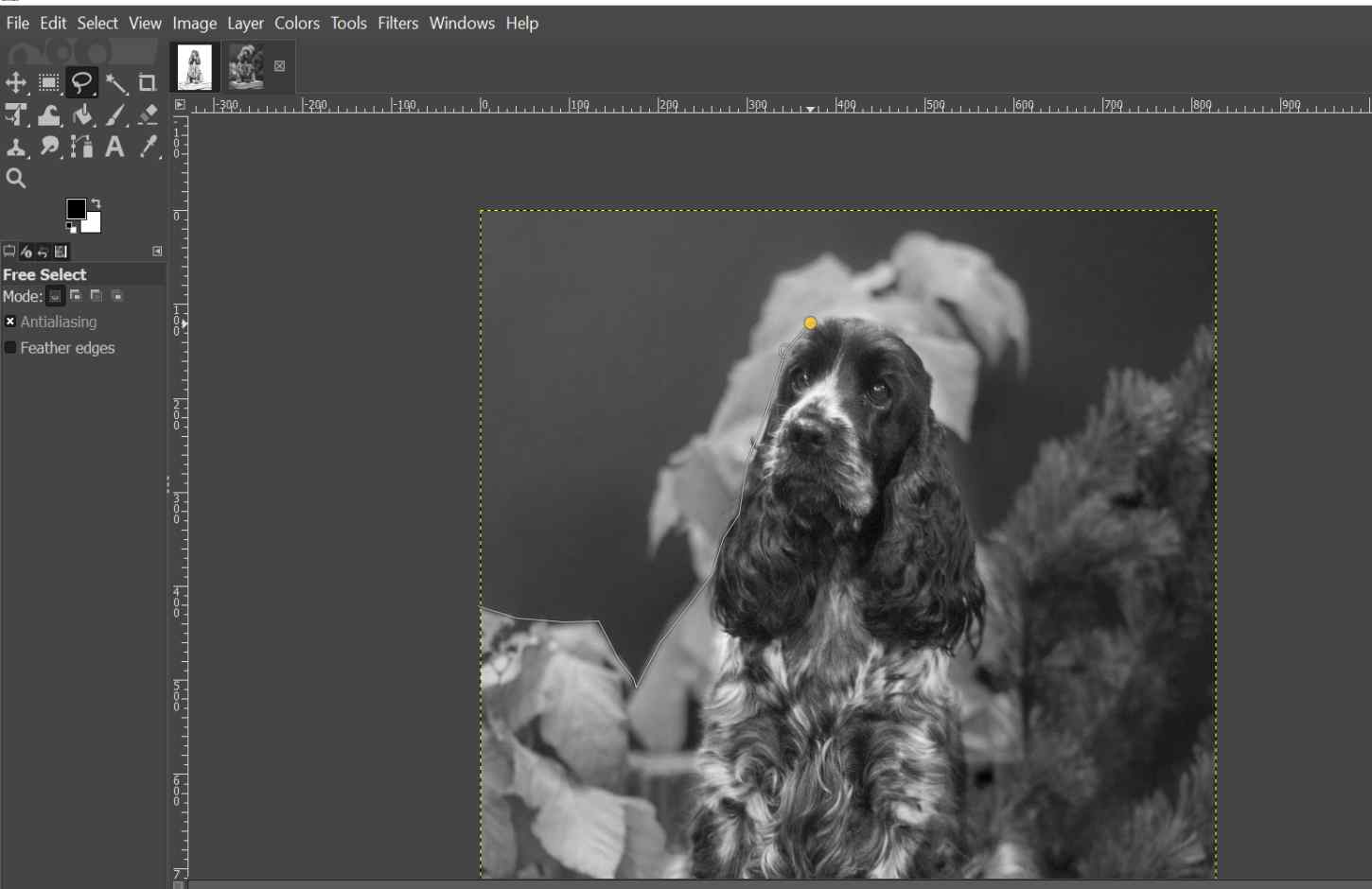
I changed the image to a grayscale: Image -> Mode -> Grayscale, making it easier to see the brightness of the image.
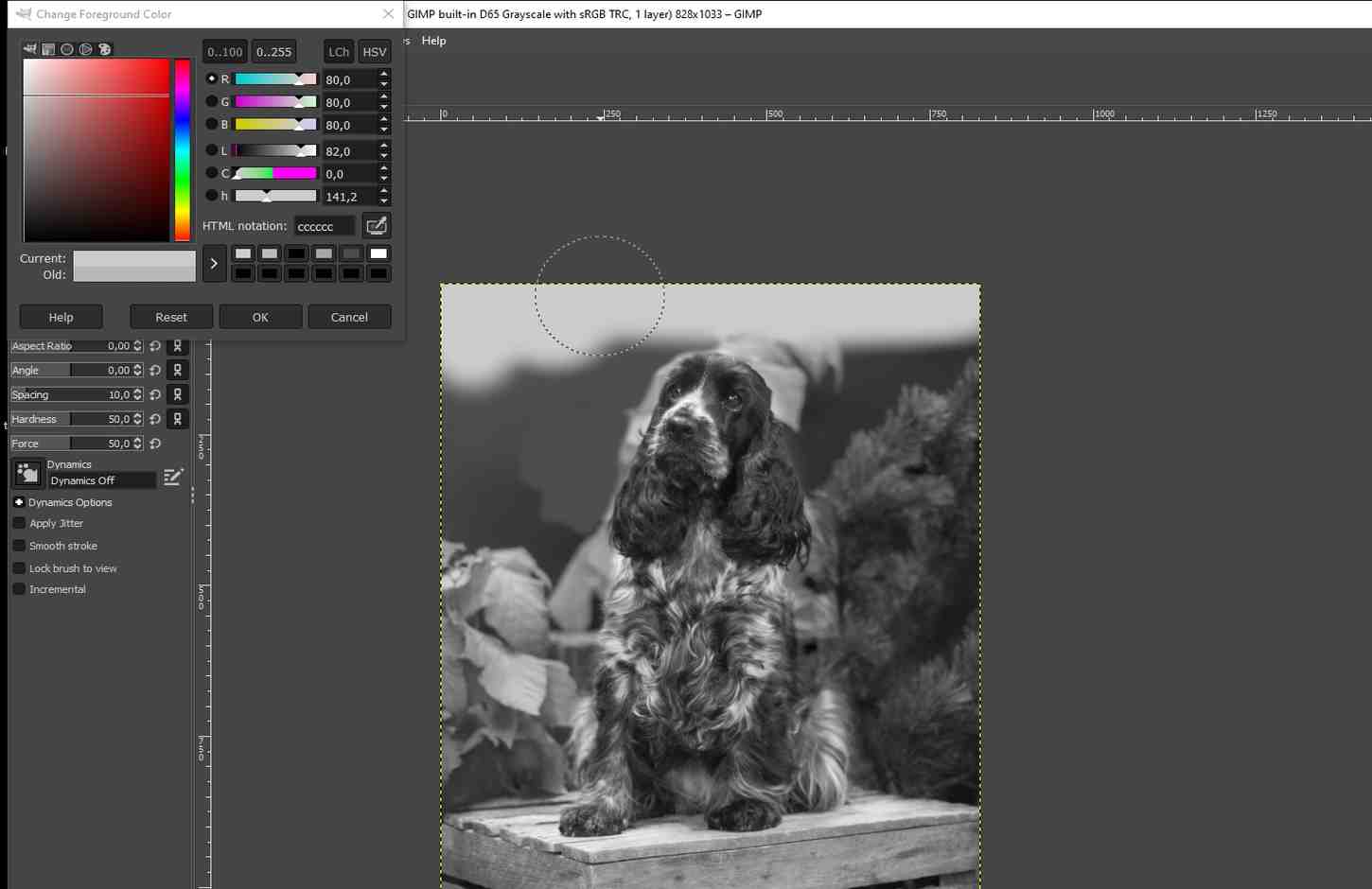
Then I started thinking about editing the dog's background. At first I was going to cut out the background using the Free Select Tool from Toolbox (image below left). However, I didn't want the background to be so clean and sharp and I decided to test the Paintbrush Tool to paint the background a very light grey (image below right). I left a bit of the plants visible at this point.
|
|
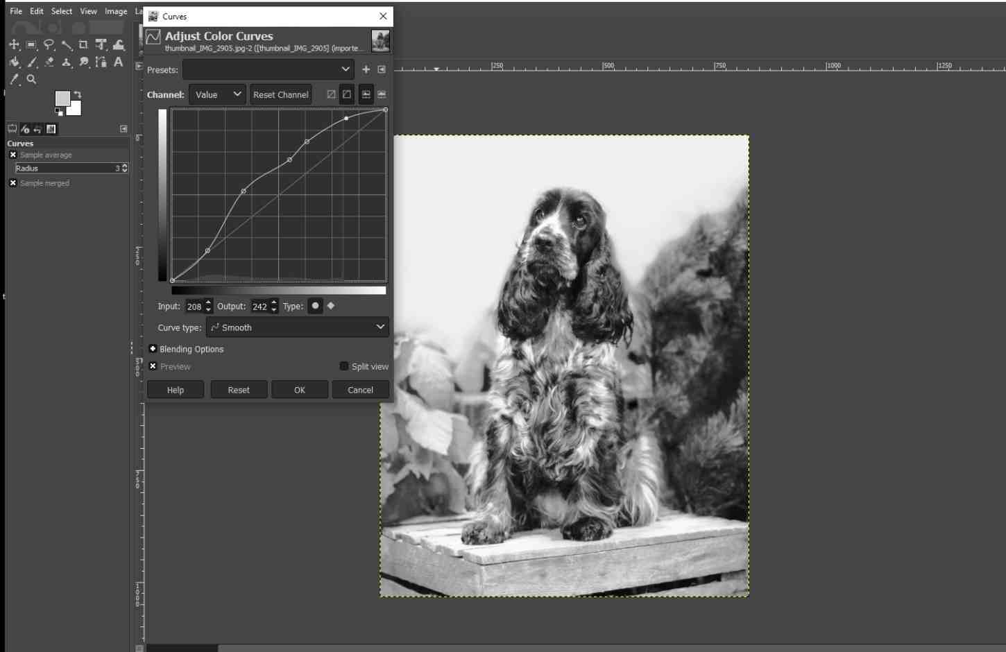
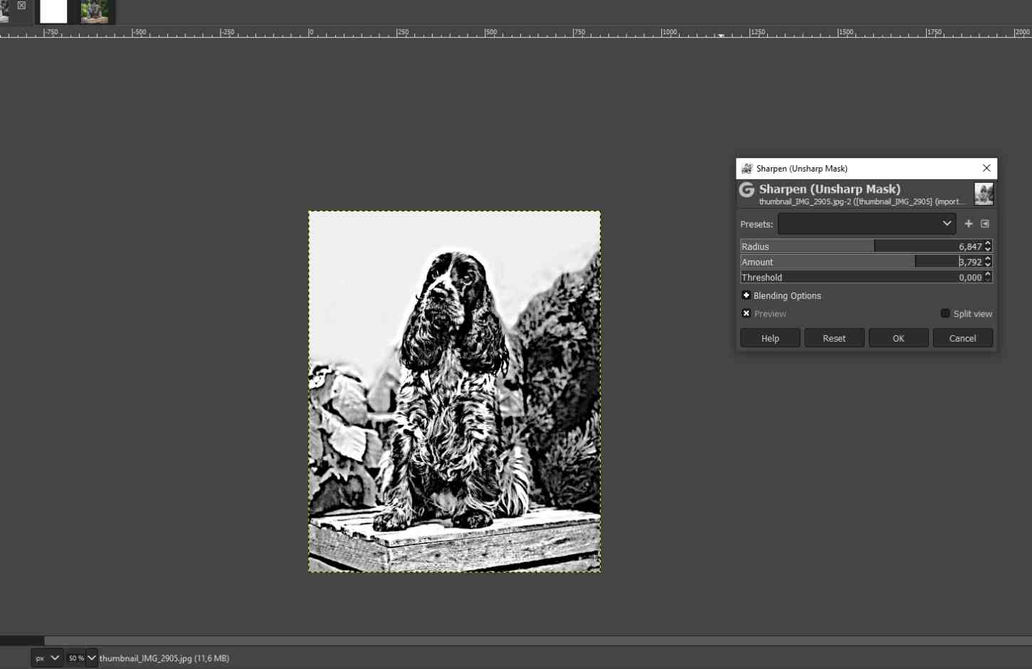
Next, I edited the image to make it clearer for the laser cutter, so first I edited the colours of the image using the Curves Tool: Colors -> Curves. The aim was to lighten the overall look of the image, but also to darken the essential details. I also sharpened the image using the Unsharpen Mask tool: Filters -> Enhance -> Unsharpen Mask. I changed the Radius and the Amount values to test what could possibly be good. The idea was to sharpen the image even perhaps too strongly to make details stand out.
|
|
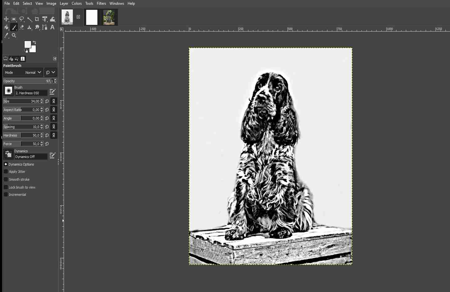
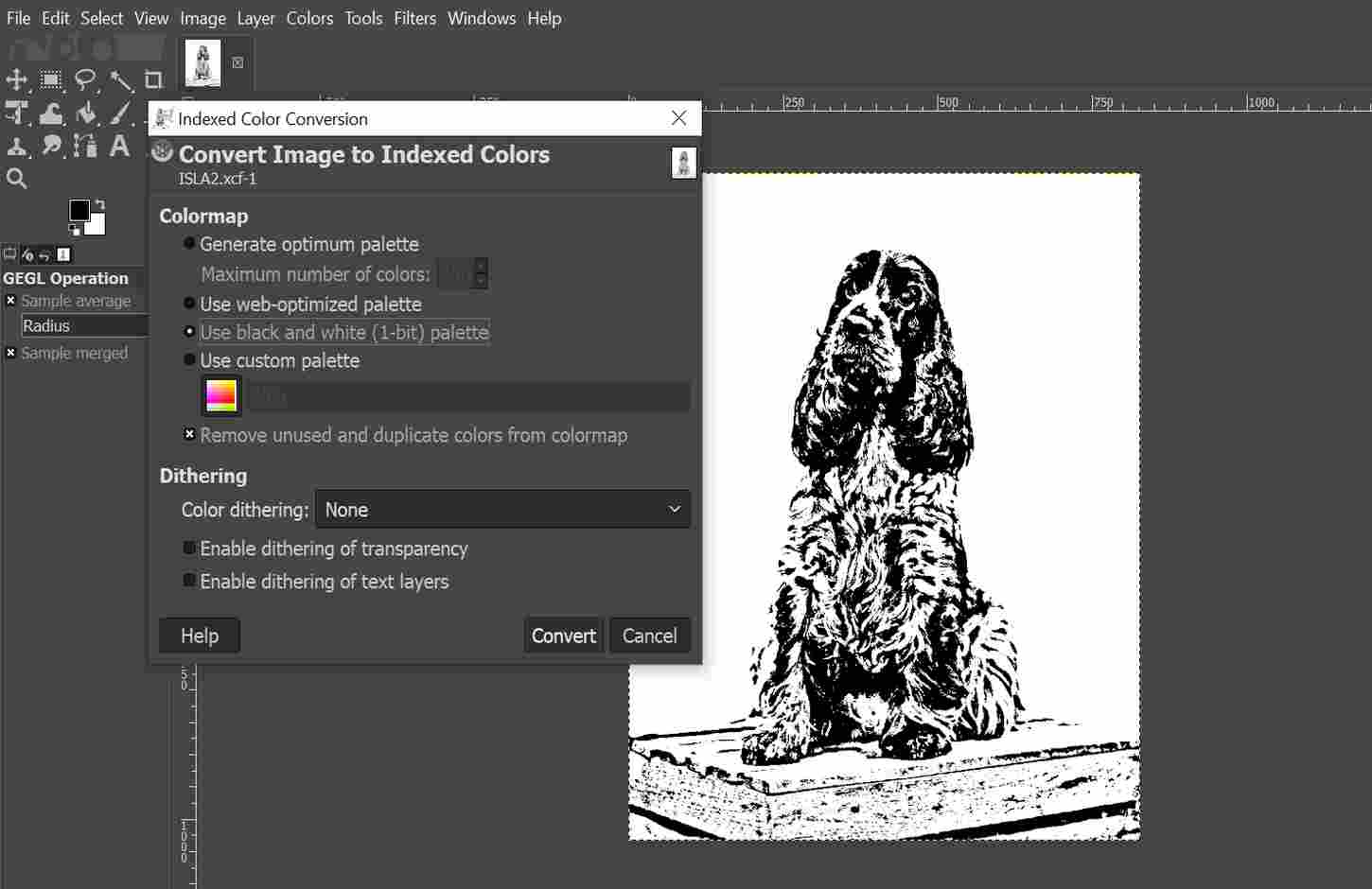
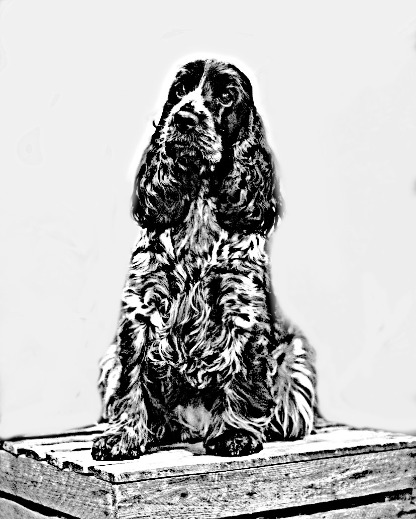
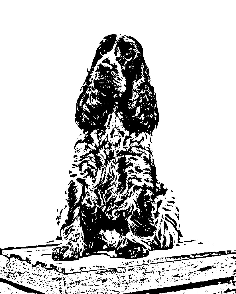
After looking at the image for a while, I wanted to remove all the plants from the background and I did that using the Paintbrush Tool again. This would be one test version for a laser cutter (image below left). I made one more change to the image by converting it to 1-bit: Image -> Mode -> Indexed -> Use black and white (1-bit) palette. This made the image even sharper. I saved this version too (image below right). I had also saved the version with plants, in case I change my mind.
|
|
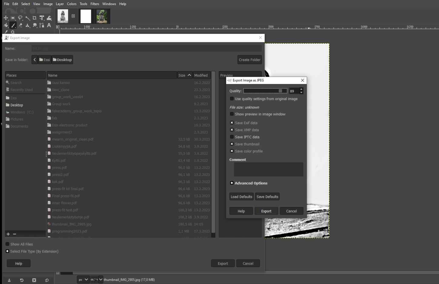
The way I saved the images was to export them as jpg, so I could open them in Inkscape for final edits (image below left).
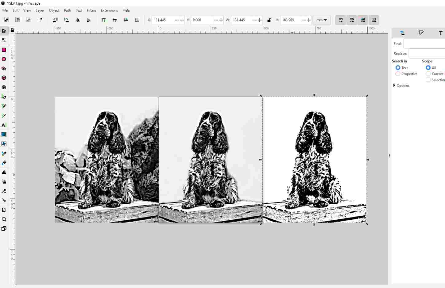
In Inkscape, I opened the jpg, keeping the image size set in Gimp the same. I copied all the versions into the same file, so I could compare them side by side.
|
|
I removed the image with the plants at this point and did a couple of tests with the other two versions to see how well the images worked when lasered.
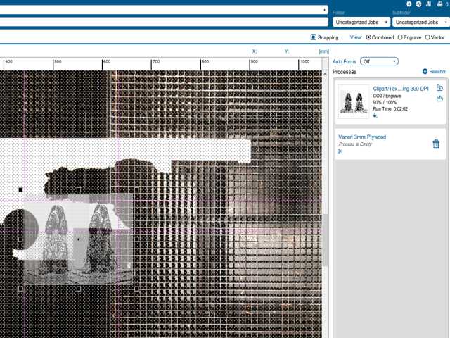
First, I did a little test on the dog's face to see how they stood out. In the laser cutter's print driver (Epilog Dashboard), I limited the engraving area to the area where the dogs' faces are. I used the default settings when engraving on plywood. The engraving settings were: resolution 300, speed 90 % and power 100 %. I also tried engraving with settings where I reduced the power by 50 % and liked this version more because the engravings were not so deep. More instructions on how to use the laser cutter in week 3.
|
|
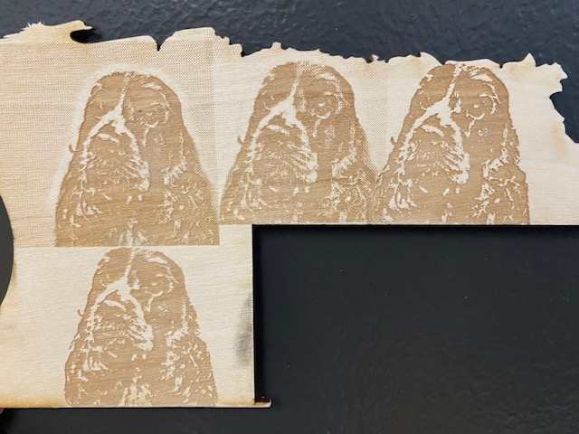
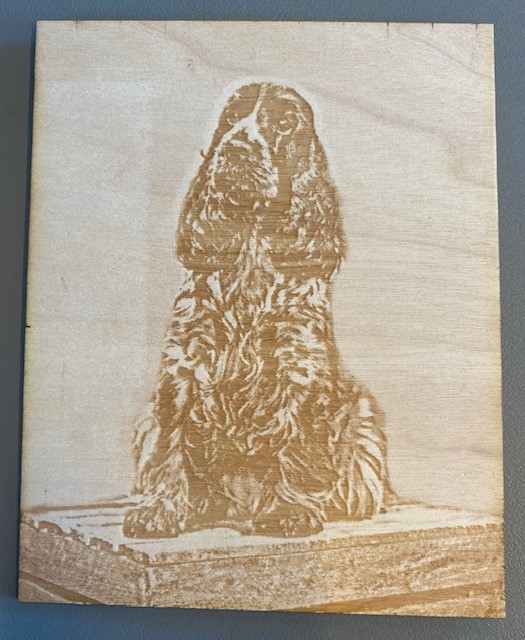
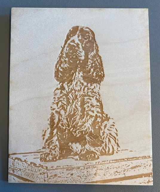
After the test I engraved the whole dog image on plywood in two sides, so on one side I did the engraving without the 1-bit modification (image below left) and on the other side I did the 1-bit version (image below right). I prefer the 1-bit version, although the other one also looks pretty good. There are surely many ways to do this image editing for a laser cutter, but I'm glad with these experiments for now.
|
|
Download JPG file of image (1-bit)
Vector graphic - Inkscape
At first, it was difficult to figure out or actually decide what exactly to model with Inkscape. I wondered whether I should test the design of the bracelet or redraw the idea sketch in digital form. I decided to draw an idea sketch because I've used Inkscape mostly for designing patterns or models for laser cutter and other devices, so the illustrations I was trying to do were more new to me.
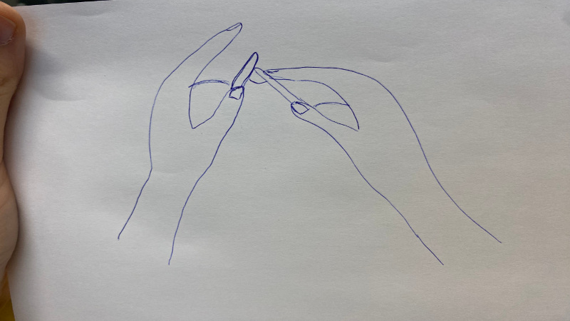
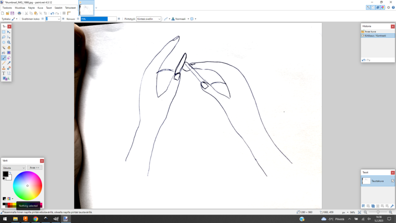
I made a hand-drawn model of the knitting hands, because it would have taken me much more time to draw the hands with Inkscape than to make edits to the hand-drawn ones. I took a picture of the drawing and opened it in paint.net. I changed the contrast and lightness of the picture so that the pencil lines became much clearer, and the shadows and highlights faded away. This makes it easier to trace the picture in Inkscape.
|
|
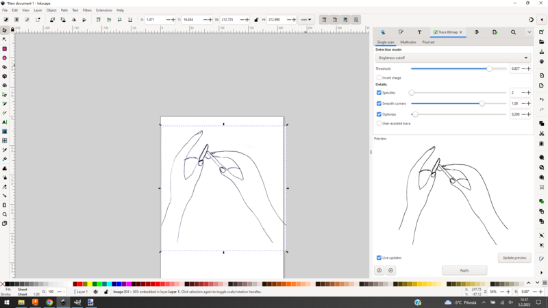
I traced the picture in Inkscape and broke it apart. In the video you can see how I clean up my picture by deleting extra nodes and also editing nodes. I drew new strokes using the bezier tool.
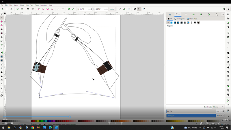
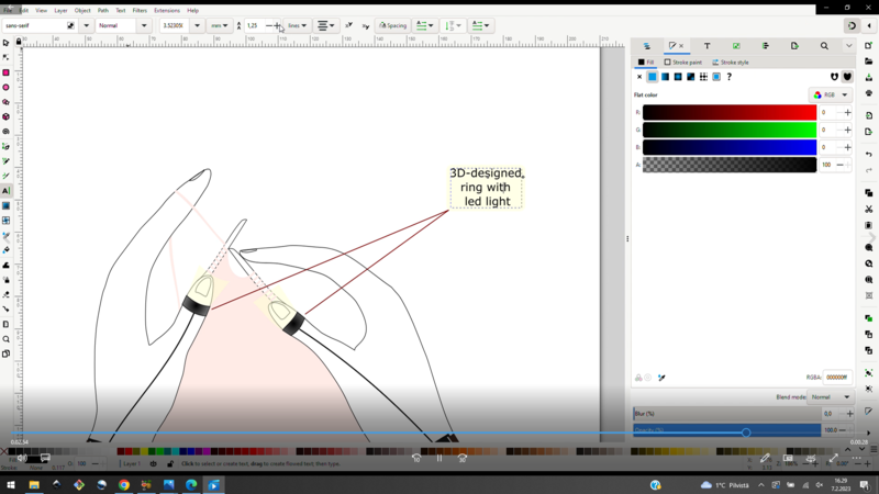
I drew the rings using a bezier tool and put the fill on. The display on the bracelet I drew using the rectangle shape tool. I used the union command when I added the bracelet attachment to the display. I drew the bracelet like a ring using the bezier tool. The knit I also drew using the bezier tool, putting the fill on and placing the knit at the bottom. I also used the bezier tool to make strokes for the text boxes. I changed the style of the stroke to a dashed stroke.
|
|
At first I was wondering how this was going to turn out, but I'm very happy with the result. Picture of the result below:

Download 2D final project sketch
3D design - Fusion 360
I have some previous experience of 3D design in my studies and work, but not so much that I've become familiar with any software. Most recently, I've done a bit of designing at work with Fusion. But only the basics, so now it's time to get more used to using it.
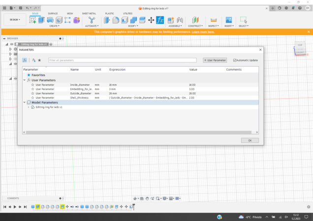
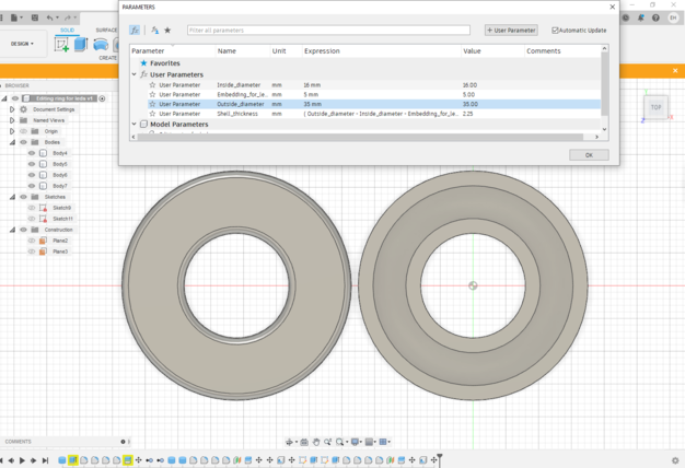
I wrote down some parameters that I could test in my 3D model of the ring. If I remember right, I don't think I've done parametric design before and I think I'm not even close to the core of parametric design as I just wrote down the dimensions. But I checked out the tool! The fourth parameter "Shell_thickness" I wrote later when I tested the shell command.
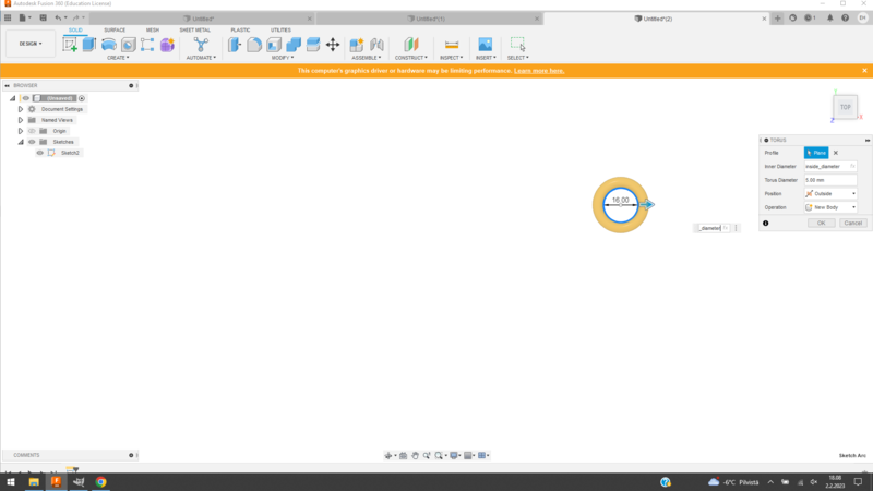
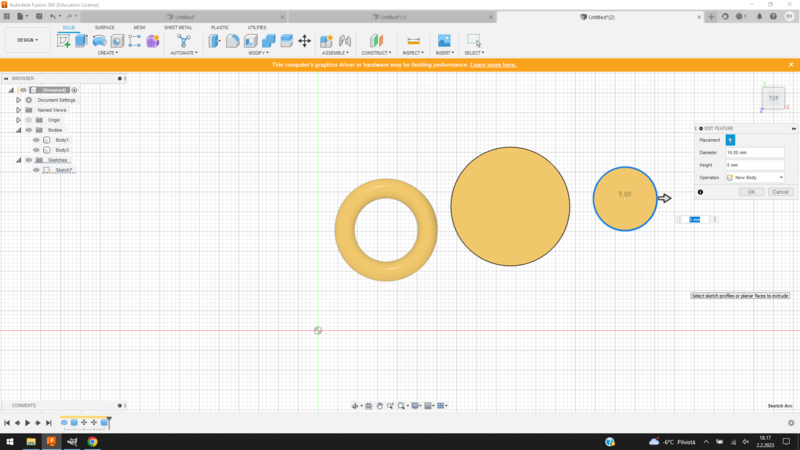
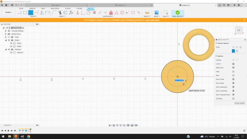
I have no experience in designing a ring, so the first thing I decided to do was to test the possibilities of designing a ring with fusion. In the Create menu I saw the torus and cylinder tools and they looked good for the first tests. I used the parameters to define the dimensions of the bodies and sketches. In the pictures below, on the left is a test of the torus, it was quickly done. When I made the cylinder, I first tried to make two cylinders and cut one with the other, but before I tried to cut, I remembered that our instructor talked about using the origo as a centering point.
|
|
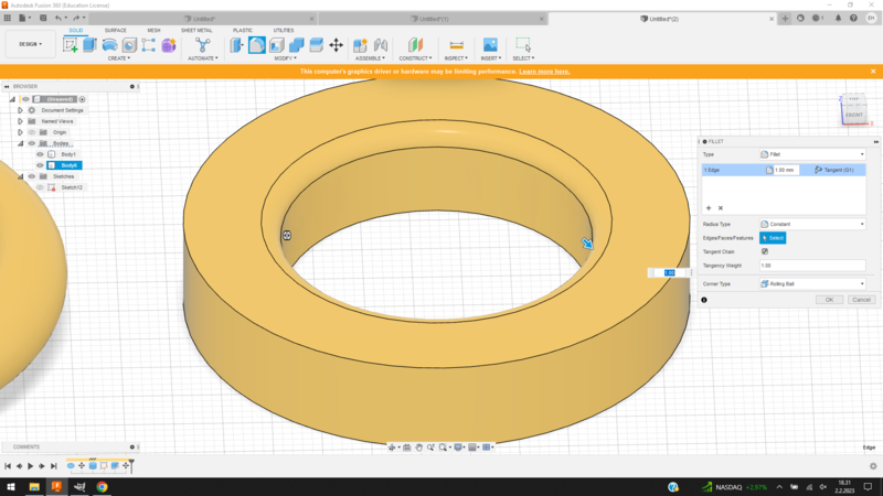
So I made a new cylinder on the origo and again remembered that in a local class we drew a sketch on the face of the body. I created a circular sketch, which I then used the extrude command to cut out the center of the cylinder. The final step at this stage was to round the edges using the fillet command.
|
|
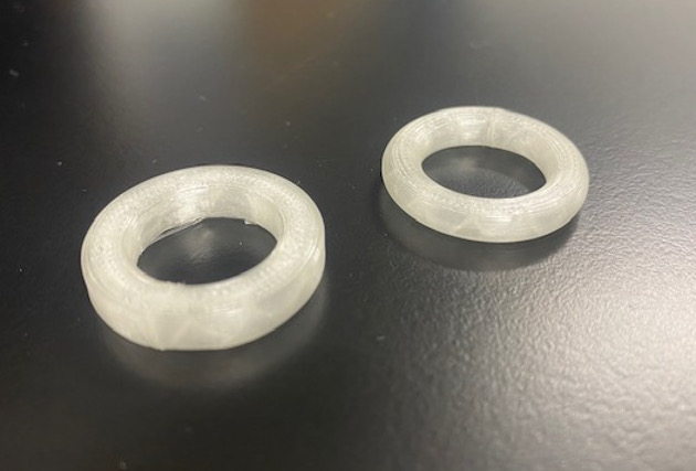
I am a person who likes to touch things, feel them in my hands and observe them as real objects. So of course I wanted to 3D print the first ring tests right away. This is one of the best things about 3D printing, because you can do tests quickly and cheaply. More about 3D printing in week 5.
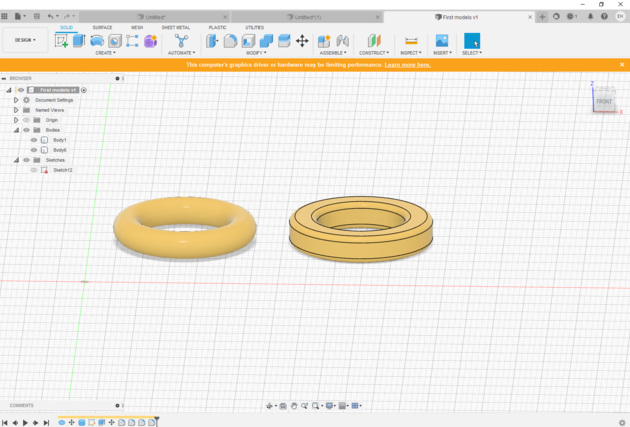
The printing is not the best, but I got the rings to test them. Both felt just fine on my finger. At the moment, the ring made with the cylinder tool looks better to me, so I decided to continue to modify it further.
|
|
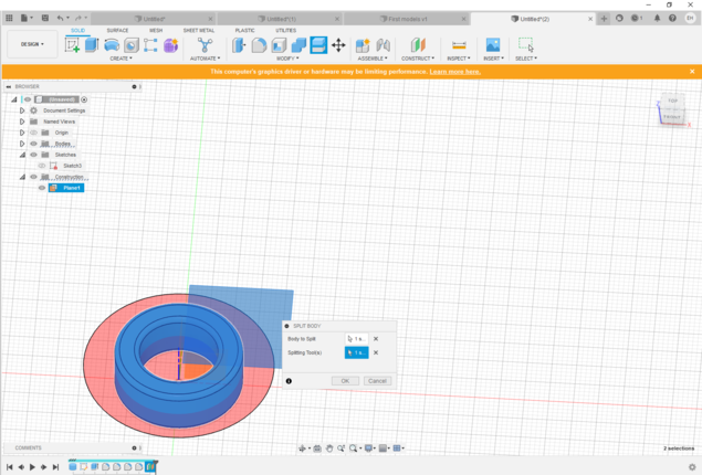
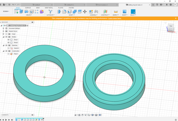
My first test ring was 5 mm width, so next I designed 10 mm width ring to make it easier to modify. I split the body with the split body command and used the construction plane created with the offset plane command as the splitting tool. Then I moved the halves of the ring side by side.
|
|
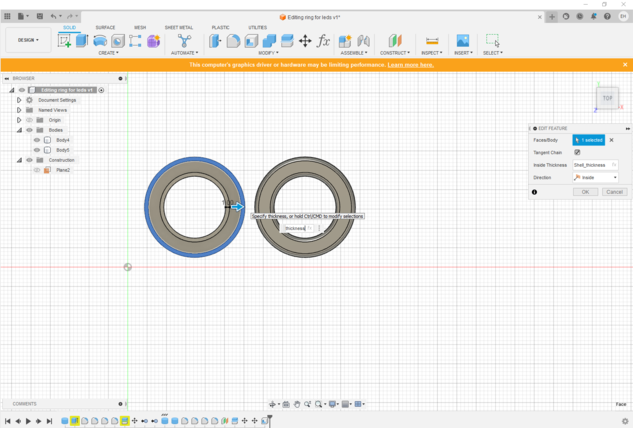
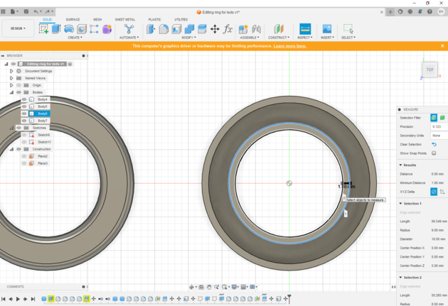
Next, I used the shell command to make a cavity in the other half, which is for the LEDs. Here I used the "shell-thickness" parameter
I developed that determines the thickness of the cavity wall. When I tried to change the parameter values, they did not work correctly for this design.
The cavity became thinner when I changed the size of the ring, even though my understanding is that it should have worked.
For some reason, I didn't stop to think about the problem, but instead jumped straight into testing yet another version of the ring.
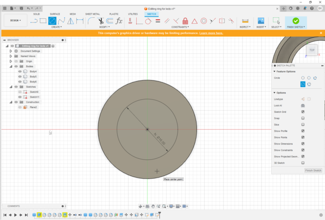
I built the ring from the beginning using circle sketches.
|
|
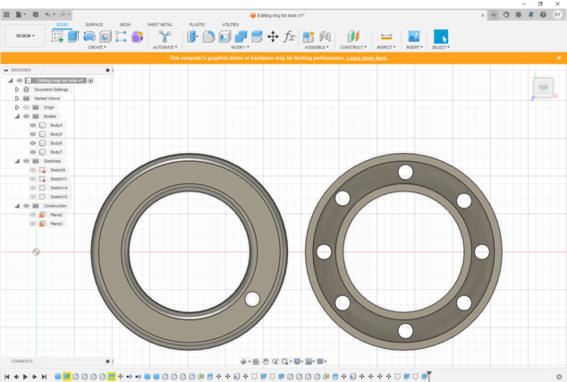
I made the same edits as the previous ring and now, after a shell command, I managed to change the ring's dimensions in the parameters so that the ring still looked right. Great!
|
|
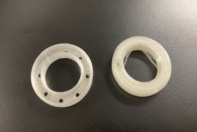
The last step I had time to do now was to add the holes for the LED light and the hole for the wire in the other half. I also wanted to print these, although again the print quality was not the best for this design.
|
|
I tested the rings on my thumbs while knitting, but I couldn't get a picture of the testing for this documentary as I was alone. After these tests, I wonder if the rings even need to be on both thumbs, because possibly the light from one ring can be enough and it's almost easier to have the ring on the left thumb only. The shape of the ring could also be an incomplete circle, which would leave the base of the thumb free and make knitting more comfortable. I had planned the first split ring to be up to 10 mm width, but I think the narrower the better. So these were good first experiments, because I already got some ideas for further development!