5. 3D scanning and printing
Group assignment for this week:
- Test the design rules for your 3D printer(s)
The documentation of group assignment can be found on our group work page.
In group work, we tested the design rules on four different 3D printers. At the same time, we learned about the features and print results of these 3D printers. Previously, I was only familiar with PLA filaments and FDM style printers. The design rules provided good information on what to consider when making different 3D designs.
In many design rules tasks, the quality of the Formlabs Form 3 SLA style printer and resin beat the competition. The negative aspect of the resin printer, in my opinion, is the multi-step process, as the resin print still needs to be washed and hardened in UV oven before it is ready.
Another interesting experience was the Raise 3D Pro 2 FDM style printer with a dual extruder that allows the supports to be made from HIPS material that can be dissolved in Limonene. The printing filament was ABS. This Raise 3D Pro 2 printer also printed well, but if wanted, removing the support in Limonene would take several hours, if not 24 hours. It was also fun to see an older generation industrial FDM style 3D printer Stratasys Fortus 380 mc, that today is beaten by many consumer 3D printers.
Individual assignment for this week:
- Design and 3D print an object (small, few cm3, limited by printer time) that could not be easily made subtractively
- 3D scan an object (and optionally print it)
3D printing
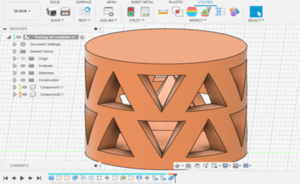
I didn't have anything specific in mind for 3D design, so I started watching Youtube videos and finding something new to learn about Fusion while trying to solve the task of 3D design and printing something that could not be made subtractively. I found this video and used its lessons about emboss and patterns tools to start designing something with the idea of "parts within parts". When there is a pyramid inside the cylinder and the mantle of the cylinder is decorated with triangular cuts, I don't think it would be possible to make this subtractively. Or at least it would take time to achieve the same result.
Design with Fusion 360
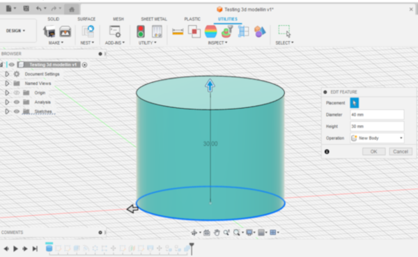
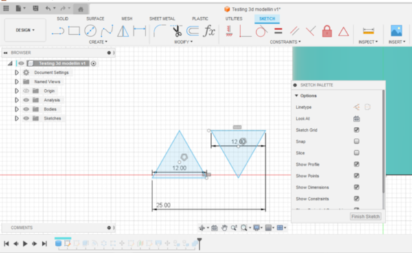
First in Fusion 360 I created a new body with cylinder tool. Left picture below. Second, I created a sketch for embossing. I calculated the circumference of the cylinder and designed the dimensions of the pattern as a seamless pattern according to the circumference. For this pattern I simply used the shape of a triangle (Create sketch -> Edge Polygon). The angles of an equilateral triangle are 60 degrees, so the overhang we tested in our group work still works. With the same type of printer, after 60 degrees the quality of the overhang started to decline. Right picture below.
|
|
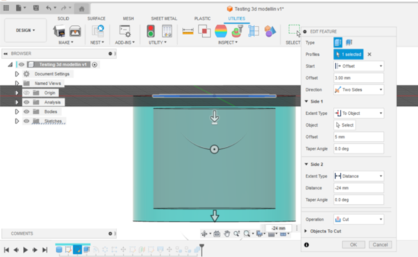
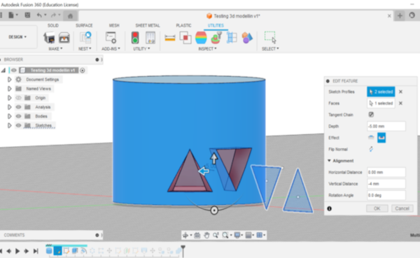
I created center diameter circle sketch to top face of cylinder and cut out the inside of the cylinder with extrude tool. Left picture below. Next, I used the emboss tool and chose triangles as the sketch profiles and a mantle of the cylinder as the face. I chose deboss as the effect, so the triangles were cut out of the surface. Right picture below.
|
|
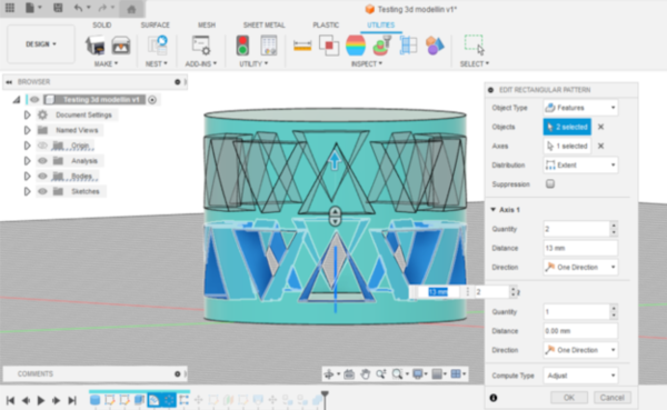
The seamless pattern was easy to make by applying circular and rectangular patterns to emboss. First, for circular pattern, I chose features as the object type and chose triangles as the objects. For the axis I chose the z-axis. The quantity in this pattern was 5. Second, I made rectangular pattern and chose all the triangles as objects. I calculated and tested the distance for the upper row and 13 mm from the bottom of the first row of triangles was good. Left picture below.
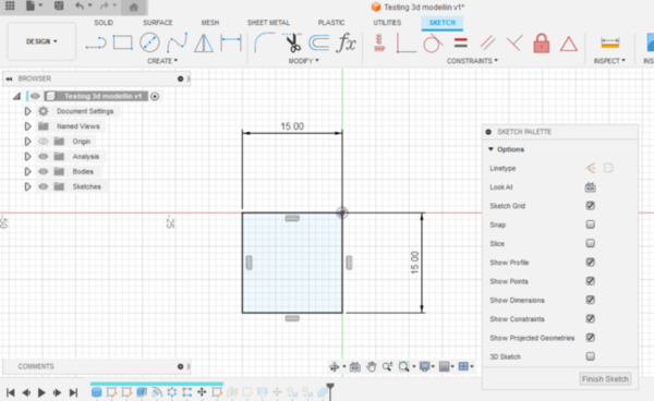
Because I used triangles for embossing, I decided to make a pyramid as an part inside the cylinder.I had not made a pyramid with Fusion before, so I looked for instructions in tutorials. I found a very easy way to create a pyramid using the sketch, construct plane and loft tools. First, I created a square sketch with 15 mm sides. Right picture below.
|
|
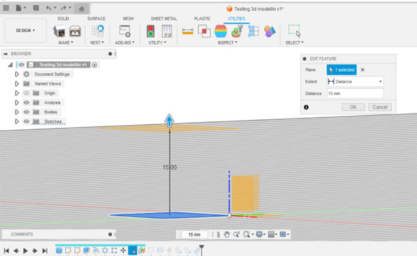
Next I made an offset plane 15 mm high from the squre sketch. Then I created a new sketch using the offset plane and added only a point in the middle of the square. Left picture below.
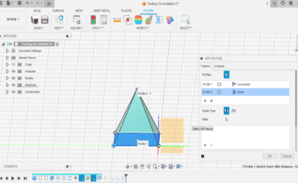
Now I had the square and the top point of the pyramid, so I used the loft tool to complete the pyramid. I simply selected the square and the point and created the pyramid. Easy! Right picture below.
|
|
As a final step in the design, I moved the pyramid inside the cylinder and placed it in a way that I could build a support material under the pyramid. I combined the cylinder and the pyramid into one component using the combine tool. Picture below left.
I saved STL file of the design in the following way: Utilities -> Make -> 3D Print.
3D printing
We have two types of FDM style 3D printers at the BusinessAsema Fab Lab. I wanted to use our Sindoh Wox dp201 printer for this print just because of its 3DWOX slicer. In my experience in 3DWOX slicer it is easier to edit the support the way I want. I only want to make the support under the pyramid, so it won't stick to the cylinder and the small support might also be easy to get out of the cylinder.
I used PLA filament for printing. The settings I set in the 3DWOX slicer:
- Layer Height 0.15 mm
- Support everywhere, infill dencity 20 %
- None Bed Adhesion
- Infill pattern automatic, infill density 20 %
All other settings were default, e.g. nozzle temperature was 200, bed temperature 60, flow 100 % and print speed 35 %.
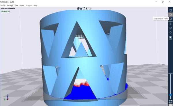
I wanted to make my own supports just under the pyramid, not completely inside the cylinder, so I edited the supports in the Support edit viewer (the second icon in the top right corner of the 3DWOX slicer). First I right-clicked to delete all supports and then I used the slider at the bottom right to move the level to the right under the pyramid, hitting the inner bottom of the cylinder. Then by left clicking I was able to build a new support. The support could also be deleted by pressing CTRL on the bottom and left-clicking. Picture below left. If I had kept the automatic support on, the cylinder would of course have been fully supported. However, it would be quite a job to get all the support out through the triangular shaped holes, so this is a test to see how the model works without support.
When I was finished with the support, I generated the G-code by pressing the third top icon in the top right corner (Layer Viewer). Our Sindoh 3D printers are connected to computers via wifi. So next I just selected My Printers from the Printer menu and selected the printer I wanted to use. Finally I pressed the Print icon on the toolbar on the right and I was able to send the file to a 3D printer.
|
|
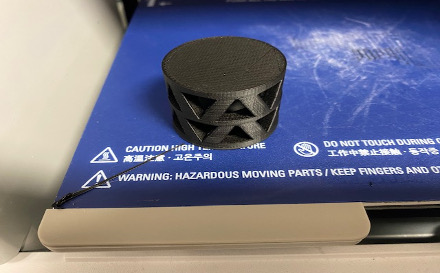
Once the file is sent to the 3D printer, the printer starts to heat up the bed and nozzle. It usually takes a few minutes to adjust the temperature. The estimated time for printing was about 2 hours.
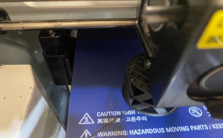
I checked the print from time to time, and it looked pretty good. In the picture below left can be seen a little bit of the infill building up inside. When the print was ready, the bed settled down and cooled down. Picture below right. The print could be easily removed by hand. It took about 2 hours to print, which was the estimate.
|
|
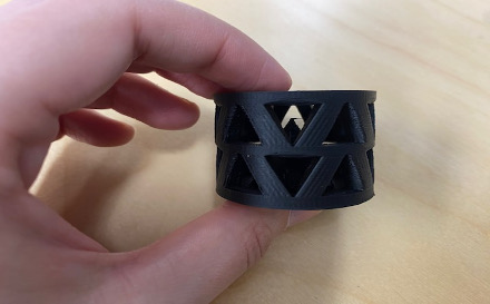
Now I could see what had really happened. What excited me the most was how the inner roof of the cylinder would work, whether the bridge would be too long to succeed. It was difficult to get a picture of the inner roof, but it was successful, a little sagging can be seen, but it seems to be very durable. The inner roof was a diameter of 30 mm and in our group work the longest bridge we tested was 25 mm. On a printer of the same type, the bridging had worked well, so I took a risk by printing with 30 mm bridging. For future testing, here is an example of a template for testing longer bridging.
The vertically oriented sides of the triangles were also slightly sagging, although they are quite short in length, about a centimetre. But I don't think it looks too bad. In the picture below left, you can see a bit of stringing on the top of the pyramid, but that didn't matter in this printing either.
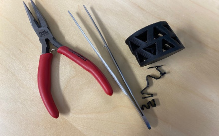
So printing without the support material filling the whole cylinder worked just fine! There would have also been a 3D printer at the Fab Lab Oulu that could use HIPS support material, which can be dissolved with Limonene, so a cylinder full of support would also be easier to make. I was able to remove the support under the pyramid surprisingly easily using pliers and tweezers, although the small triangular shaped holes created their own challenge. Picture below right.
|
|
I'm glad with this experiment and was wondering if I could try something similar in the shape of a ball, so the result could be used as a cat toy... Probably the ball shape can bring new challenges to the design and printing, but it would be interesting to try.
Download F3D file for 3D printing test
Download STL file for 3D printing test
3D scanning
This was my first time to try 3D scanning and it felt both exciting but also a bit terrifying, because I haven't heard very good experiences with it. The scanner I used was Shining 3D Einstar 3D scanner, which we have in our Fab Lab at BusinessAsema. Einstar is an affordable handheld 3D scanner, that collects high density point cloud data fast and easily with point distance up to 0.1mm, benefits from built-in RGB color camera, builds 3D data with authentic colors and is easy to use (source for the description on Einstar website).
I watched this review video on youtube for tips on using the scanner and its software.
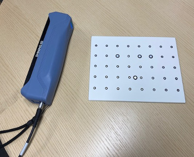
The scanner software is EXStar, which was really easy learn to use. The very first thing I did was to calibrate the scanner. The software has really good instructions for calibration and it also tells you when the last calibration was done. The scanner comes with a calibration plate for calibration. Picture below left.
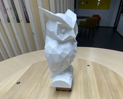
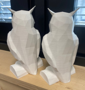
I tried to scan a 3D printed owl. It was big enough for a first try, but it also had some interesting surfaces to test. I placed the owl on the rotating tray, so that I could use the tray when scanning.
|
|
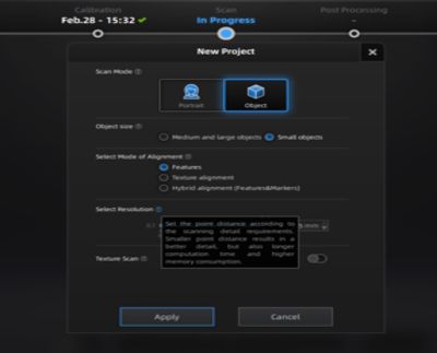
I created a new project group and named it. There is two options to scan mode, Potrait and Object, and in this case I chose Object. For the object size I selected small and for the mode of alignment I selected Features. For the resolution I selected 0.2 high quality and I took the texture scan off. Picture below left. I chose these settings really just as an experiment, and for tips I watched the video I mentioned above.
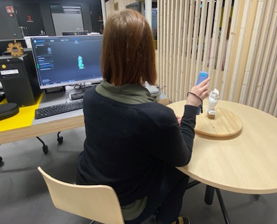
Then I started scanning. During the scan, all you have to do is use the scanner itself, it has a few buttons on the back that allow you to scan and change its settings. In its simplicity, scanning starts and stops with a button in the middle, and other buttons let you change the brightness and zoom. I rested my elbow on the table and held the scanner in one place, just moving the rotating tray at first. Picture below right. In the video the man is scanning quite bravely while moving, so I tried that too, but there's a risk of tracking lost, but it's pretty easy to get it back.
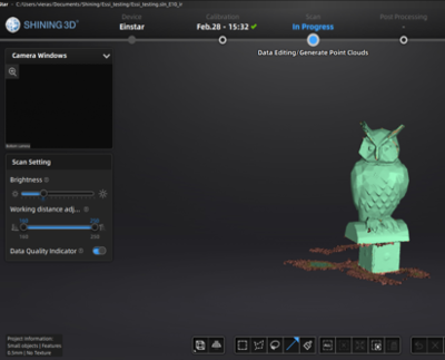
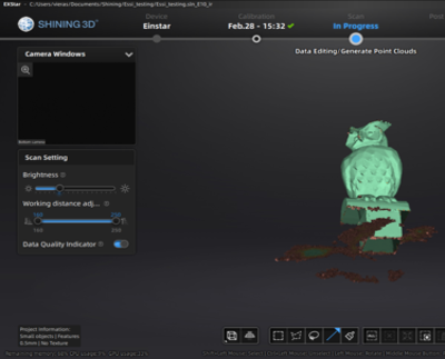
On the screen you can see the scan settings, whether the scan is too close or too far away, the scanner's camera window and in the middle of the screen you can see the result of the scan at that moment.
|
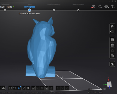
|
Scanning in the progress. The color of the scanning mesh change from red to green, when the software thinks that there is enough data points to get a good scan. I made few scanning in the same project and got the results which are seen in pictures below. Pretty green, isn't it! Some parts, like the bottom of the belly or the top of the head or the tips of the ears, were difficult, but otherwise, little by little, the scan was successful.
|
|
Next, I edited the data. I selected lasso from the toolbar at the bottom, pressed shift and made a small selection in the data below the owl that I wanted to remove. Then I selected the cutting plane tool from the toolbar and used the selection area to create a cutting plane. I moved the cutting plane to the good position and used the cutting plane to remove selected data below the owl. I also used lasso tool to removed the data which was hanging in the air.
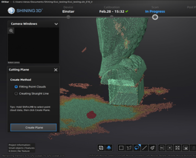
|
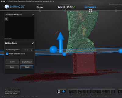
|
In the pictures below I have generated the point cloud. This was done simply by pressing the second highest button on the toolbar on the right side of the software. There are two options to generating point cloud, with or without optimizing. I had already cleaned up the data, so I generated point cloud without optimizing. The point cloud looked pretty good, there were no big holes in the model, etc.
|
|
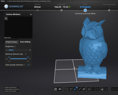
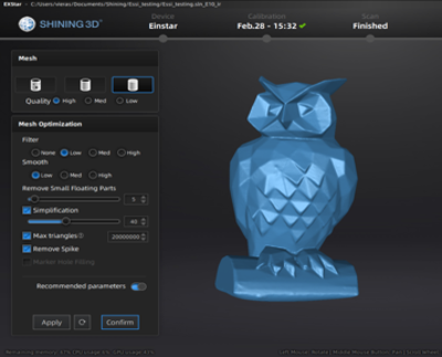
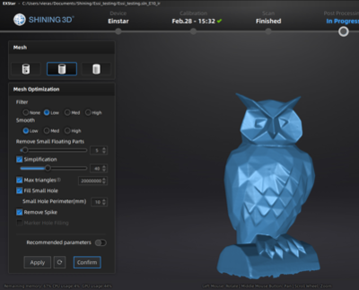
Next, I meshed the model. This was also easily done in the same software by pressing the bottom "Mesh Model" button in the toolbar on the right side of the software. I tried two options: the watertight, which is in picture below left and the semi-watertight, which is in the picture below right. I chose the semi-watertight mesh for next editing. Otherwise, I tested the settings a bit and chose some by default, as I have no previous experience with meshing or this software. I confirmed the settings and it took a couple of minutes for the software to meshed the data.
|
|
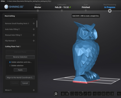
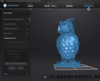
The next step is the mesh editing page, which I didn't get to know much about at this point. But on a quick look, there are many editing options, presented for example in the video I mentioned. I noticed that I was able to use the cutting plane tool here as well, which allowed me to make a clean and straight base for the owl, great! Now the owl looked ready for a printing test, wow! I saved the file in STL format. The "Save Your Scan" button can also be found in the toolbar on the right side of the software, second to the top button.
|
|
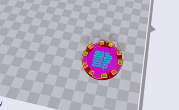
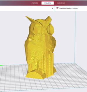
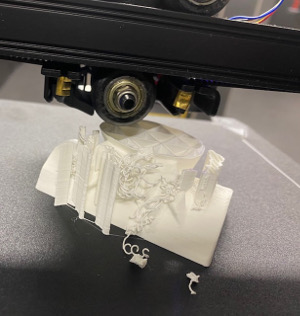
To 3D print this owl, I used Creality Ender-3 V2 Neo 3D printer and Creality Slicer. Automatic support partially failed right from the start, but otherwise printing seemed to work. I didn't know how to use this slicer to edit the support (and I'm not sure how possible it is), but the only thing that really needed support was the owl's beak, everything else was unnecessary.
|
|
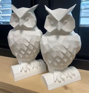
Wow, printing was a success! I'm surprised, maybe this was just beginner's luck. Scanning was unexpectedly inspiring, although I was a bit sceptical at first. Scanned version in the pictures below on the right, original version on the left. The main difference is that the scanned version is smoother than the original, with less sharp details. I could say I liked this scanning experience, but I would have to scan more to really get the most out of this scanner.
|
|