9. Output devices
Group assignment for this week:
- Measure the power consumption of an output device
The documentation of group assignment can be found on our group work page.
In our group work we measured the power draw of two different displays, OLED display 0.96 inch 128x64 and LCD display 4x20 and calculated the power consumption of a few different options. We first measured the power draw of the display alone, using only a breadboard and a multimeter. The multimeter was connected between the 3.3 V VCC line and the VCC connector on the display. In the end, we also tested the usb power meter we got from the local instructor, which allowed us to measure the overall consumption using the LCD display (backlight on). The overall consumption using the OLED display was too low to be measured with this usb power meter.
When comparing the power consumption of an OLED display and an LCD display without backlight, the difference was not very big - OLED 0.014 W, LCD backlight off 0.05 W. It's worth noting that the LCD display was a bit larger than the OLED display. The main finding was that the LCD display backlight consumes significantly more amount of power compared to not having the backlight on. When the backlight was off, the power consumption was 0.05 W, while when the backlight was on, the power consumption was 0.29 W.
This group work was good for the future, as I had more time to plan and test the final project. I was thinking of possibly using an OLED display, so it was good to learn how to measure power draw and calculate power consumption.
Individual assignment for this week:
- Add an output device to a microcontroller board you've designed and program it to do something
Output device - OLED display
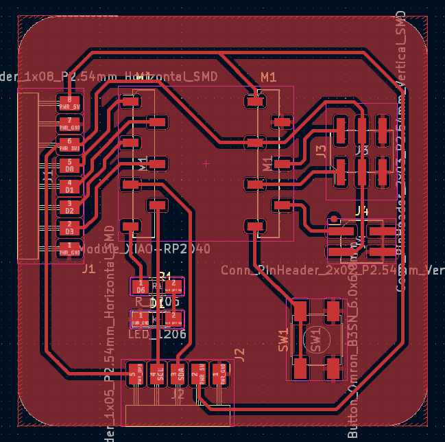
For this week's individual assignment, I used the development board I designed in week 6 and made in week 8. I also used the lessons learned in week 4 for programming with the arduino IDE.
I first tested the OLED display which I borrowed from our local instructor. I connected the OLED display's Vin, GND, SCL and SDA pins to my development board by using jump wires. In OLED display is clearly marked which pin is which and from the drawing of my PCB I was able to check where I was connecting them. The four pins in use can be found at the bottom of the board on the 5-head pin connector. The power was 3.3 V. Picture below.
The OLED display uses the I2C communication protocol. I2C uses only two bidirectional open-collector or open-drain wires: the serial data wire (SDA) and the serial clock wire (SCL), which are pulled up by resistors. I don't have these resistors on my development board, but these can be found on the OLED display.
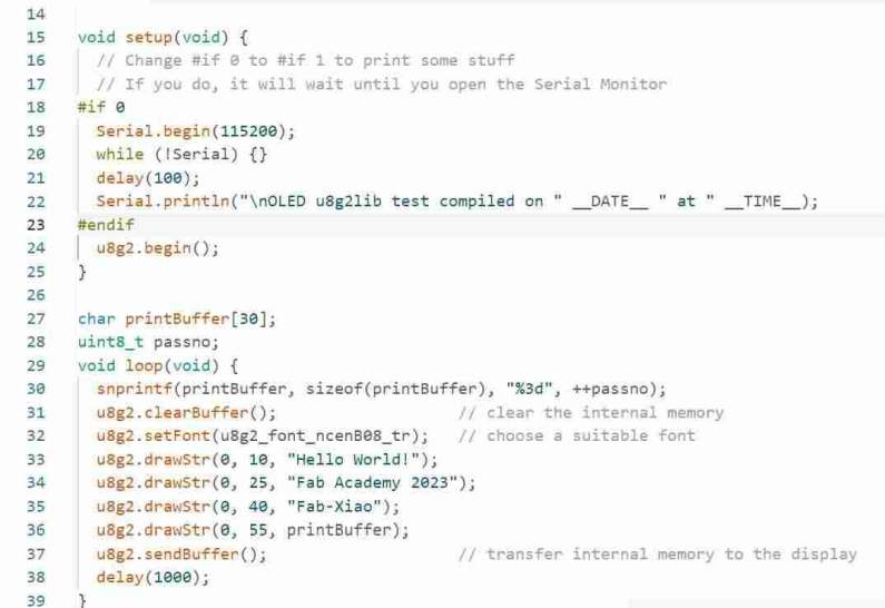
For programming the display, I looked for tips on Adrián Torres' and Random nerd tutorials websites. First, following the instructions on those pages, I downloaded Adafruit_SSD1306 library and u8g2 graphic library for Arduino IDE.
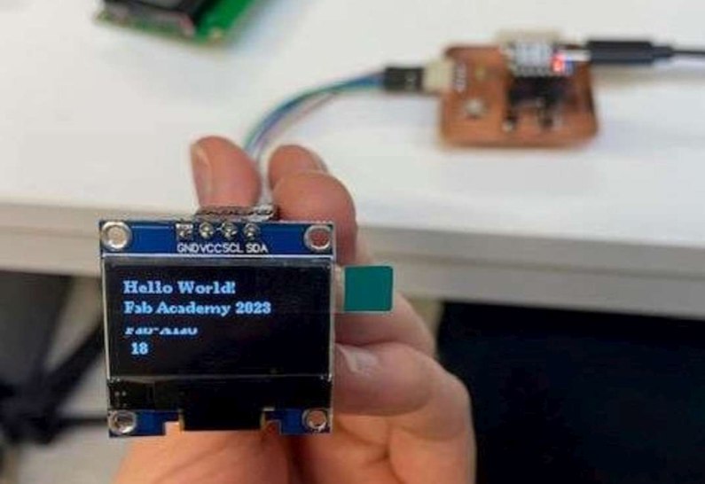
After downloading the libraries I used the test code from Adrián's instructions and uploaded it to the board. The display and code worked on the first try, wow:
|
|
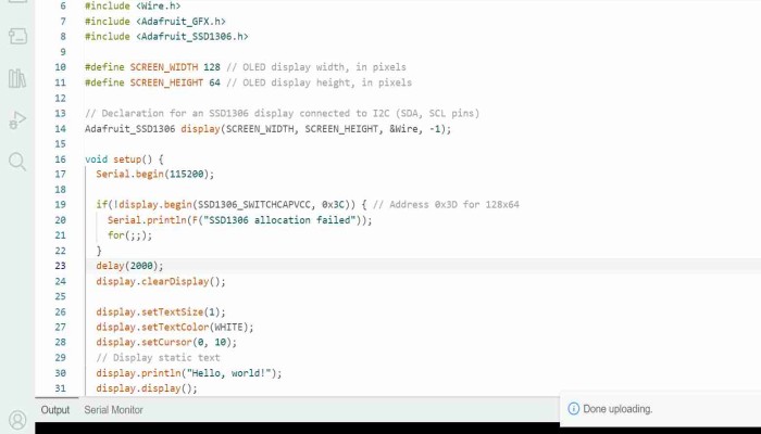
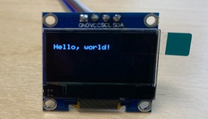
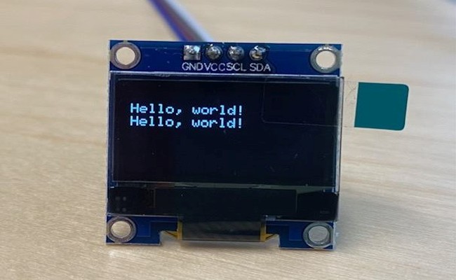
I also tested the "Hello world!" code from Random nerd tutorials website and it worked:
|
|
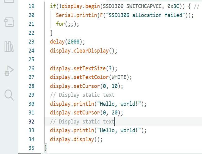
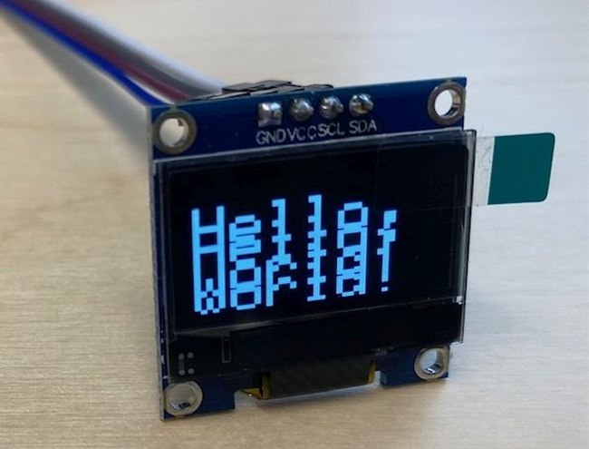
I tried to change text size and add second row, but text size was too big, oops:
|
|
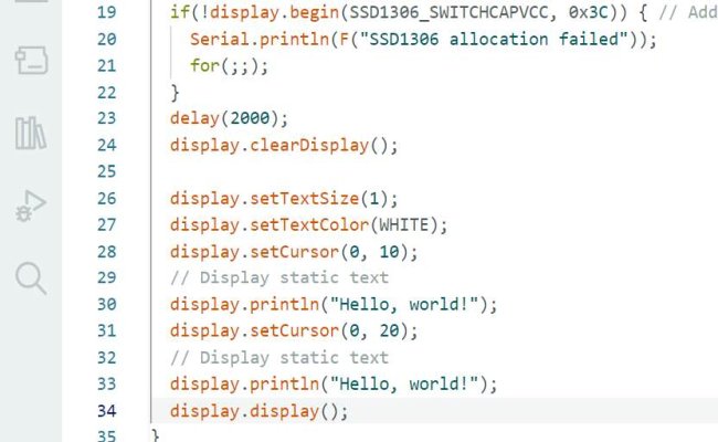
Smaller text size and it worked:
|
|
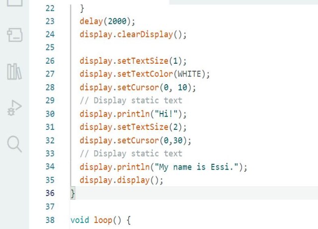
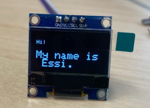
Added two different font size, there is quite a big difference between them:
|
|
Here were the OLED tests for this week. There will surely be more work with OLED for the final project.
Download Ardian's modified code for OLED TXT file
Download Random nerd tutorials code for OLED TXT file
Download "Oops, too big font size" code for OLED TXT file