8. Electronics production
Group assignment for this week:
- Characterize the design rules for your in-house PCB production process
The documentation of group assignment can be found on our group work page.
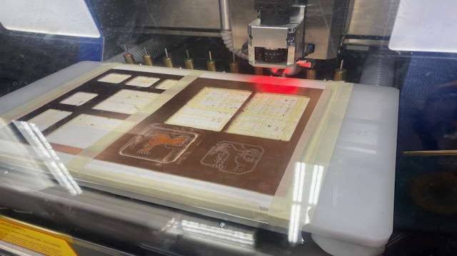
In this week's group work, we practiced using Roland SMR-20 milling machine to mill boards. For milling we used the test files provided by our instructor (traces and interior). First, we used MODS to create RML files for milling. MODS has many steps to create the files, so the good documentation on our group work page is very useful.
Milling boards with the Roland SMR-20 requires some more steps than the LPKF milling machine we used for our individual assignments. With the Roland, it is best to use small pieces of board material, as this will help to ensure that the material securely and evenly attached to the sacrificial board. To get a good milling result when milling with the Roland, you may need to mill several times to get deep and precise tracks. This is affected by the evenness of the board and also by the use of a v-carve bit. At the beginning of the local lesson we were told how to use the v-carve bits, the different bit tip angles and how to calculate the correct milling depth. In our group work, we managed to get a pretty good result on the first go.
Individual assignment for this week:
- Make and test the development board that you designed to interact and communicate with an embedded microcontroller
Generating Gerber files in KiCad
For the individual assignment I used LPKF milling machine, so for milling we made Gerber files in Kicad. I had designed the PCB in week 6. I opened the PCB design in Kicad PCB editor and navigated to File -> Plot.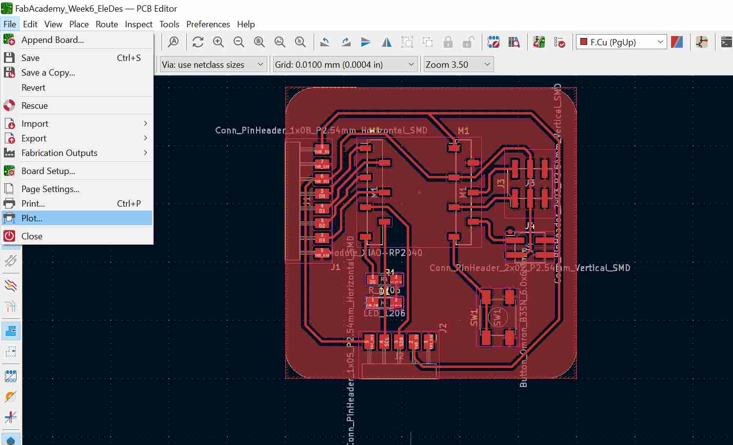
Settings we used in the picture below left. Once you have selected the settings, just press "Plot" and the Gerber files will be saved in the project folder. I copied the saved files to a memory stick. Picture below right.

|
|
Download the Edge Cuts Gerber file
LPFK CircuitPro and milling
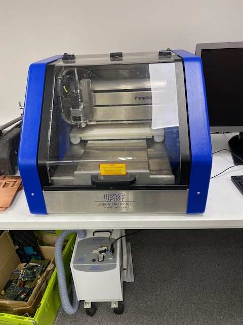
The LPKF milling machine we used is shown in the picture below. There is an air management system under the table and you should check that it is turned on when you start working.
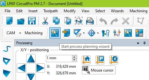
I opened a new project on the computer in LPKF Circuit Pro program.
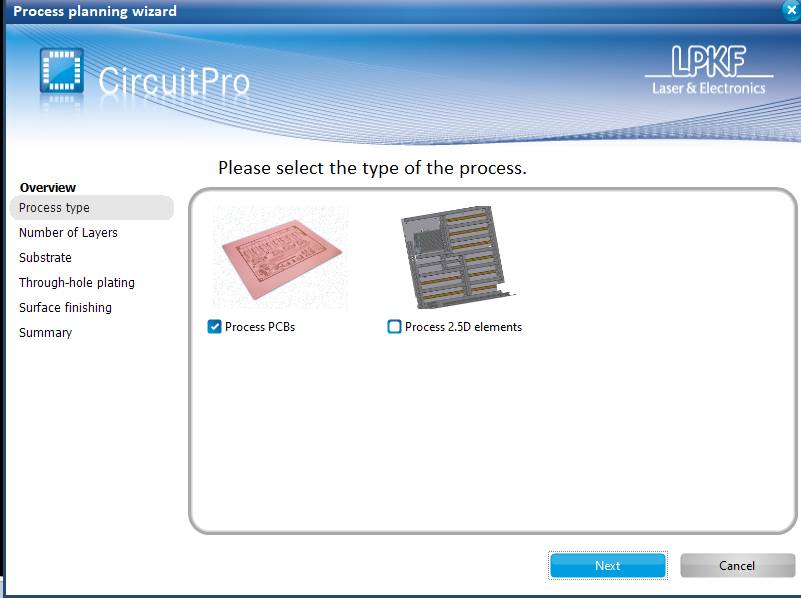
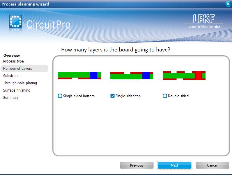
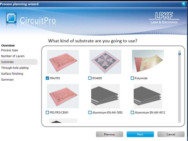
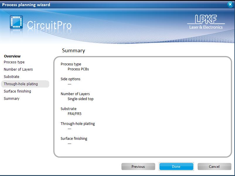
It was easy to set up the project by going through the buttons at the top. First step was "Start process planning wizard":
The settings for the first step are in the following four pictures:
|
|
|
|
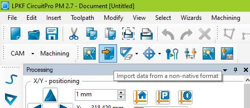
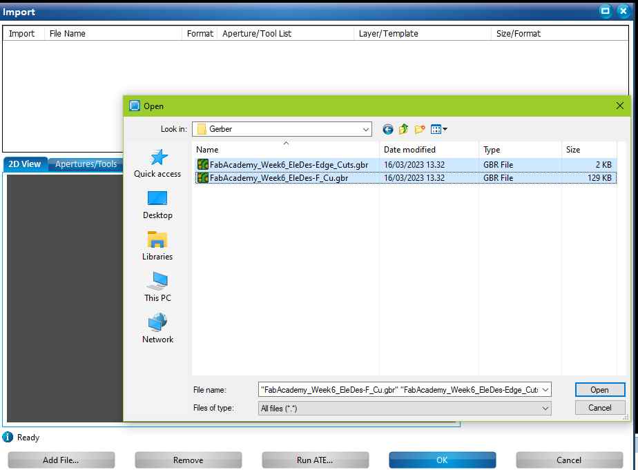
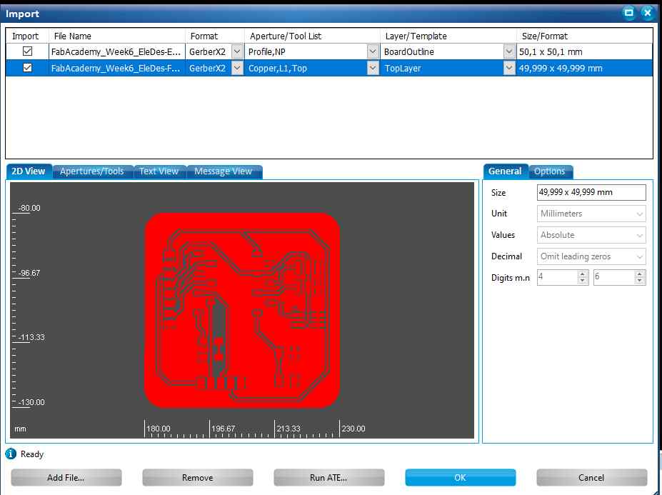
Second step "Import data from a non-native format":
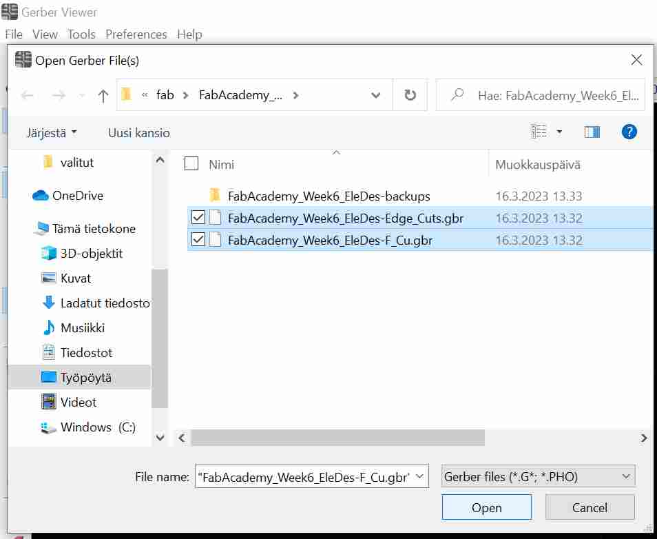
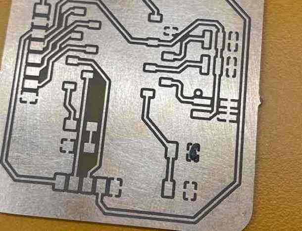
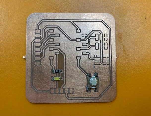
I opened the Gerber files from the memory stick and checked them in the preview. There is two processes, milling the top layer and the board outline.
|
|
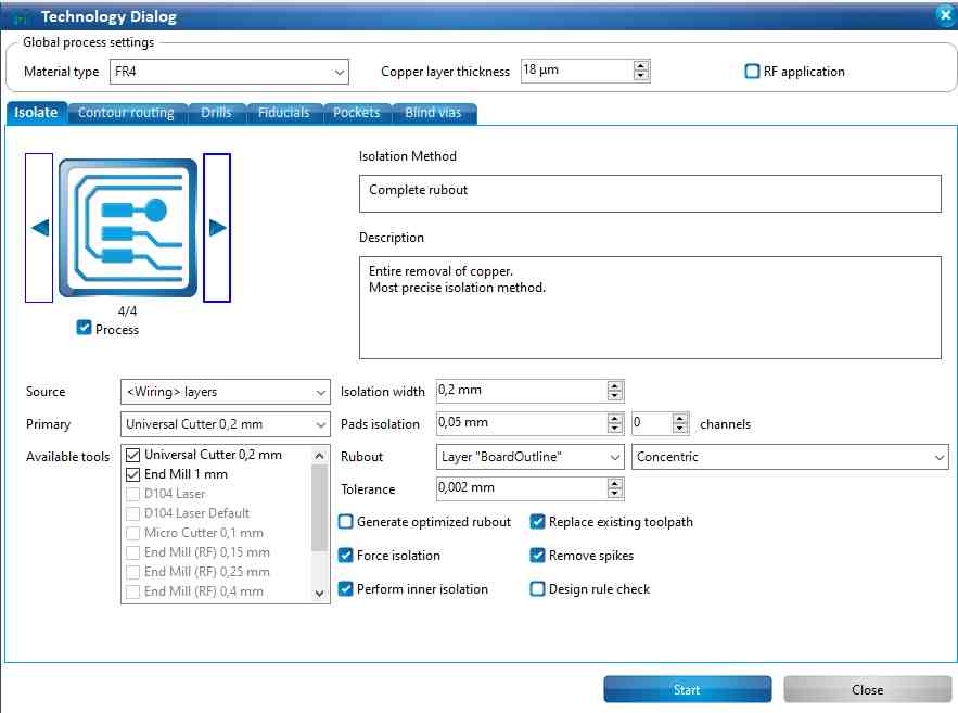
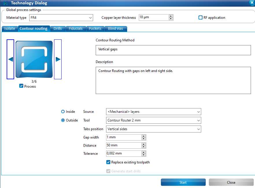
I skipped a couple of buttons because I didn't need them for this project and the third step was "Generate isolation and contour routing toolpath".

The settings for the third step:
|
|
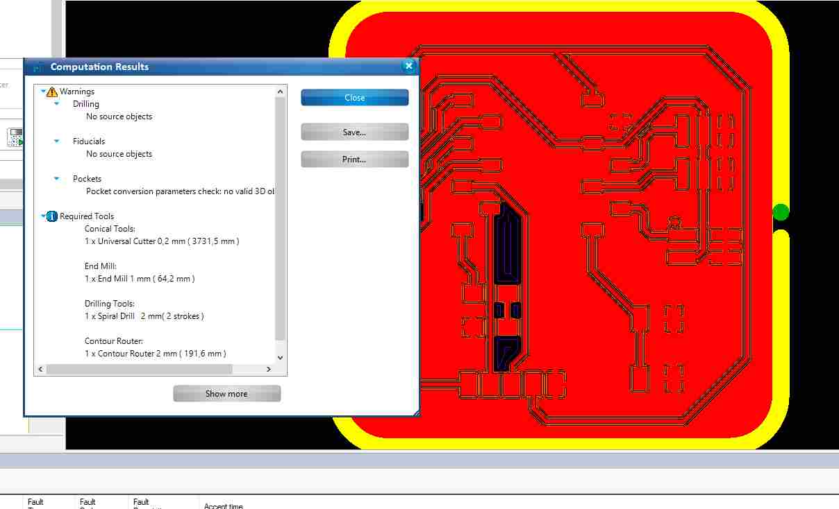
In the end of this step came computation results. I checked them and closed the window. Picture below.
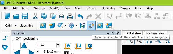
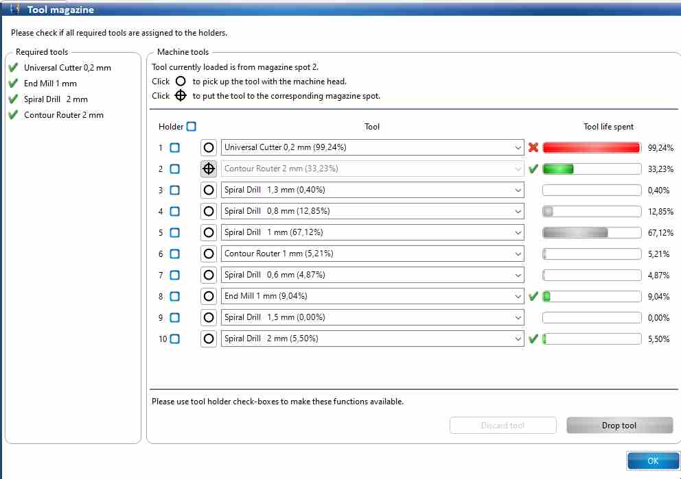
The fourth step was "Open the dialog to edit the contents of the tool magazine":
I checked the tool magazine and the required tools. The "Universal Cutter 0,2 mm" tool was almost at the end of its life, but it worked well in the previous project, so I dared to continue with it. The machine tracks the life of each tool according to its use, which is a really good thing.
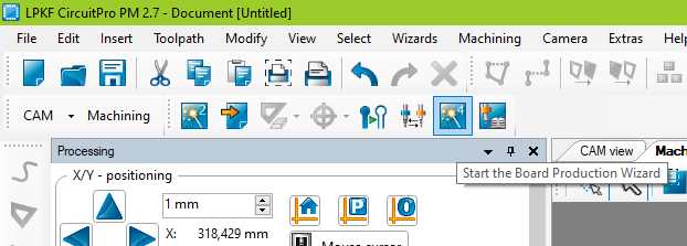
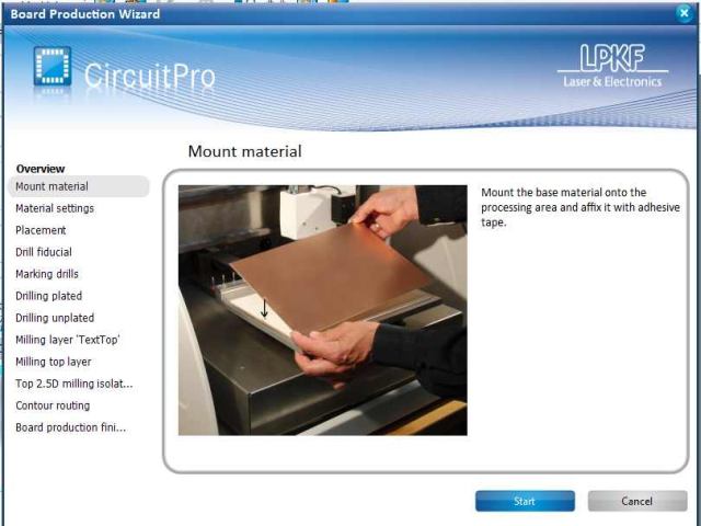
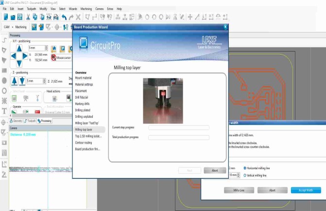
The fifth step was "Start the Board Production Wizard":
The Circuit Pro software also had instructions (picture below left), but our instructor showed us how to mount the board on the processing area. It is important to check that there is nothing under the board before mounting the board. The processing area can be vacuumed. The board was taped onto the processing area. Picture below right.
|
|
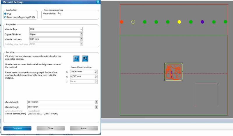
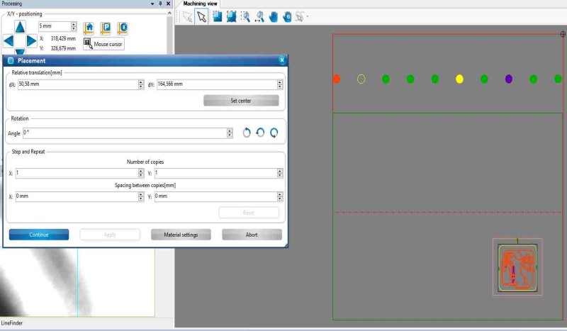
Next, in fifth step, under Material settings I set the location of the board milling. First, I clicked on the area near where I wanted the bottom left corner to be. For fine adjustment, I used the arrows in the program. When I found the right place for the bottom left corner, I pressed P1 to have it there. Next, I placed the top right corner and pressed P2 there. Picture below left.
I placed my PCB-design inside the area and pressed continue. Picture below right.
|
|
I made a little milling test for checking the milling width. I clicked to the material area there, where I wanted to place the milling test line. Picture below left. I pressed mill the line and the machine milled a 10 mm length line to the board. Picture below right.
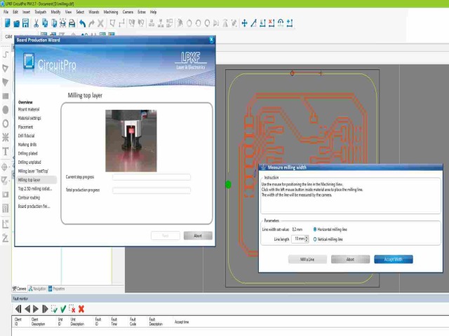
|
|
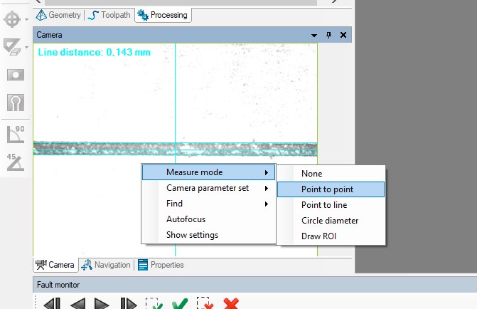
Next, I could check the width of the line from the camera screen. I right-clicked on the screen and select Measure Mode to be Point to point. Picture below left. The measured the width 0.22 mm, which was good result. I pressed Accept width. Picture below right.
|
|
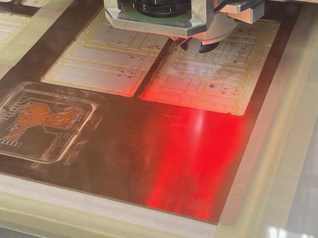
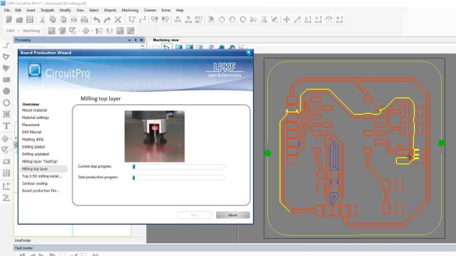
Now the milling started! I was also able to follow the milling on the computer screen. Picture below left. But it is important to keep an eye on the machine, especially when it changed the tool. It may be possible that the machine fails to leave the tool in place and it breaks when changing to a new tool. Picture below right.
|
|
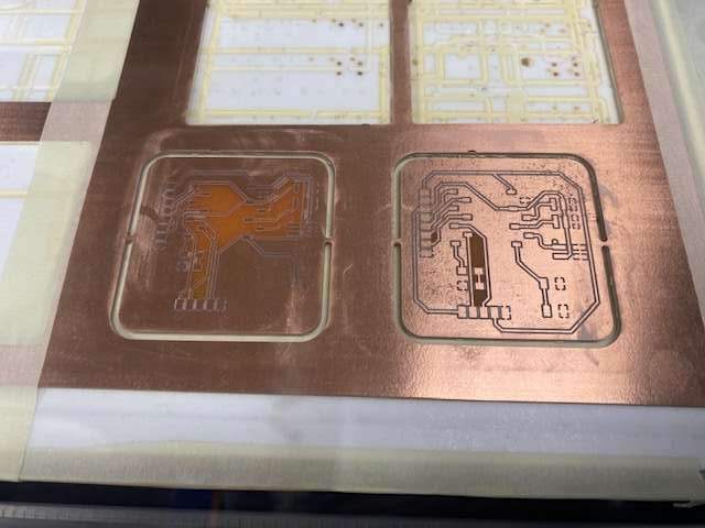
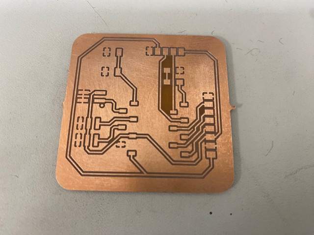
Finished millings in the picture below left. I removed the material and snapped off the board. I cleaned it with steel wool to remove the oxidized copper. Now the board was ready for soldering the components. Picture below right.
|
|
Soldering
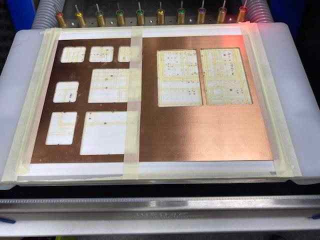
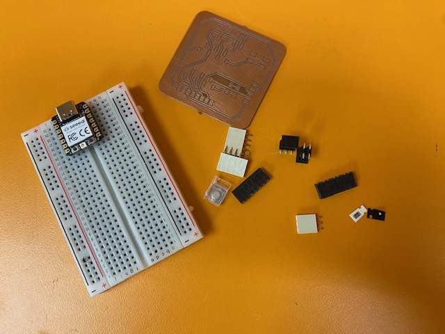
All the parts collected.
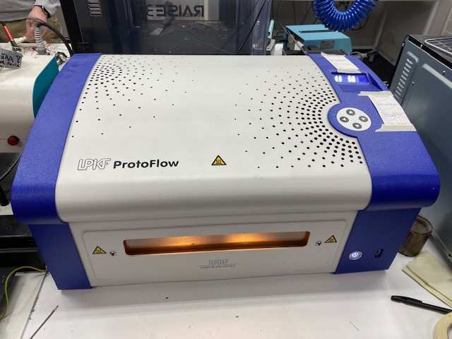
LPKF ProtoFlow oven
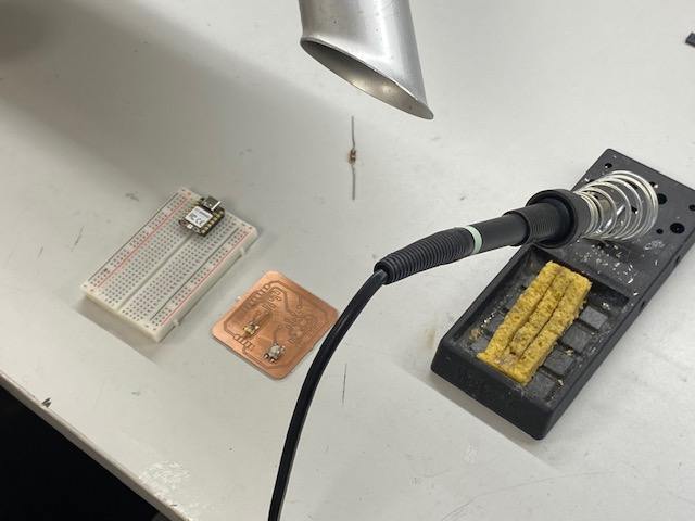
First, we were instructed on how to use reflow oven to solder small components. We used a low temperature solder paste. In the picture below left, I have put a small amount of the paste on the button pad. In the picture below right, I have placed the resistor, LED and push button. We used a reflow oven to solder these three components.
|
|
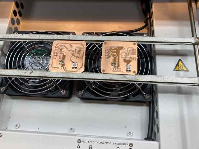
The LPKF ProtoFlow oven we used is in the picture below left. Our instructor set the oven to the low temperature program. Before the machine preheats itself, it is a good idea to adjust the rack to fit the boards. After the oven was preheated, I put the board on the rack. Picture below right.
|
|
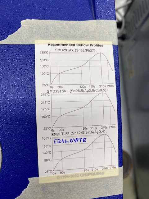
In the picture below is the low temperature profile for the FR1 board material. The heating did not take long and soon the oven made some noises that the process was finished. I took the board out and the result looked fine, so I continued with hand soldering.
Hand soldering
The starting point for hand soldering in the picture below left. I don't know where my components are, but hopefully they are just cropped out of the picture. Before I started soldering, I switched on the main power and then turned on the fume extractor and also the soldering station. I used a temperature of 350 degrees Celsius.
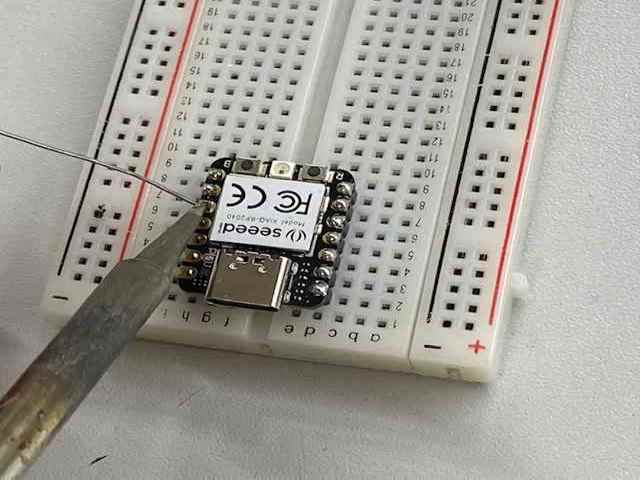
I started soldering with the RP2040 microcontroller. I attached the RP2040 with the pins to a breadboard to keep the pins straight when I soldered them to the microcontroller. First I heated the pin area or pad with a soldering iron and soon added solder. Then I carefully took off the soldering iron.
|
|
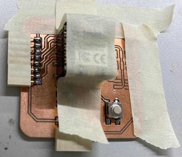
Next, I soldered some connective pin headers to the board. I put the same board material under the component to keep the component straight. Then I taped it so it wouldn't move while I soldered. Picture below left. I also taped the board to the table to hold it in place. When I soldered the pin headers for the microcontroller, I also taped the whole thing to the board. So there was tape everywhere, but it helped with the soldering. Picture below right. If soldering failed, I used a desoldering braid to remove the solder.
|
|
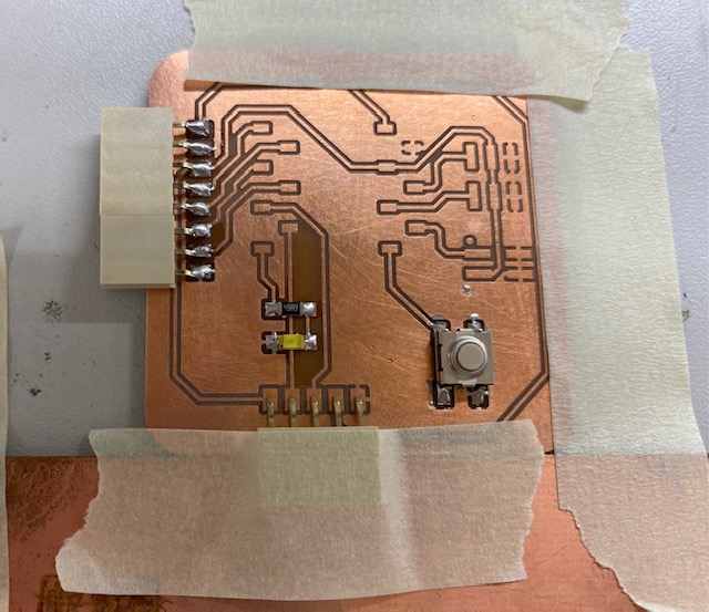
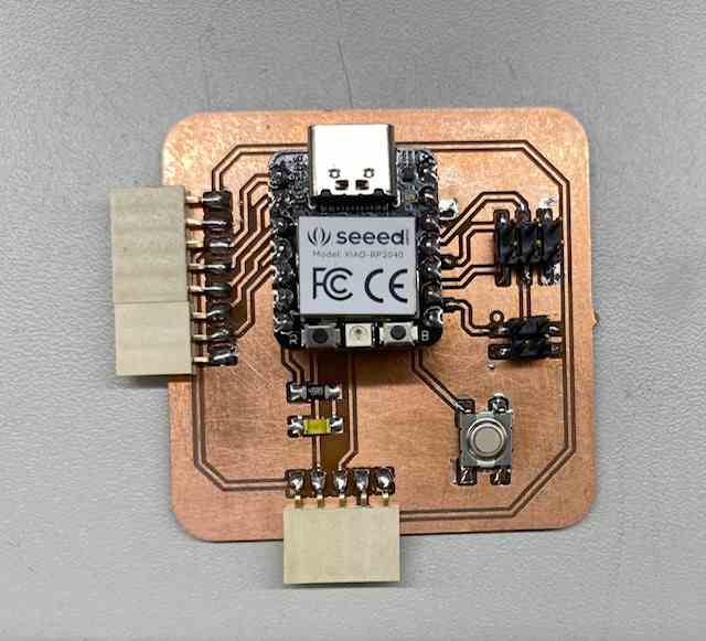
Finished board in the picture below! The soldering went quite well for a beginner. I don't think I have soldered this small components before. In some places the solder went over the pad but luckily they were ground pads, so it didn't matter. In the end, I used a multimeter to test that the board was working, before I started testing it with programming.
Testing
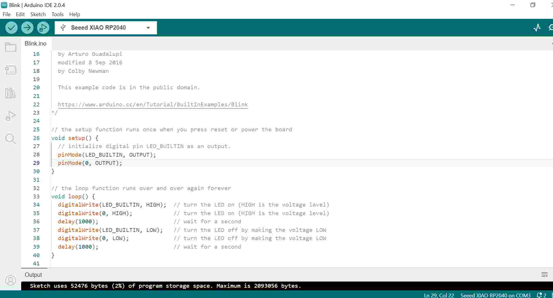
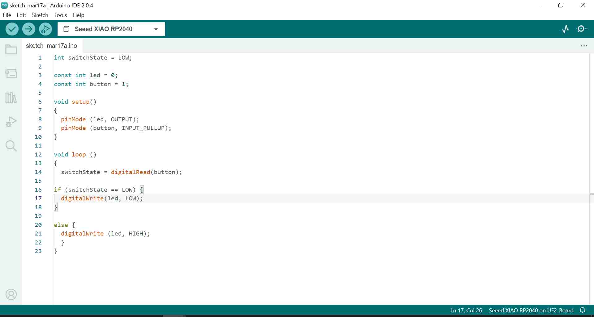
I tested the board with two simple codes. First, I selected the Blink Example from Arduino IDE, but modified it a little by adding the external LED to the code. Picture below left. It worked, the LEDs blinked. Then I wanted to write code where the external LED lights up when I press the push button, and turns off when I don't. I took the model code from the code I tested in week 4 and modified it as I wanted. Picture below right.
|
|
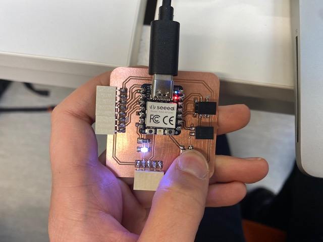
In the picture below, I'm testing code number two, where when the push button is pressed, the LED lights up. It worked. More board tests will follow in later weeks.