4. Embedded programming
Group assignment for this week:
- Compare the performance and development workflows for other architectures
The documentation of group assignment can be found on our group work page.
In this week's local lesson we were introduced to the three boards RP2040, ESP32C3 and SAMD21 from the Seeed studio. In group work we did GPIO test for these boards. The test measures how quickly pins can communicate with a processor core; this is relevant for implementing real-time algorithms that are not supported by processor peripherals. For this assignment we were able to use premade ring oscillator code samples. Functionality for the provited code was writing value to one pin and read from another. The pins are connected and value inverted in a loop. The test results for the different boards were:
- RP2040 with the 9,47 MHz output frequency
- ESP32C3 with the 3,808 MHz output frequency
- SAMD21 with the 1,54 MHz output frequency
Doing this kind of test was completely new to me, so it was interesting to get to know the topic.
Individual assignment for this week:
- Browse through the datasheet for your microcontroller
- Program a microcontroller development board to interact and communicate
Datasheet
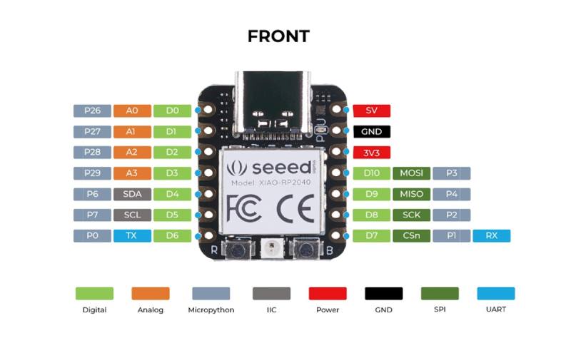
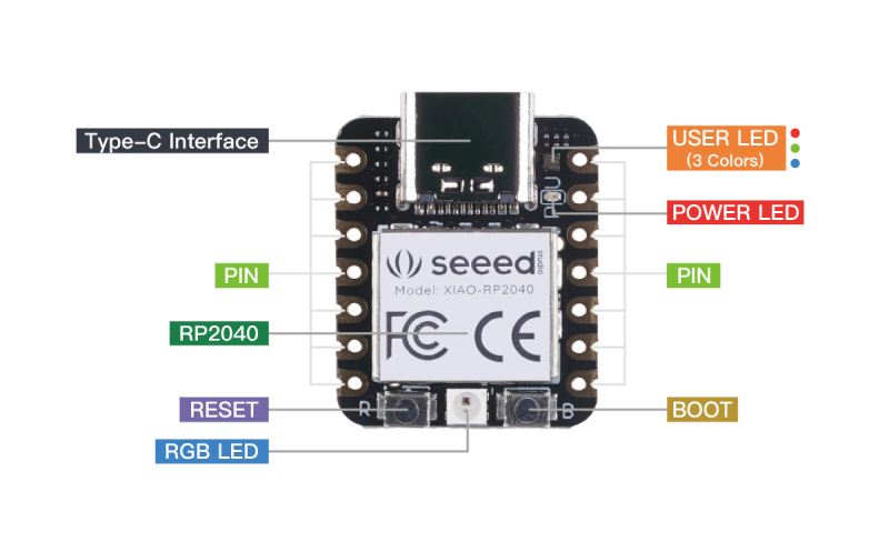
I took a look at the XIAO RP2040 datasheet. Wow, being a beginner on the subject, there's a lot on 646 pages that I would need a giant amount of study on to understand all or even some of it. The most understandable section of the datasheet was in the first few pages of chapter 1, but I felt that more understandable and practical information for this moment I could find on the Seeed Studio website. The most illustrative and helpful images for me from the Seeed Studio website are below:
|
|
There are 14 GPIO PINs on Seeed Studio XIAO RP2040, on which there are 11 digital pins, 4 analog pins, 11 PWM Pins,1 I2C interface, 1 UART interface, 1 SPI interface, 1 SWD Bonding pad interface. In the picture above, the pinout on the left makes it clear to me for which purposes I can use which pin, but if I wanted to know more about them, more information can be found in chapter 5.2. of the datasheet.
I think the Seeed Studio website summarizes well useful information: "On one hand, The Seeed Studio XIAO RP2040 carries the powerful Dual-core RP2040 processor that can flexible clock running up to 133 MHz which is a low-power microcontrollers. On the Seeed Studio XIAO RP2040 there is also 264KB of SRAM, and 2MB of on-board Flash memory which can provide more program to save and run. On the other hand, this little board has good performance in processing but needs less power."
Setting up the board
First step was to download and install latest version of Arduino IDE.
First platform we tested to connect to the computer was RP2040. After we were tested RP2040 we tested to connect the ESP32C3. The steps to connect different platforms were quite similar:
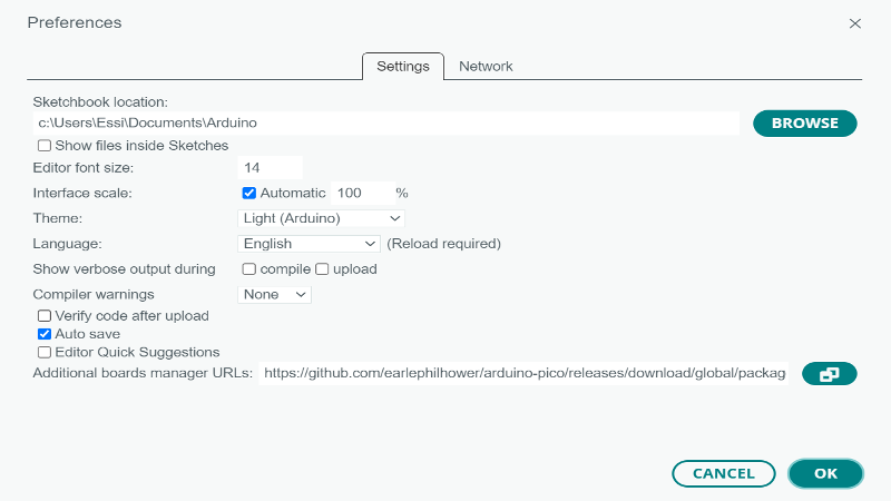
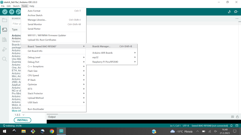
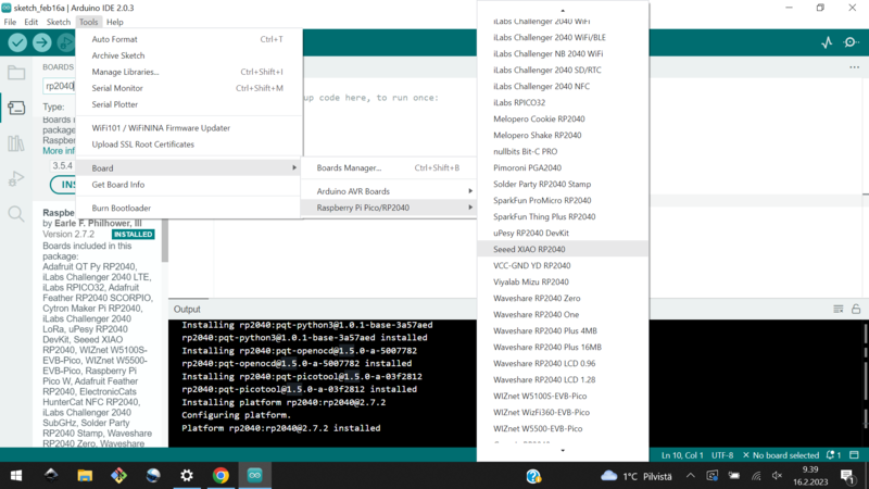
1. Add the board package of platform you are using to your Arduino IDE. We were given the URLs for platforms which I placed to Additional Boards Manager URLs -section, found in Preferences under the File menu. The URLs for these Seeed Studio XIAO platforms can be found on their website. Then navigate to the Tools -> Board -> Boards Manager and search the board, in this case RP2040 (Rasperry Pi Pico/RP2040 by Earle F. Philhower, III Version 2.7.2) and install it.
|
|
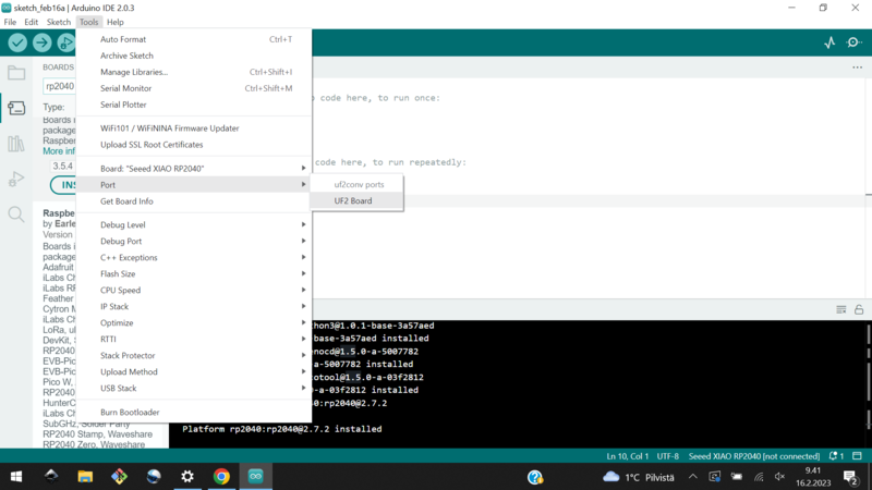
2. Select the right board from Tools -> Board and select the right port from Tools -> Port.
|
|
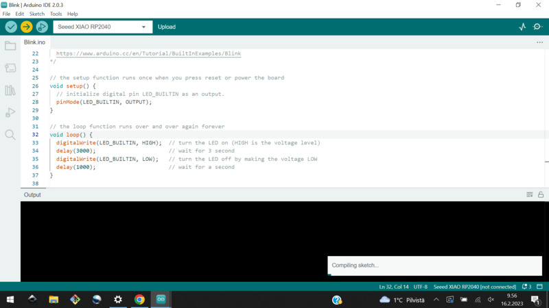
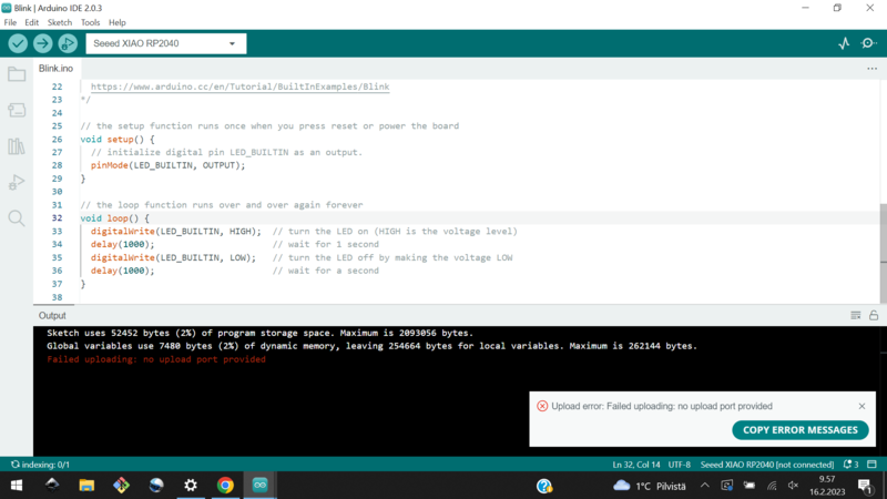
3. Test the connection with the built-in example code "Blink" from the File -> Examples -> 01.Basics -> Blink. The sketch will open in a new window and you can upload code to the board by clicking Upload button in the top left corner. Picture below left. When I first tried to upload the code, an error message appeared on the screen and I noticed the port wasn't selected when the sketch were opened in new window. Picture below right.
I select the right port and tried again. The connection was now working and I could see the user LED blinking on the board (this when using Seeed Studio XIAO RP2040, for ESP32C3 should have an external LED to see any blinking).
|
|
Programming
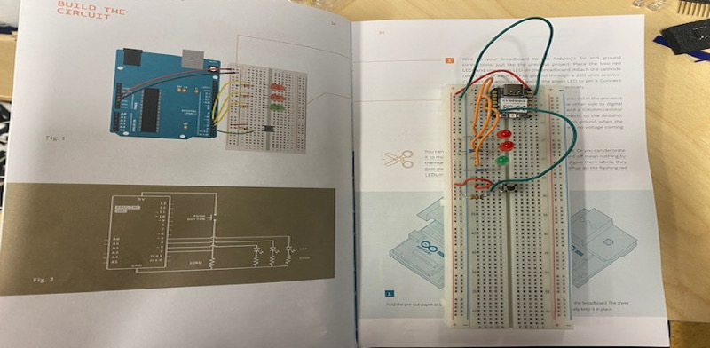
At first, I found programming assignment a bit difficult and wondered what I could do. For me, the most concrete idea seemed to be to program the LEDs to work with a switch. When I was wondering where to start, I picked up a Projects Book of Arduino Starter Kit from BusinessAsema Fab Lab.
I decided to choose the "Spaceship Interface" project from the Project Book and borrowed components from the Starter Kit to build the circuit on the breadboard. I don't remember using a breadboard much before, so now I was able (with the help of the Starter Kit book) to get more familiar with it. I read the instructions for building the circuit in the book, but checked the picture of the Seeed XIAO RP2040 to see which component I would connect to which pin. The idea of the "Spaceship Interface" project is that the green LED stays on until the button is pressed. When the button is pressed, the two red LEDs start blinking and the green LED turns off. The circuit is in the picture below left.
Note! In building this circuit, I made a mistake in my lack of understanding and connected power to the push button at 5 V. This can cause chip damage, as the Seeed Studio website says: For general I/O pins: Working voltage of MCU is 3.3V. Voltage input connected to general I/O pins may cause chip damage if it' higher than 3.3V.
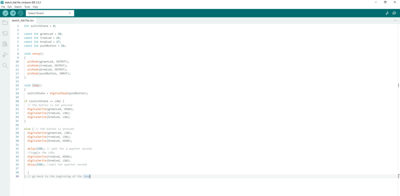
I also wrote the code for programming using the code from the "Spaceship Interface" project, but modified the code to correct my circuit. I added "const int" keywords to the beginning, that specifies that a variable's value is constant. I saw this on the how2electronics page in the tutorial and found that it made it easier to write the code later, as I didn't have to keep checking to make sure the pin number was correct. I named one red led tredLed because it was the top red led and the other bredLed because it was the bottom red led.
|
|
The exciting moment came when the code was ready and I first tested it with the verify button and it seemed to work, then I uploaded it to the board... And the result was that when the button was not pressed, none of the LEDs were on and when the button was pressed, only the top red LED blinked:
The first thing I noticed was a circuit mistake, the bottom red LED was connected incorrectly. I fixed it and now both red LEDs were blinking, but the green LED was still not working. The green LED was connected correctly. Next I tested if the green LED was OK. I replaced it with the red one and the green LED worked, so it was not broken.
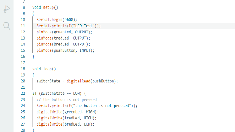
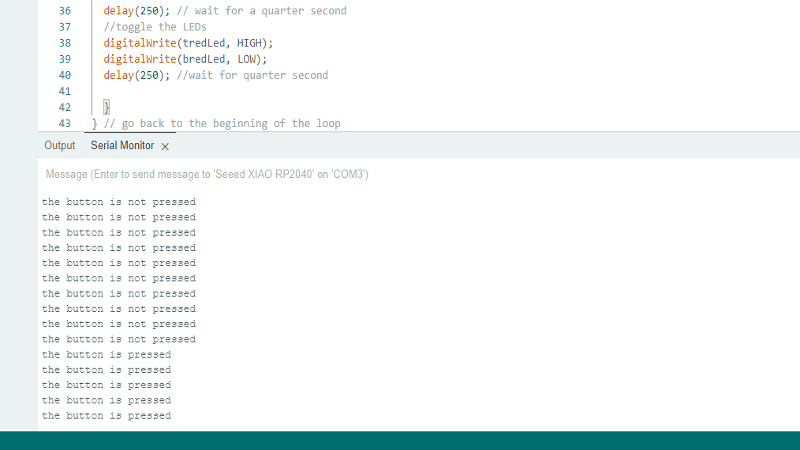
My Fab Academy student friend Tapio also came to check the situation and he advised me to write the code to print data to the serial port and helped me with that. I was not familiar with the serial before, but eventually I understood its purpose used for communication between the Arduino board and a computer or other devices. Through the serial monitor I could see that the loop was working correctly and the connection was working:
|
|
The last thing I tested was to change the pin of the green LED, and after changing the pin from 28 to 6, the code worked. So pin 28 may have had a contact problem or some other problem. Finally, the green LED stayed on until the button was pressed, and when I pressed the button, the red LEDs were blinking:
Yippee, I was happy!