Electronics design
Group Assignment
2023
Here is link to our group assignment
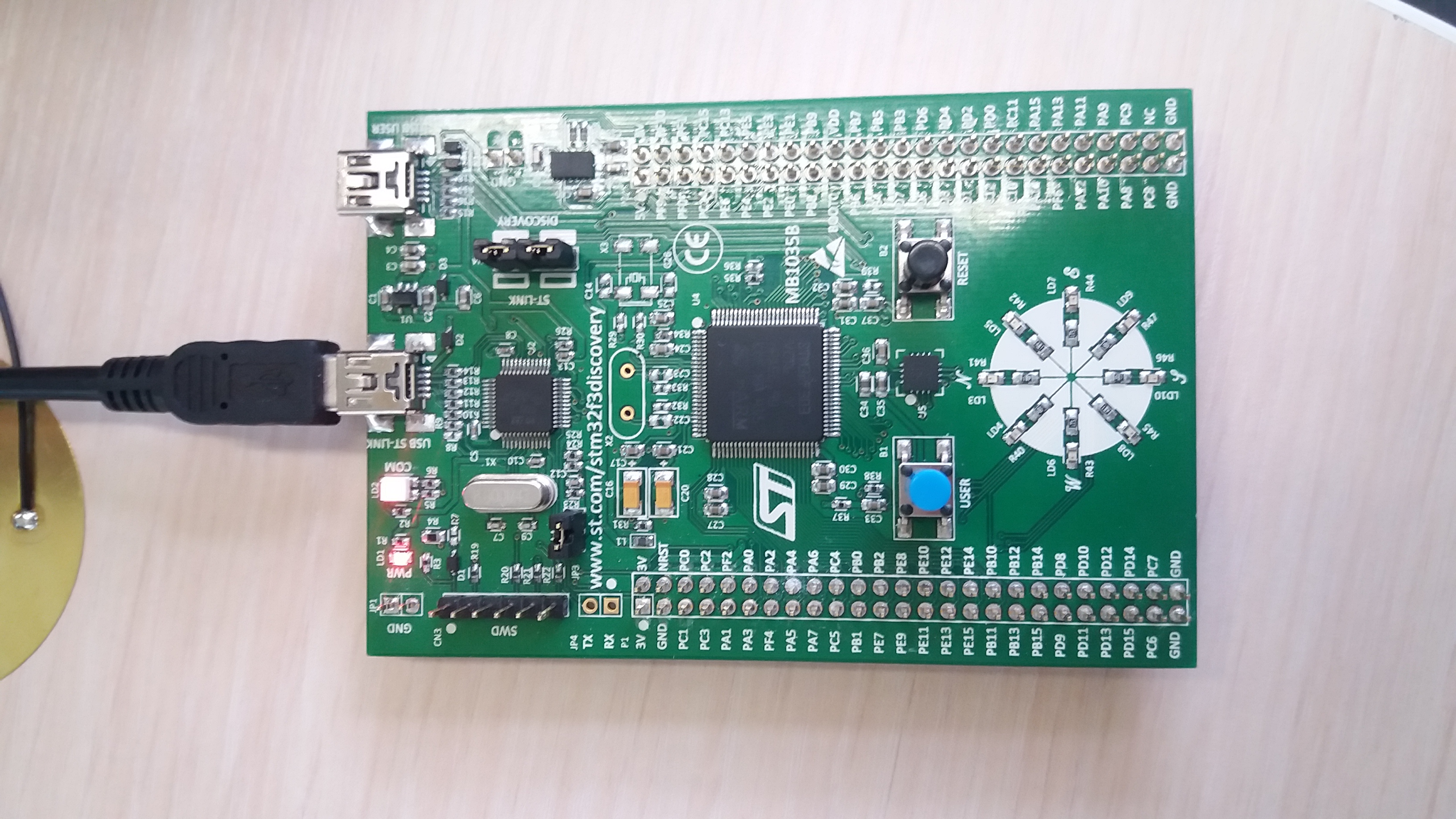
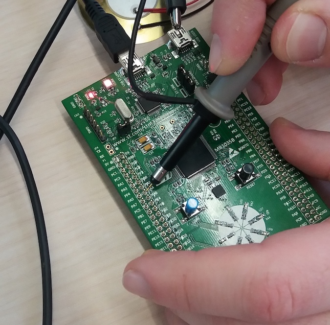
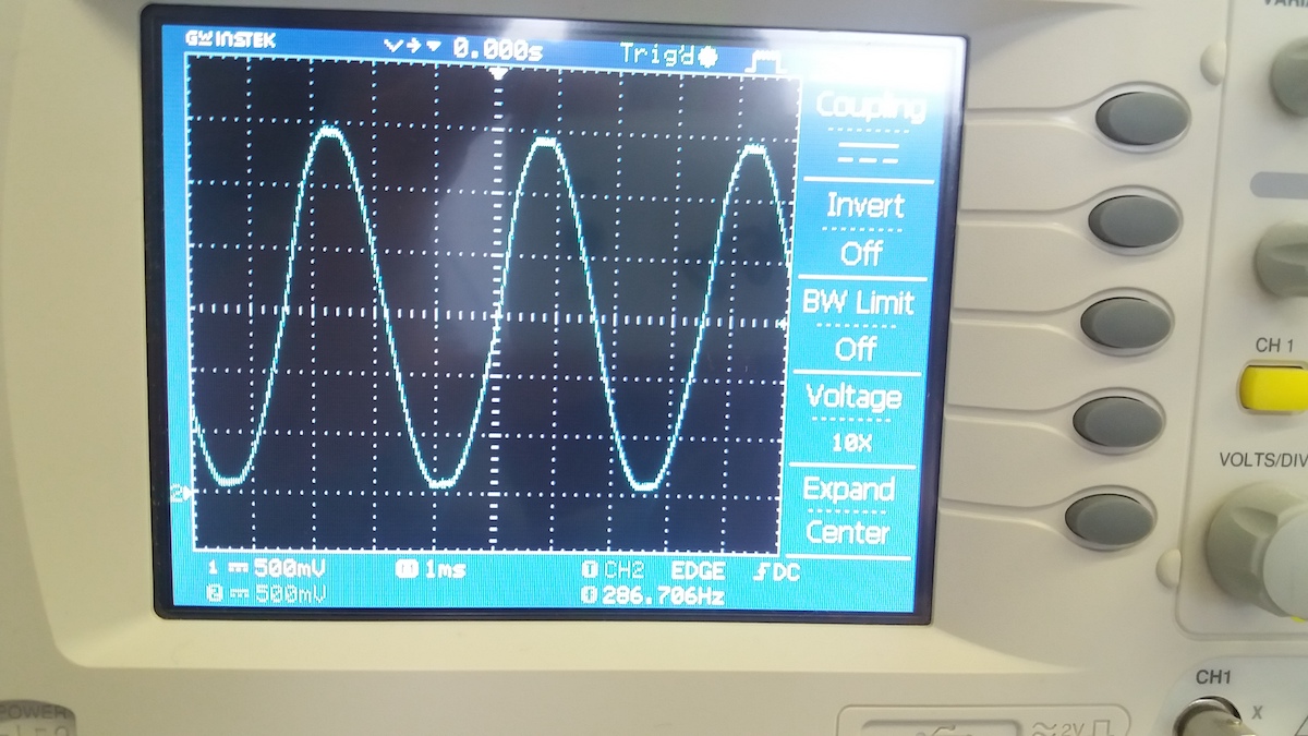
We generated code for STM32 board with chatGPT to generate ramp and sinusoidal signals, and observed it with osciloscope
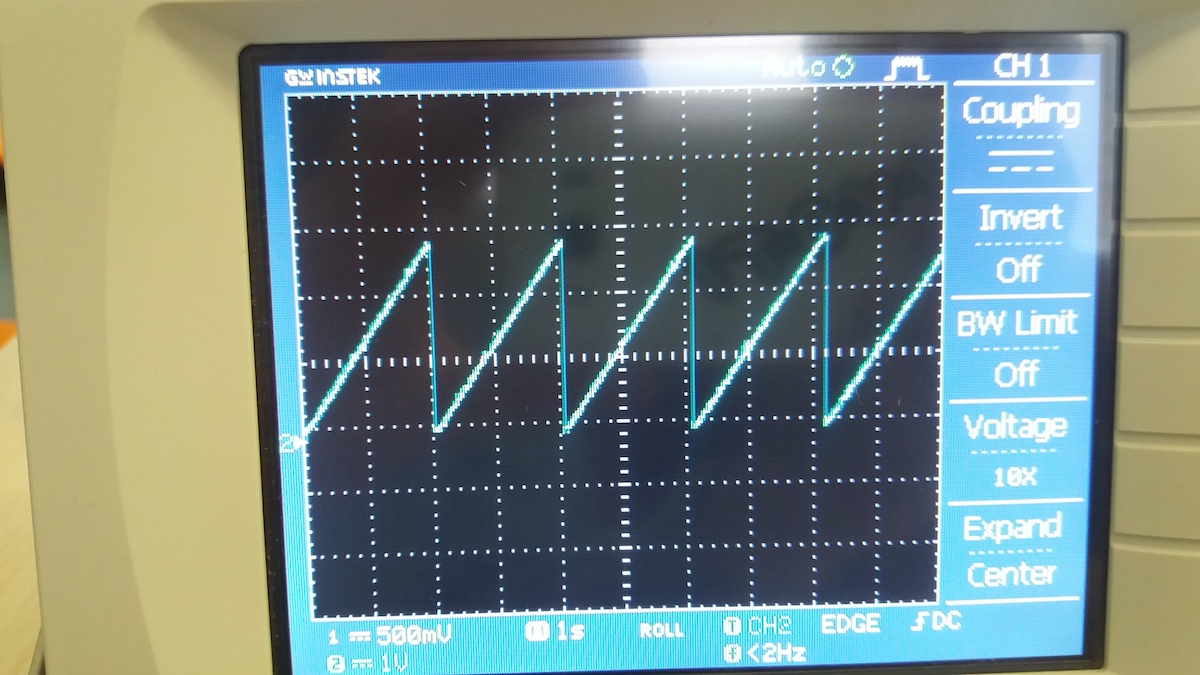
Here we can see Ramp signal
And here - Sinusoidal Signal
Research
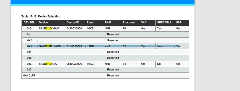
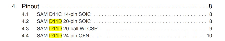
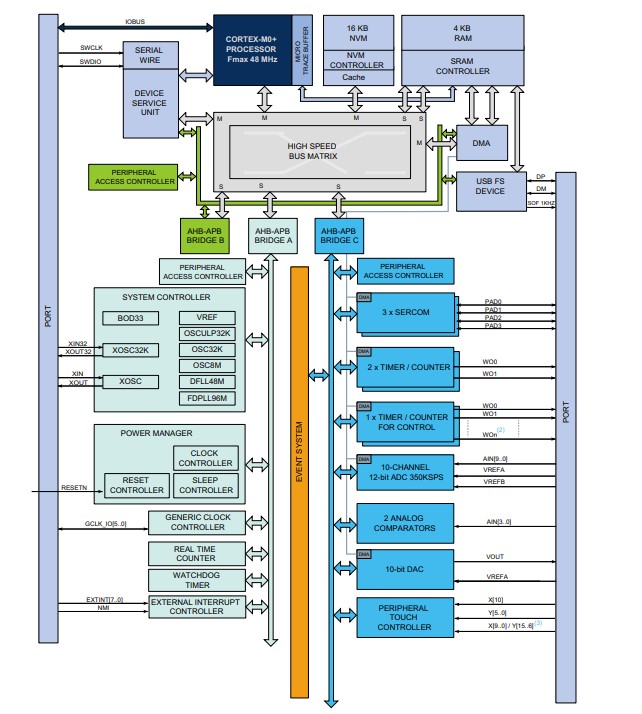
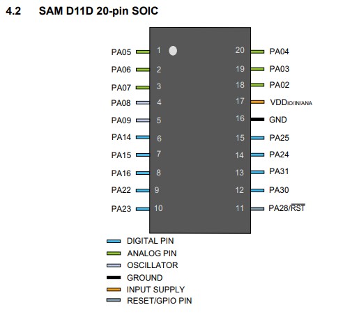
I’m going to use SAMD11D14SS, I’ll check it’s documentation to find information i need.
Adding FAB library to KiCad
Here is link
I did all steps, that written in README.md file

After finding library in google i go to git.
 []
[]
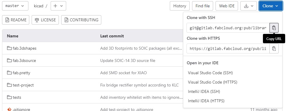
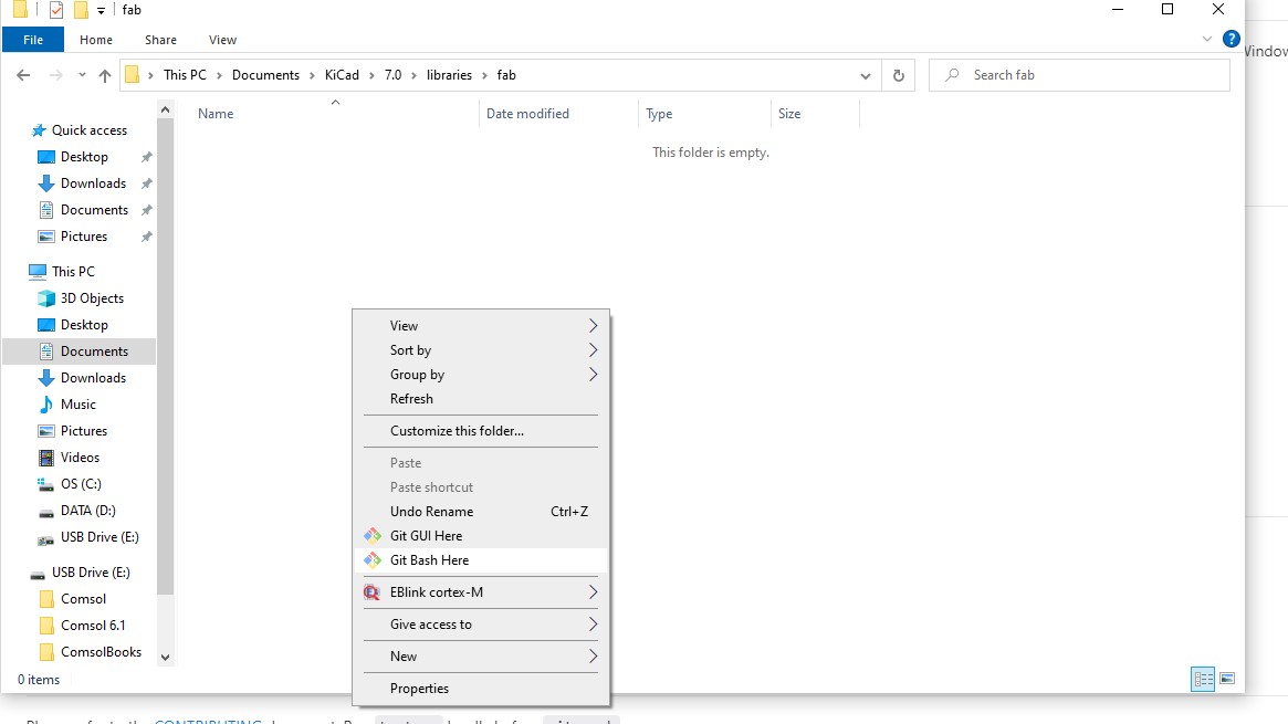
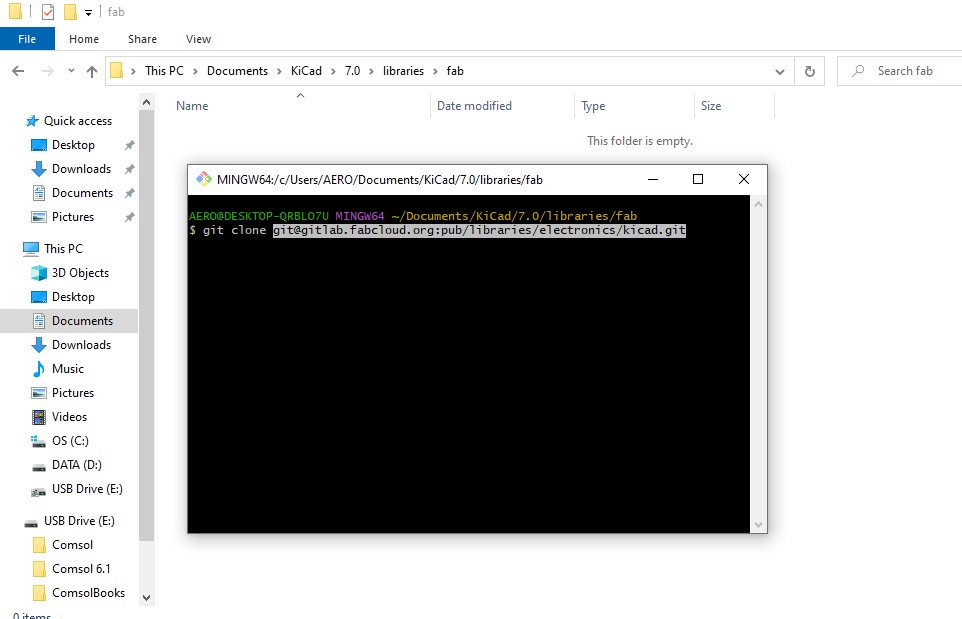
And clone everything in some folder on my pc.
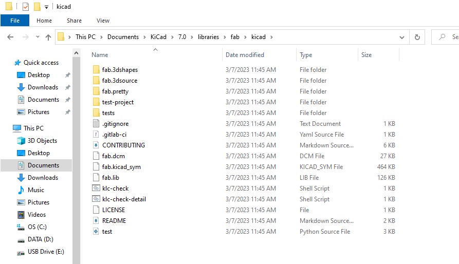
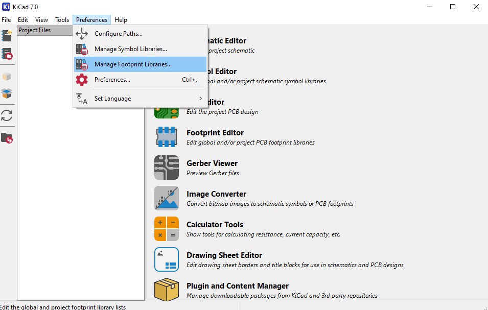
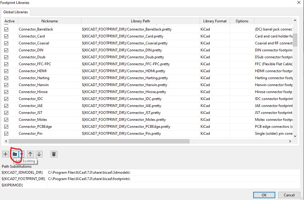
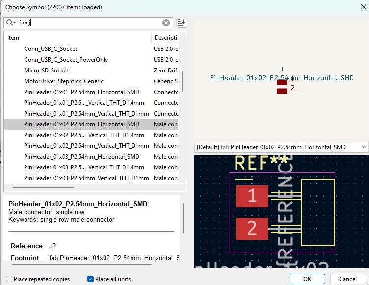
Then I go to KiCad and add “fab.pretty” folder as footprint library
and “fab.kicad_sym” fila as symbol library
Design
2023
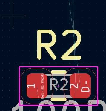
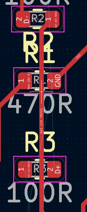
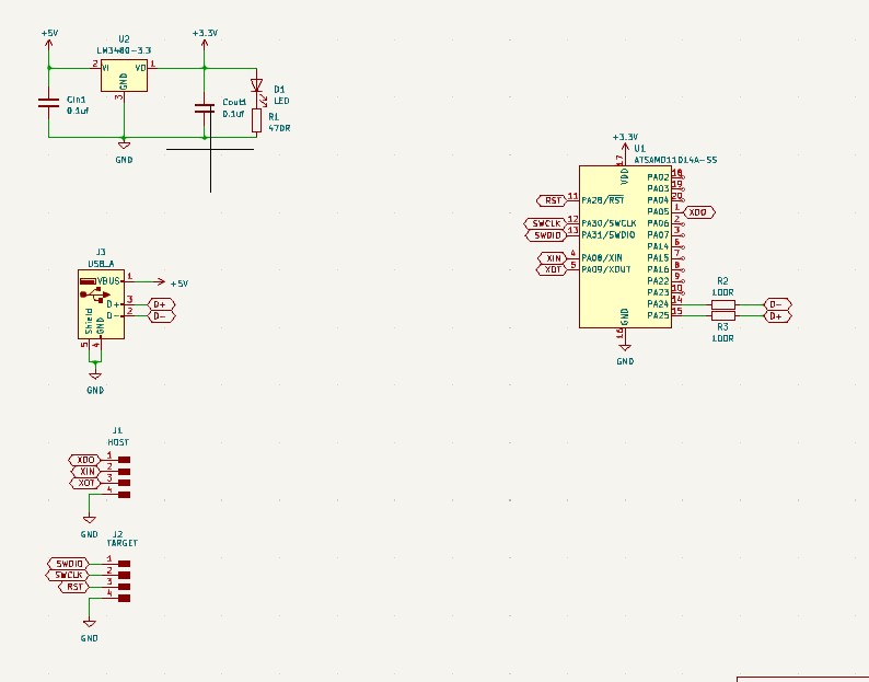
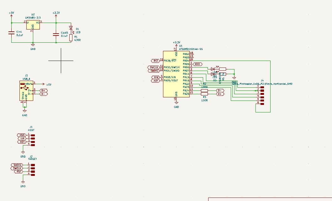
I have to put pull-up resistors on D+ and D- pins.


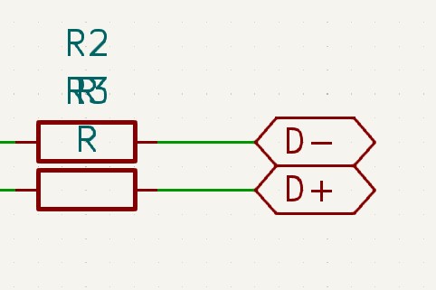
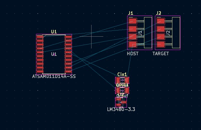
After making some connections in schematics i tried to connect them on PCB
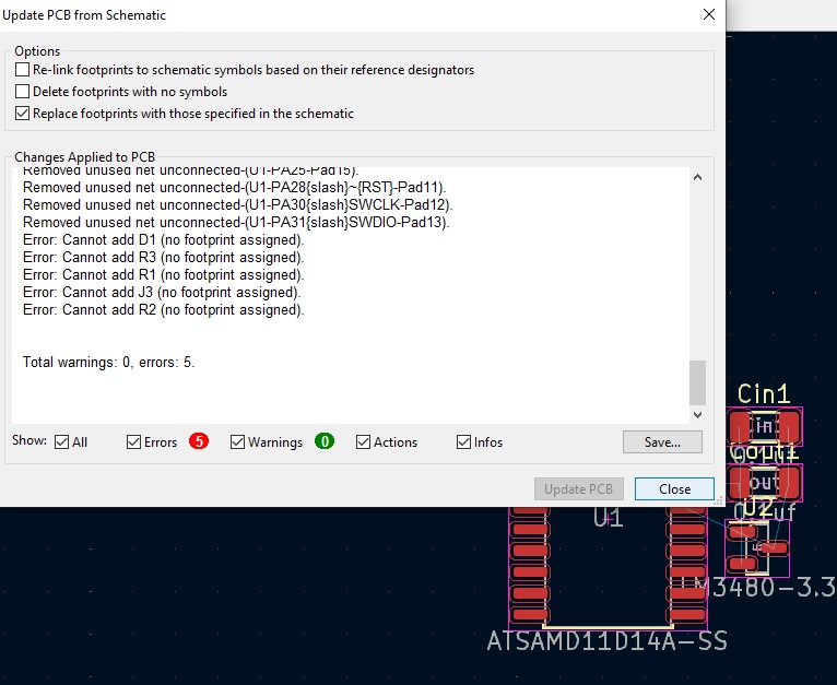
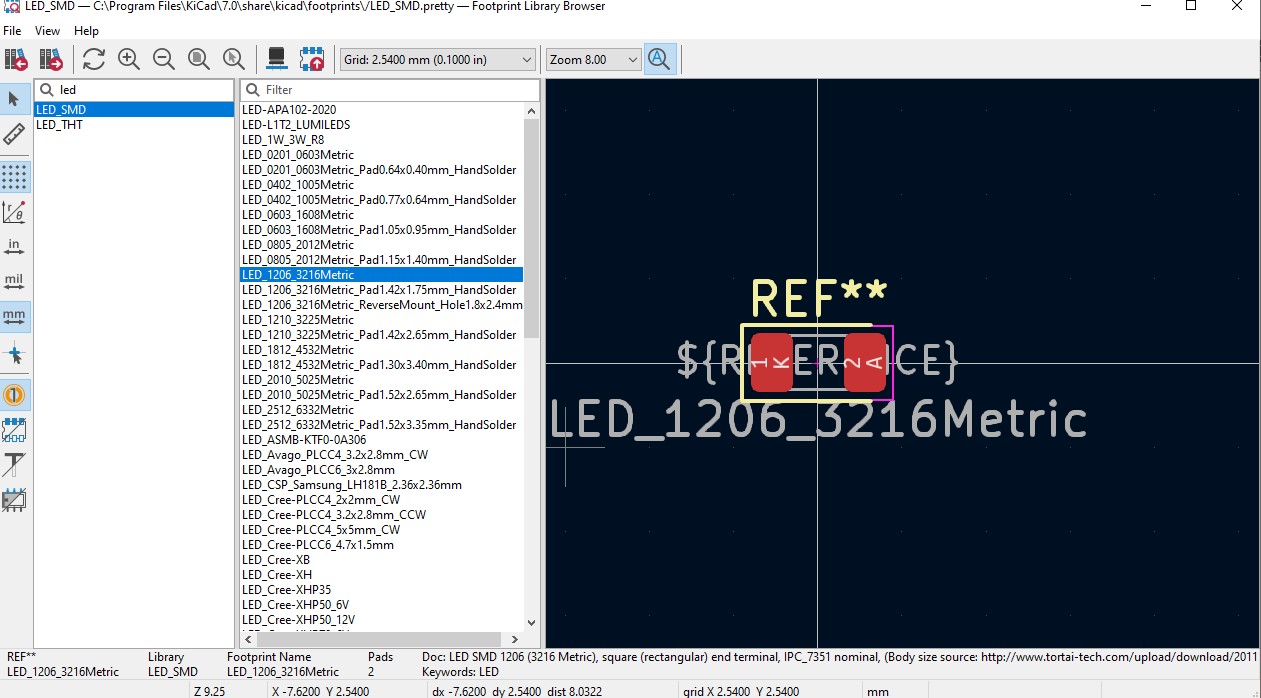
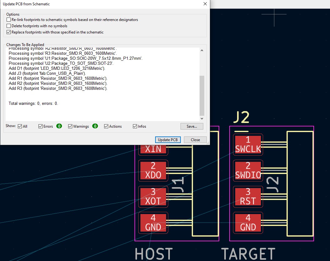
There was error showing that symbol didn’t had footprint. So in that case i am choosing footprint manually.
Here i am changing Global Label places, not to use 0R resistors.
Also you can rotate elements and draw tracks between component pins.

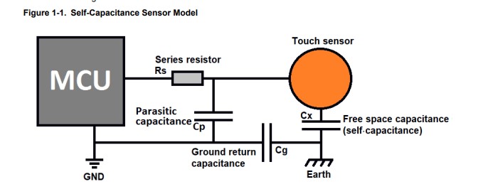
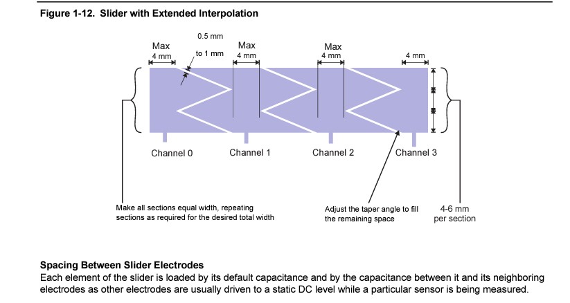
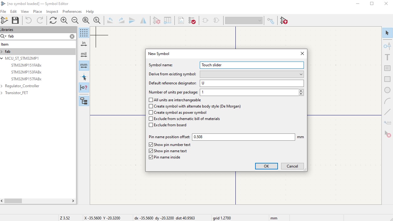
I want to add Touch sensors in my pcb, so i made reasarch about it.
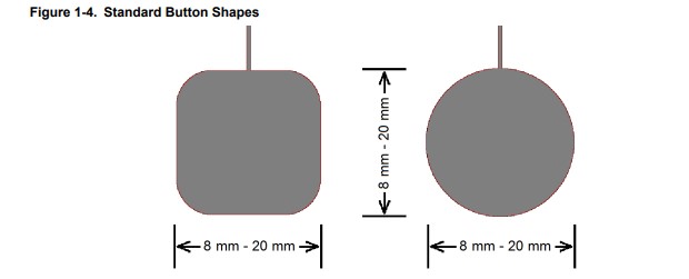
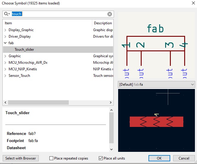
Then I found Touch slide footprint and decided to add it
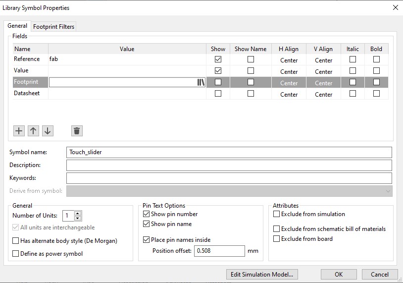
I couldnt find symbol for slide, so i made it by myself.
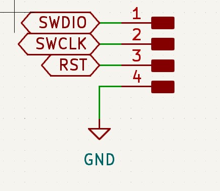
Here is some information how to connect slide to microcontroller
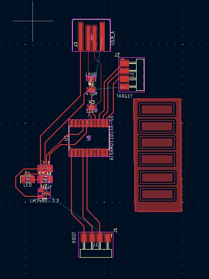
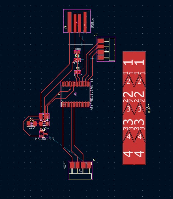
After adding slide in schematics i go to PCB design
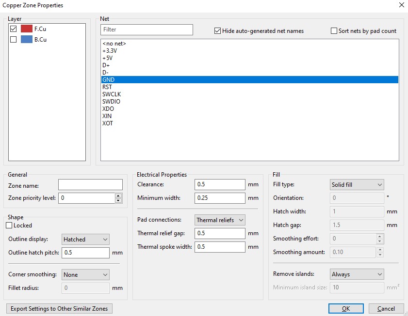
I set all zone as GND , to connec all “grounds” to board, not to have more tracks.
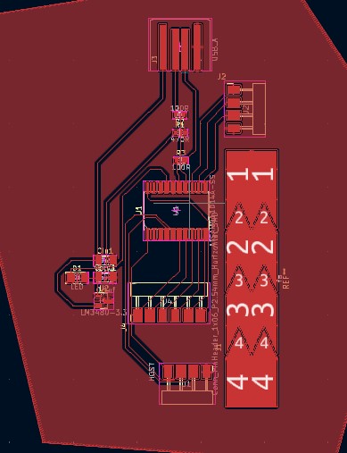
Then I draw my outline, and its all.
BUt i couldn’t conect tracs to slide, because it doeasnt have footprint.
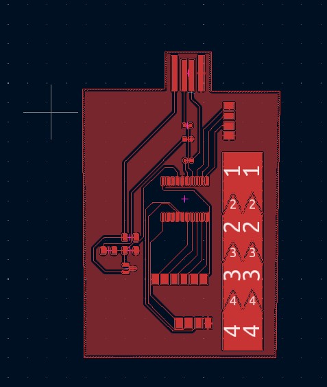
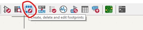
So i made footprint by myself in footprint editor.
Also i added connection pads to slider.


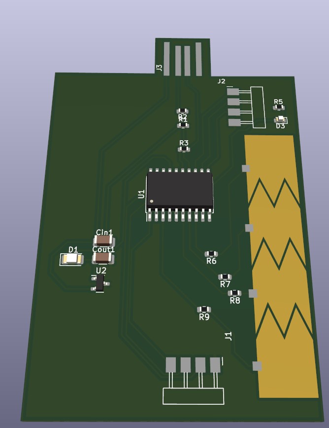
And here is it, 3D view of first PCB i’ve ever made.
Atiny44a development board
Then i decided to design Attiny44a development board, and try to program it with Arduino UNO as ISP
My instructor Onik told me that function, and i want to try it, and i found much information about it here
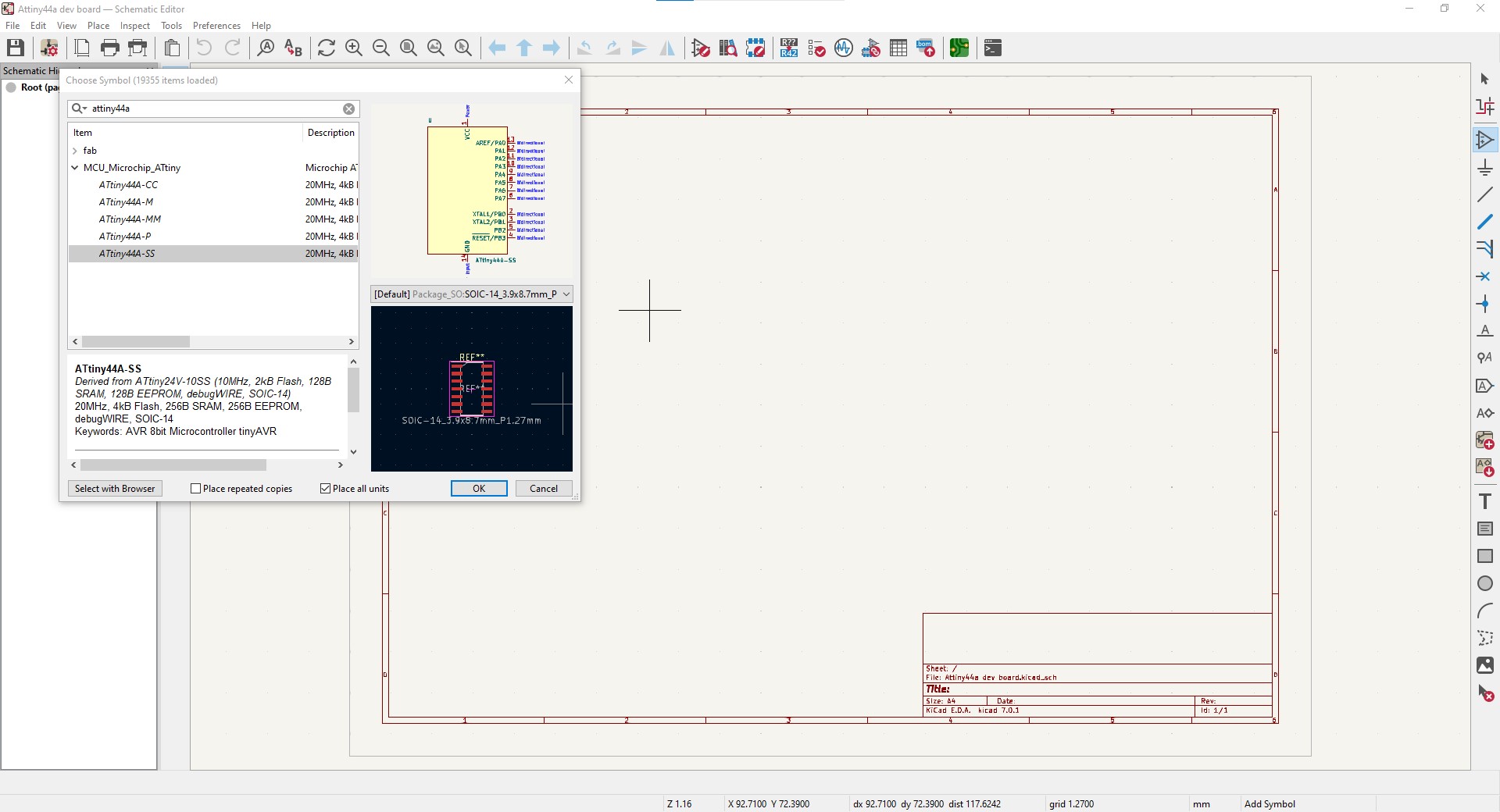
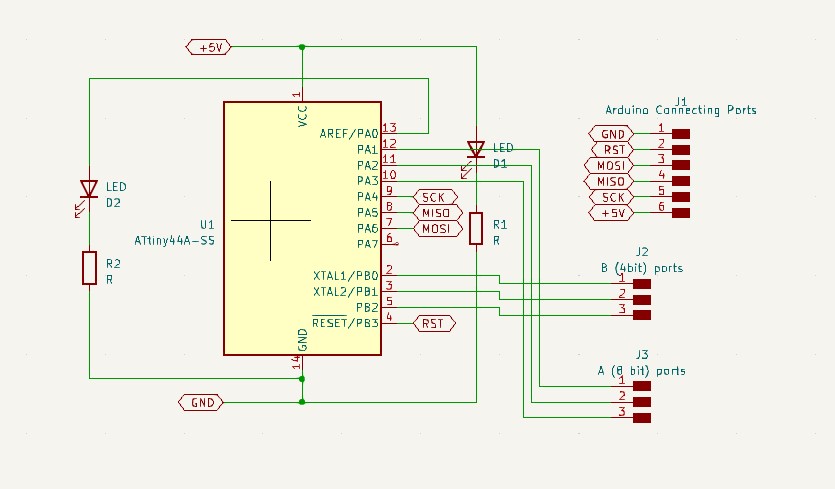
For first, i added Attiny44a to my schematics
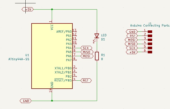
And then Added pins to power it, also LED to see, if it is powered and
PINs to connect to Arduino UNO.
Then i added 6 more pins, to use them as input or output pins.
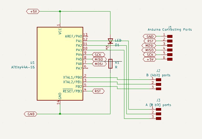
Also i added one more LED, that is connected to one of pins, to control it.
After some research, i found that LED’s that i want to use operates at 2-3V DC and 20mA current,
As Attiny44a pin gives 5v at “HIGH” position, i must connect resistor to my LED.
To calculate resistance I will use Ohm’s Formula I=U/R.
R max = (5V-2V “min value of voltage on LED”)/20mA=150 ohm. R min = (5V-3V “max value of voltage on LED”)/20mA=100 ohm.
So i need Resistor from 100 to 150 ohm resistors, to connect in a series to LED.
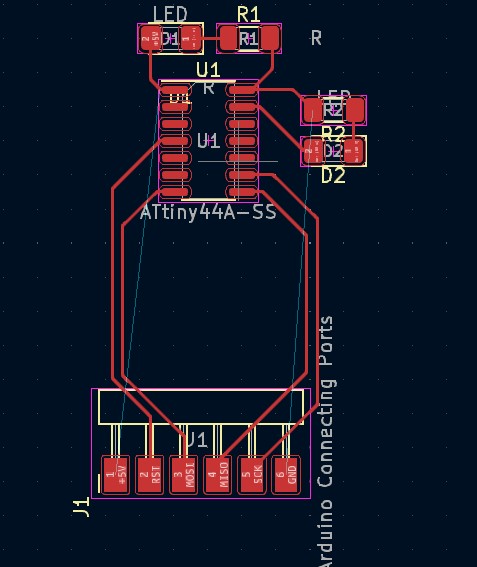
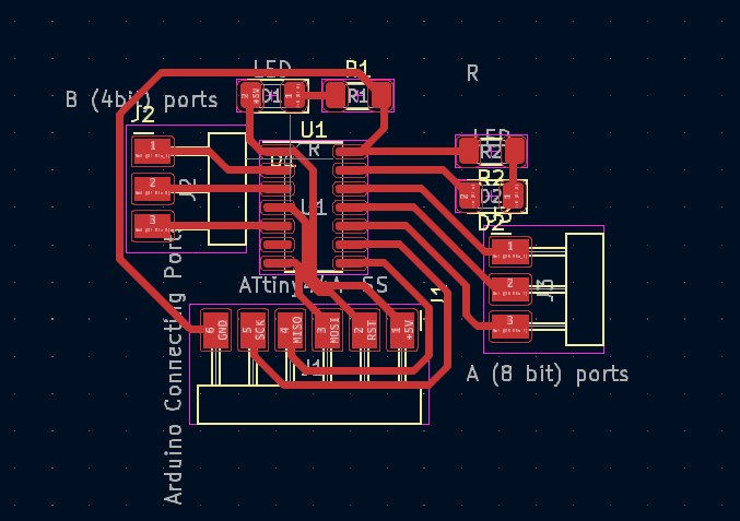
Then, in PCB design, i added my elements
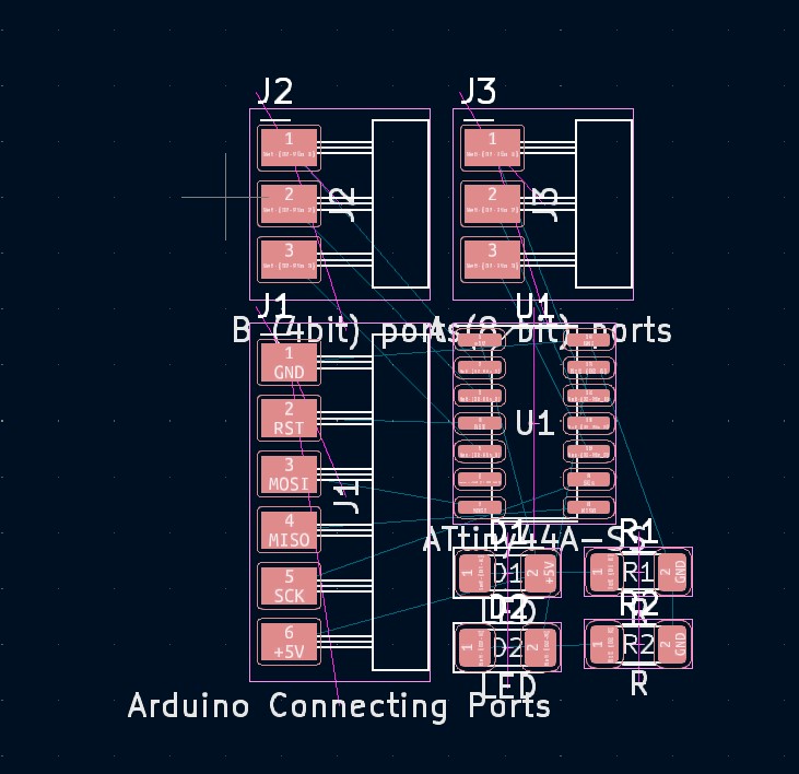
and started to connect them.
Here i had problem of crossing lines
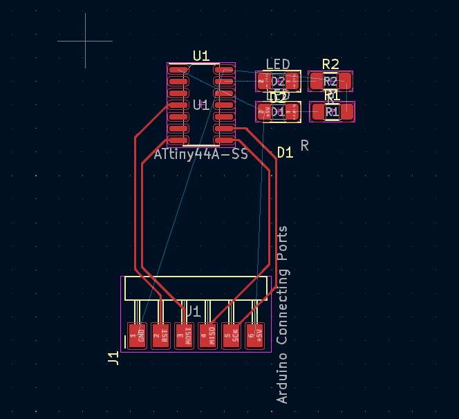
So I went to schematics, and changed positions of pins.
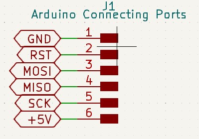
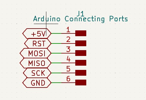
Problem solved:)
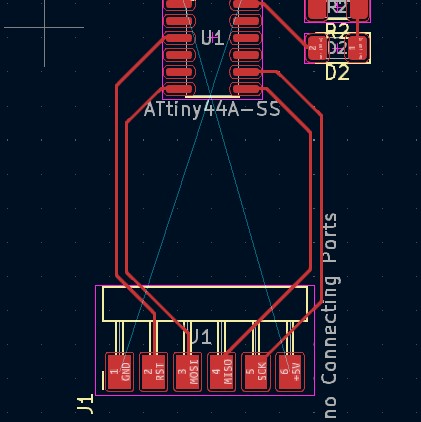
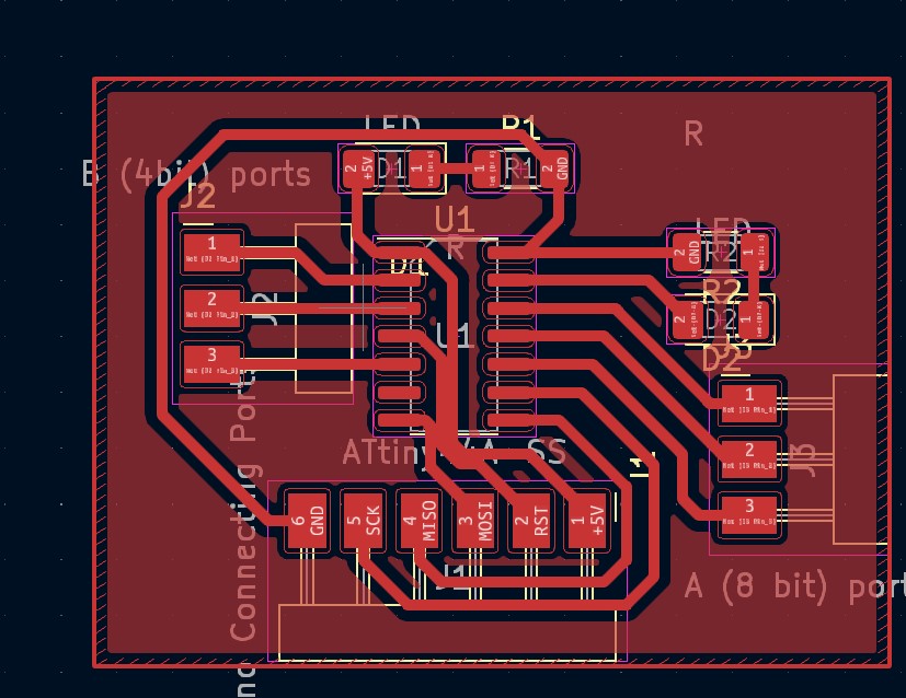
here gap between tracks is too small, so i moved elements a little bit and here it is
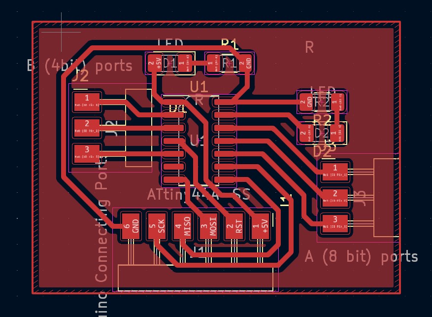
Lets draw outline.
Here is my PCB design
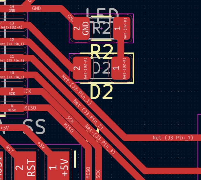
Noticed, that there is 2 tracks connecting in left lower angle of attiny (middle element of PCB) and solved it
2025
Amplifier Circuit
I am using output from transductor in my final project, which gives output in range of 0-50 mV. To work with that signal (To use DSP tools) I need to amplify it.
I designed circuit which amplifies my signal 50 times and makes it in range of 0-2.5 V.
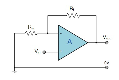
After some research i came to OpAmp non inverting amplifier circuit
Before designing it , i want to simulate it’s work, and i am using NI Multisim which is unfortunatelly not open-source, but there is free alternatives as LT Spice
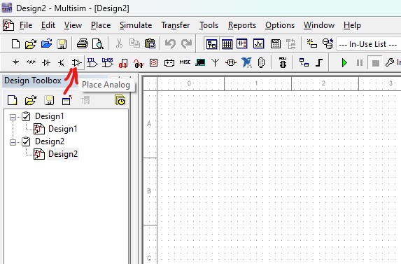
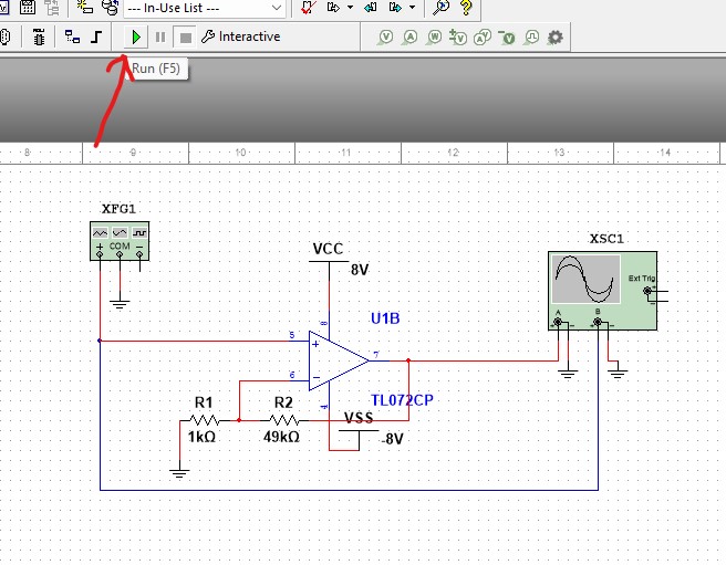
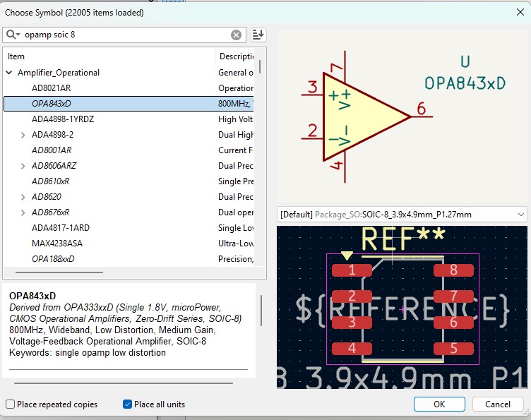
I am starting simulation by creating circuit. For first i found my OpAmp.
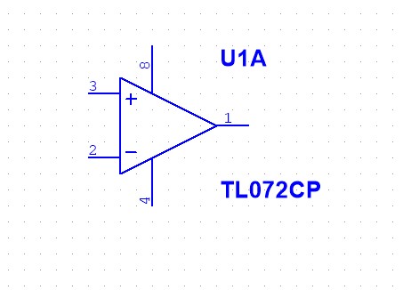
I am using TL072, as it is commonly used for that type of applications.
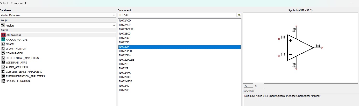
Here it is
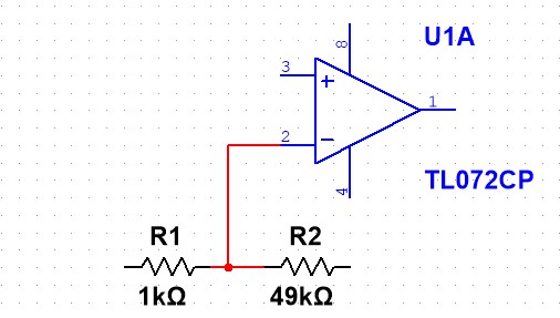
Then i added resistors
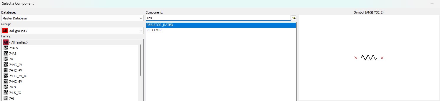
I will use 1 kOhm for R_in and 49 kOhm for R_f. The gain will be 1 + R_f / R_in = 50.
I changed resistance of one resistor to 49 kOhm, by double clicking on it, and changing parameters.
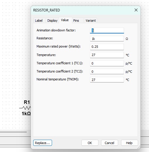
now i have what i need.

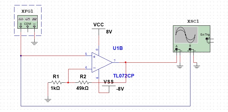
then i connected every element by wires (click and drag for wiring)
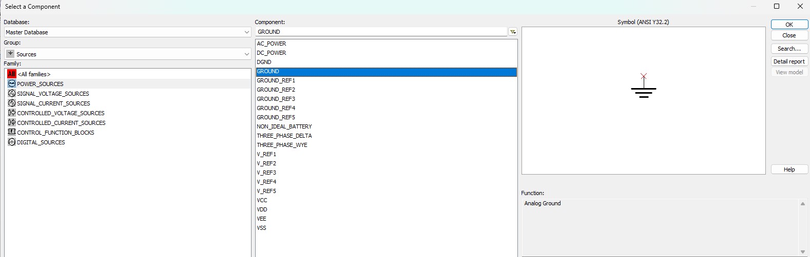
for powering opamp, and grounding circuit i found components in “Sources” group.
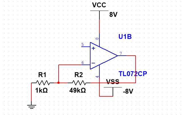
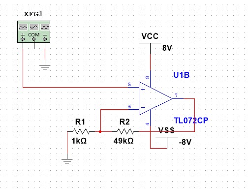
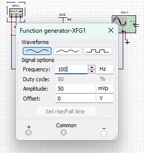
For generating input signal i used “function generator” tool
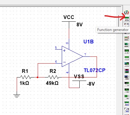
and connected to circuit
For measuring output signal I used oscilloscope tool. I found good tutorial for function generator and oscilloscope tools.
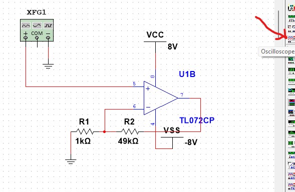
And also connected it. I will insert output signal in channel A, and input signal in channel B
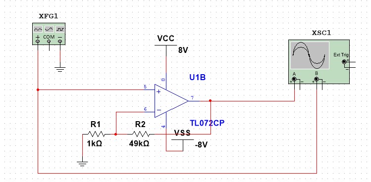
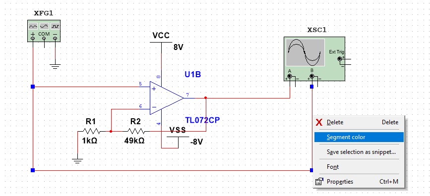
As you can see the wires are same color. In that case, oscilloscope will show input and output signals in same color, which is not that comfortable, that’s why i am changing color of one wire.
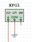
One mistake, i grounded - instead of com in function generator
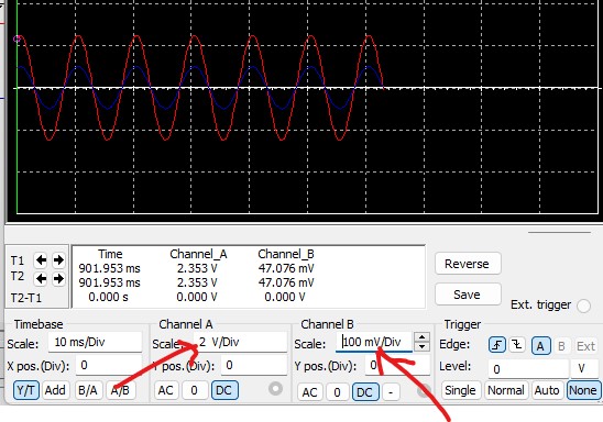
I will generate sin wave with amplitude of 50 mV and 100 Hz frequency as my input signal.
let’s start simulation
You can see that blue signal (input) is straight line, instead of sin wave, that’s because wrong scale configuration in oscilloscope

So after setting them up, everything is perfect.
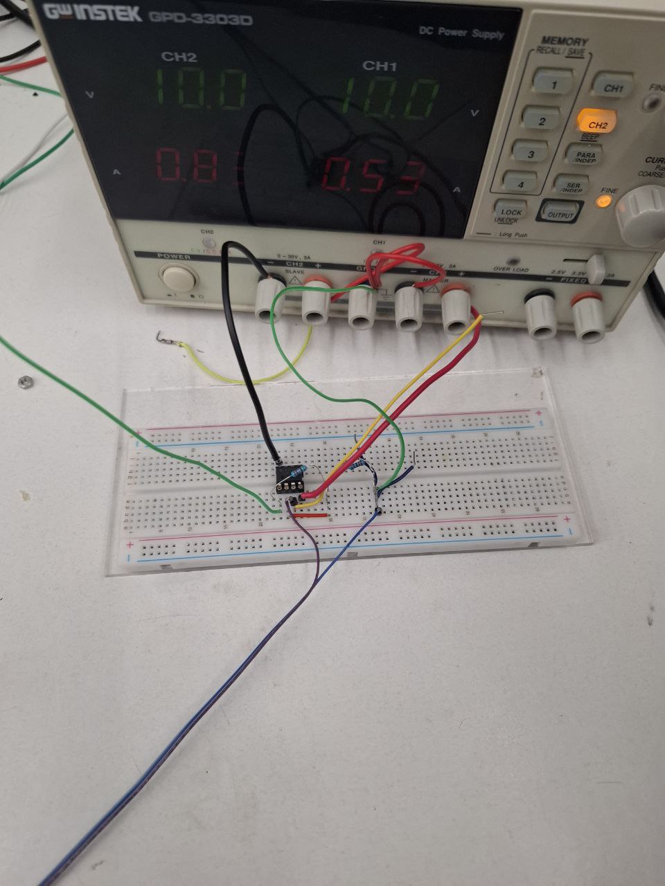
So i started to make my circuit on breadboard to check its work

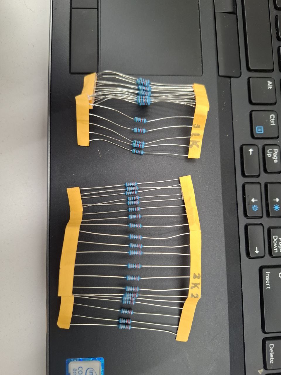
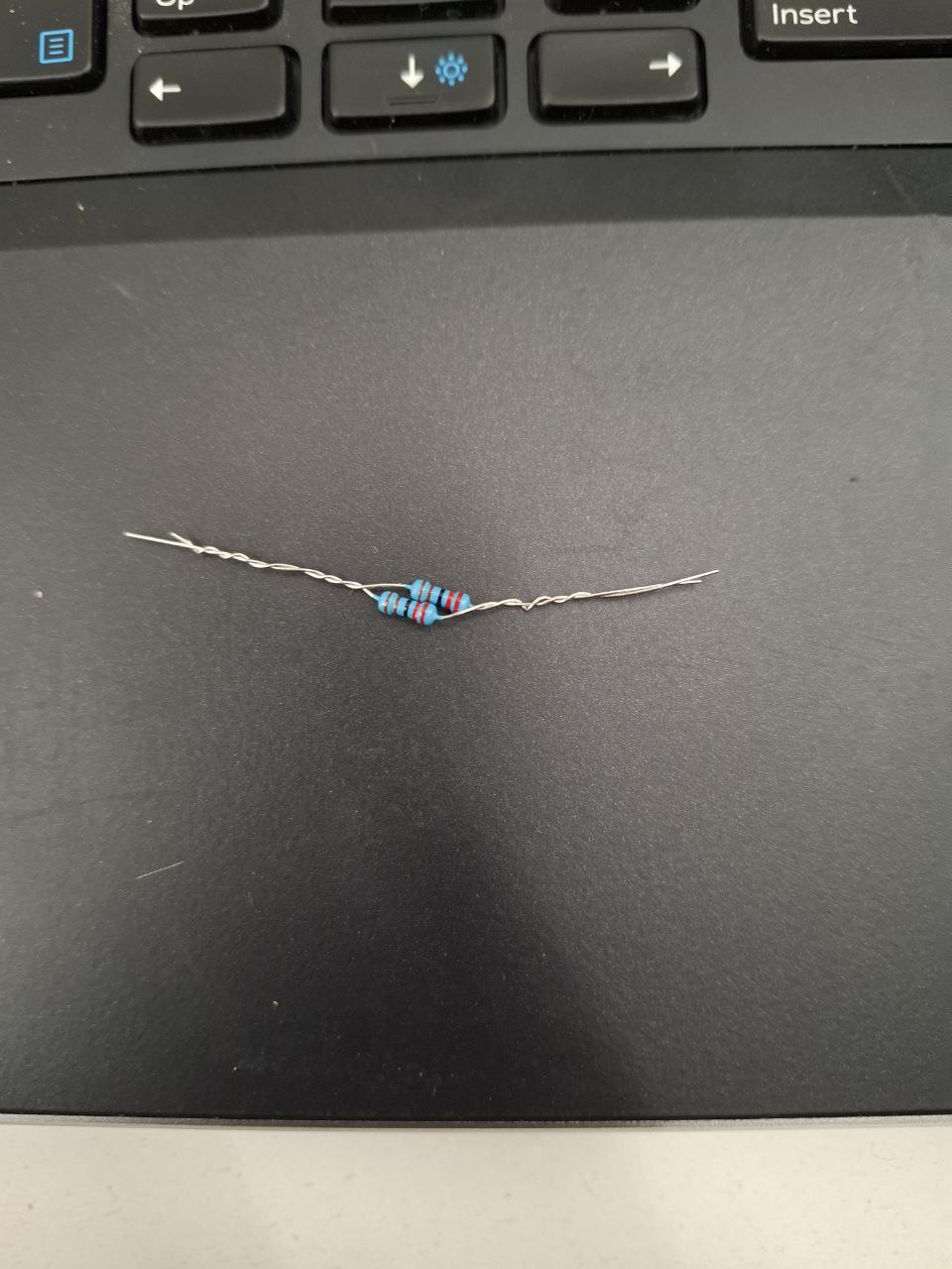
I found 51K and 2K resistors, so i connected 2 2K resistors parallely to have 1K
I connceted Piezo element to my guitar to read its Vibrations
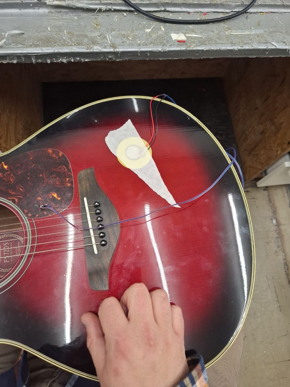
I wired my Power supply, to have +10V, GND and -10V outputs. (By the way i leatned this method from FabLab YouTube channel )
I connected my osciloscope probes to read input and output signals.
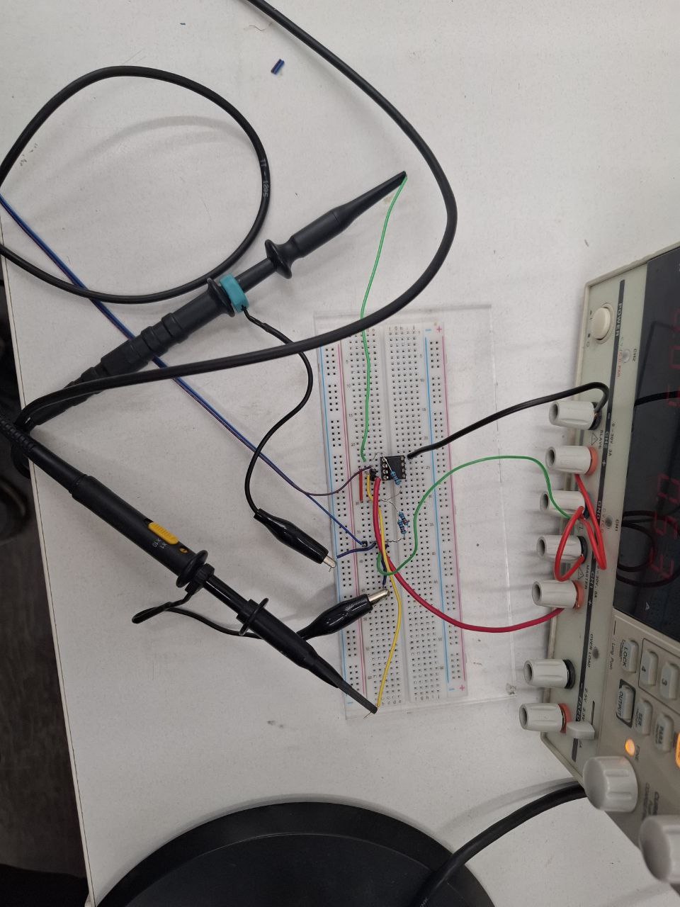
And set scales for A chanel (Input) and B channel (Output)
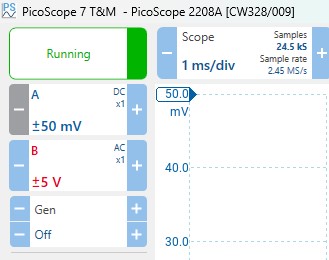
Here is my input signals without turning power supply on
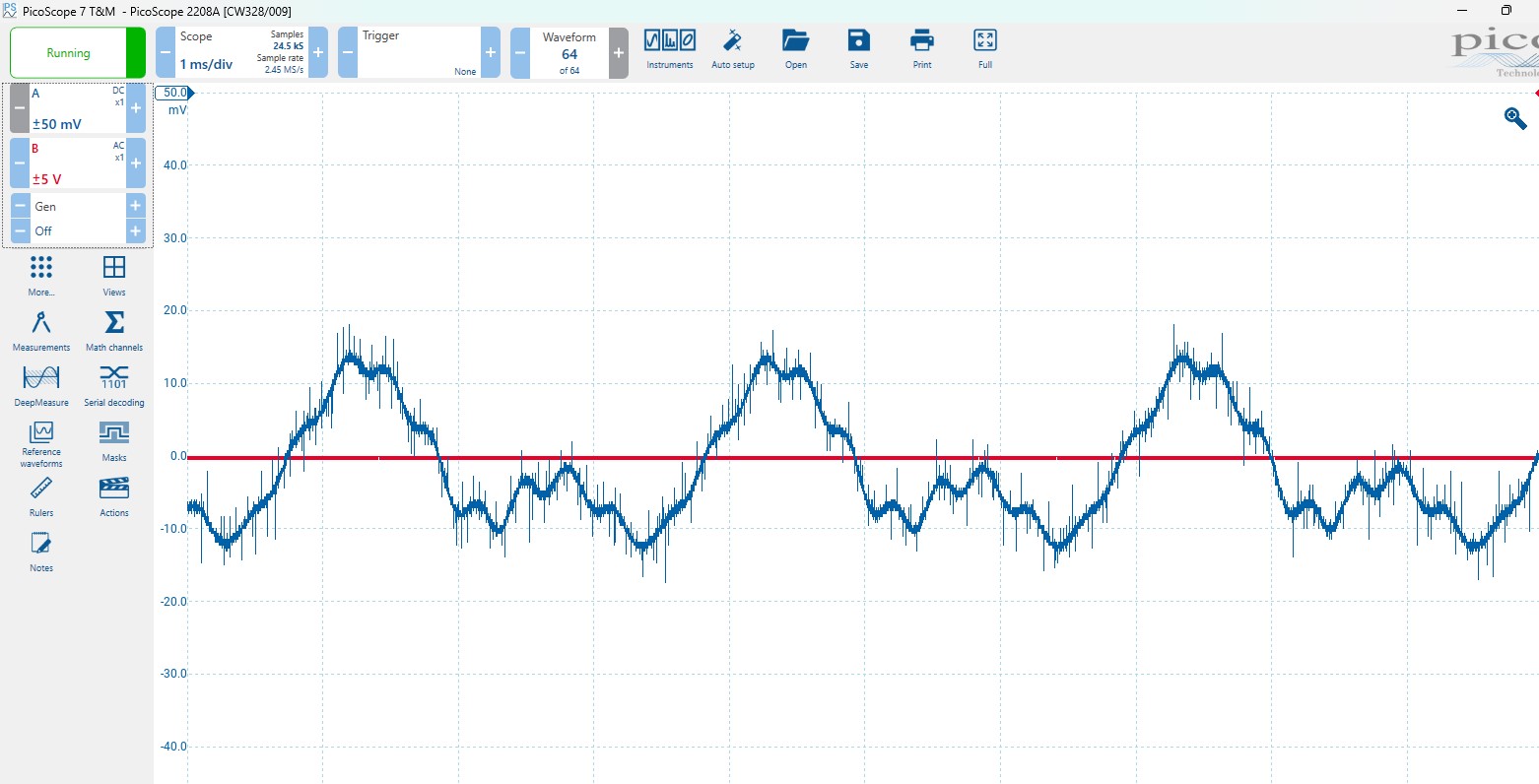
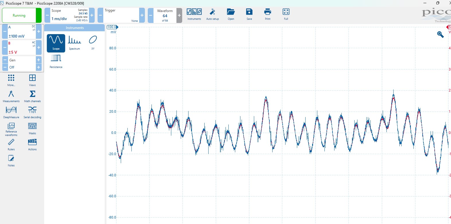
And after Turning it on and changing input signal channel scale to +-100mV, HERE IT IS!!! I have same signal but 50 times amplified))
I want my device to work powered by battery, which can’t give positive and negative voltages necessary for OpAmp work.
To do that I will design Dual Rail Voltage Source Circuit.
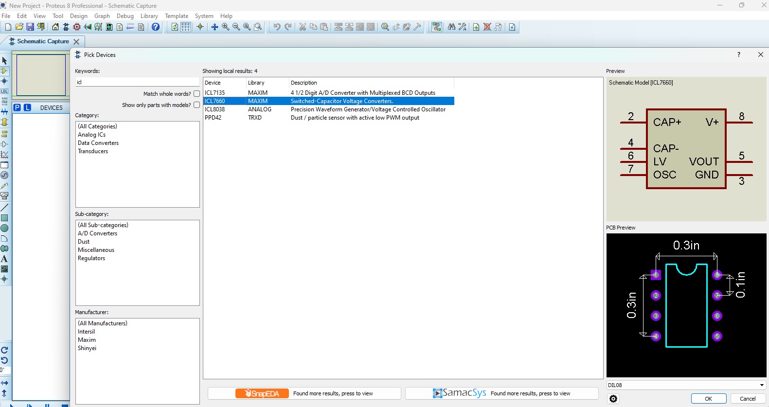
The easiest to make circuit is based on ICL7660 or MAX1044.
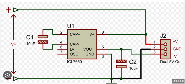
As I don’t find ICL7660 in Multisim, i will simulate that circuit in Proteus Software.
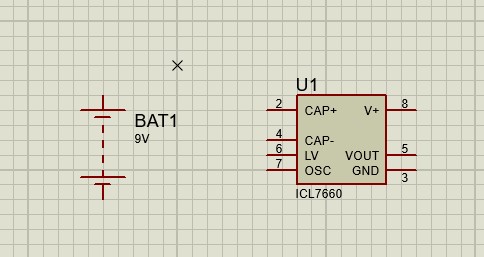
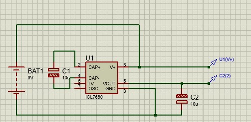
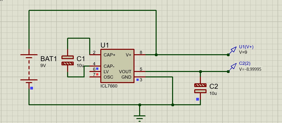
I connected 9V Battery to my circuit
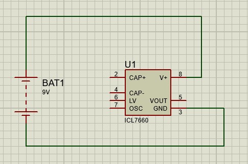
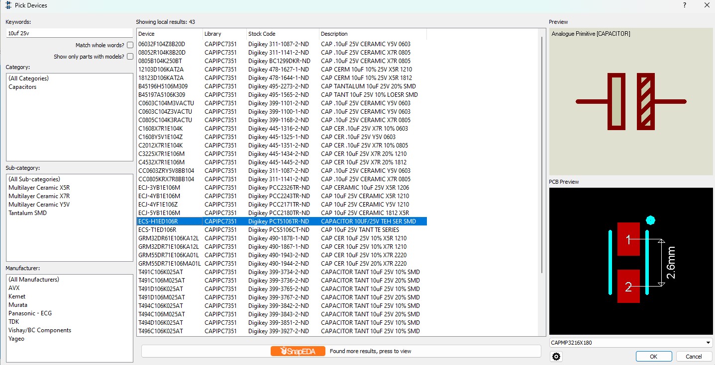
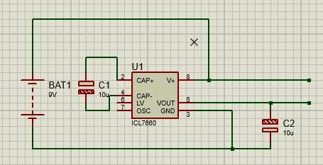
And added Capacitors as given in datasheet
Here is schematics
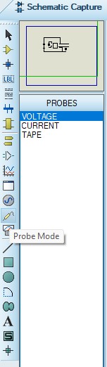
Also I added voltage probes to see Voltage
4.5V and 13.5V ???? Why??
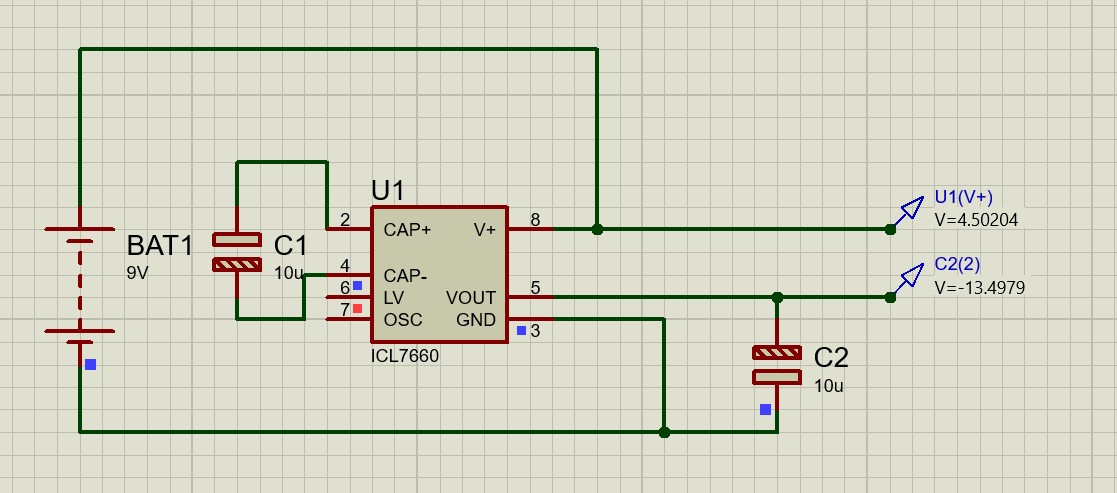
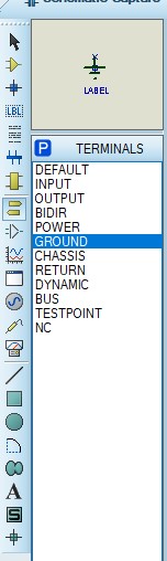
Because i forgot to connect ground
Now everything works fine
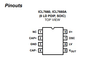
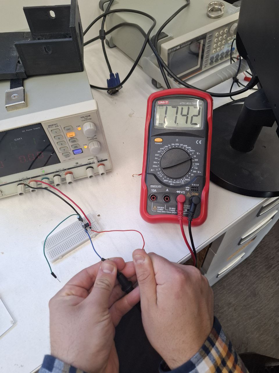
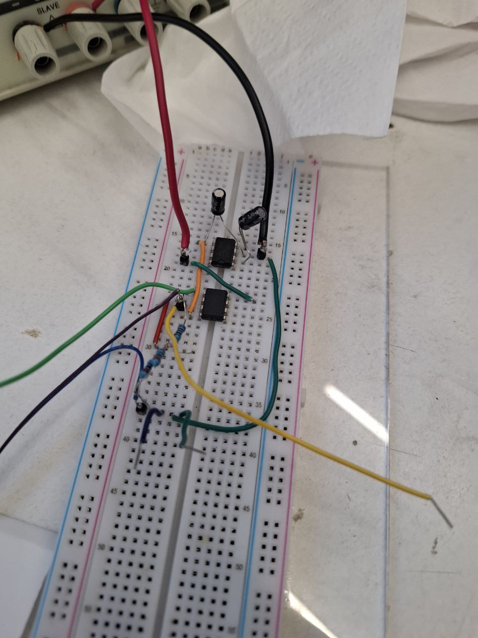
So i started to make breadboard circuit and checked Pinout
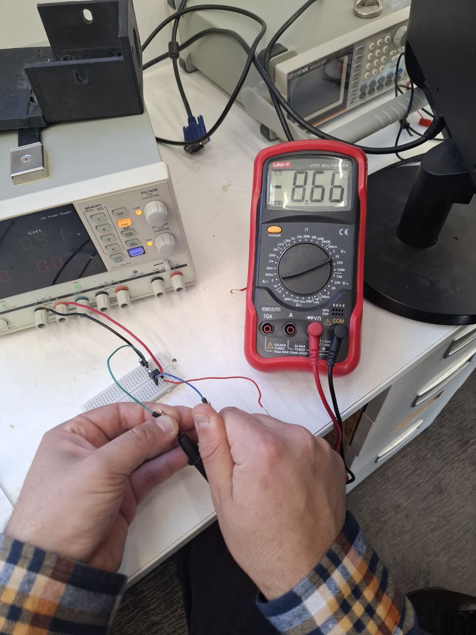
Here you can see that i gave 8.5V from Power Supply
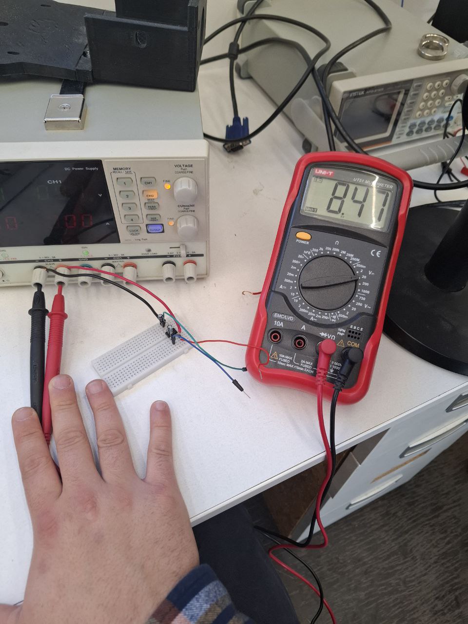
And got Positive and Negative Voltage

I combined two Power circuit with amplifier circuit
And everything Seems fine, until I realised, that it will not work, because I have my amplified signal in range of +-2.5V, but I can’t give it to micro controller, because it only can read positive signal and will damage if i give negative.
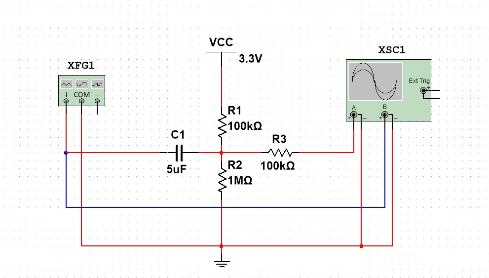
Level Pushing Circuit
So after some research I found circuit that is called Level pushing circuit with capacitor and 2 resistors.
The capacitor cuts off Direct component from signal, and then 2 Resistors that work as Voltage Devider add DC component (Level)
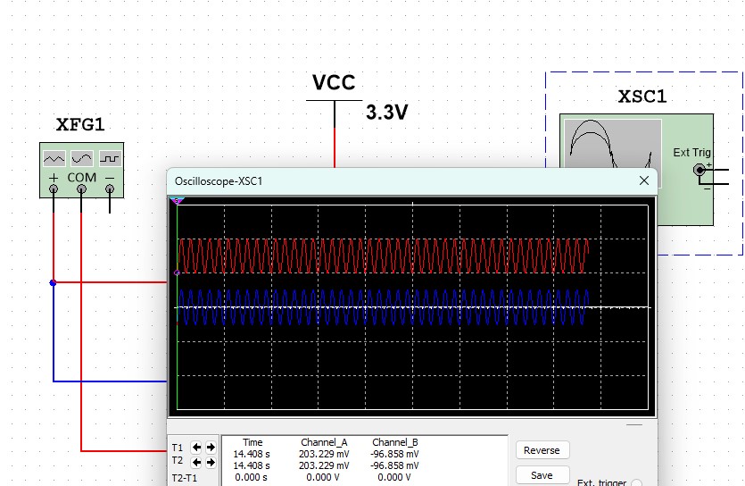
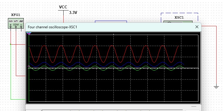
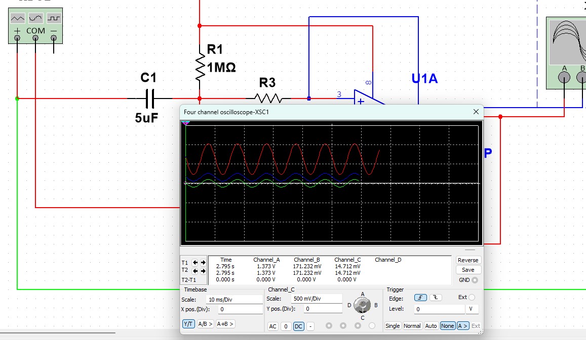
Here you can see same signal before and after Level pushing scheme
And then i understood that now i have positive signal amplified to positive signal, so I dont need positive and negative voltage anymore. So I can use cheaper OpAmp, for example LM358N that every FabLab has.
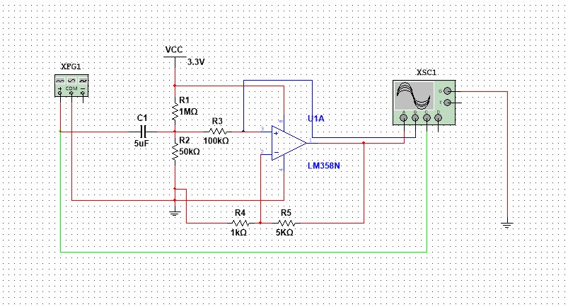
Yes, the circuit works))
PCB Design
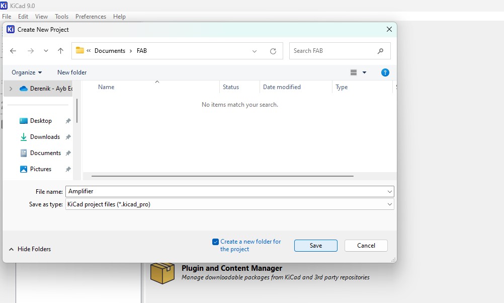
I will make PCB in KiCad 9.0
I started by creating new project
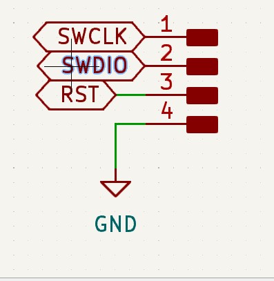
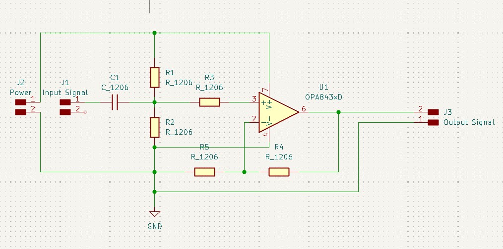
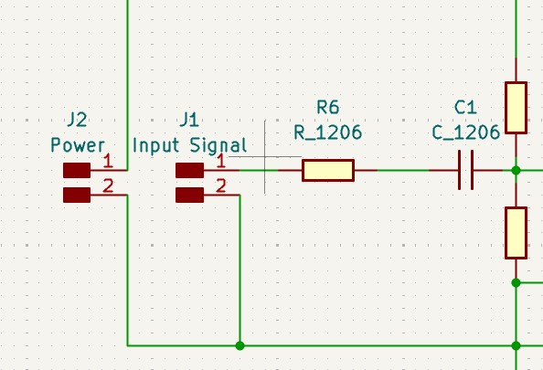
And adding my components to schematic
Here is it
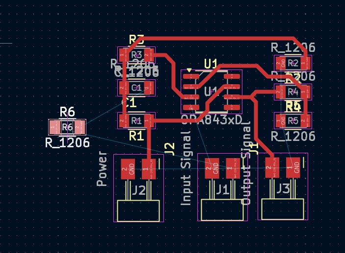
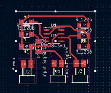
In PCB editor I have them without right placement
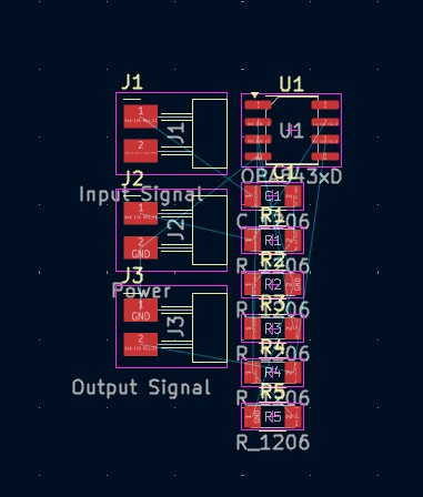
Firstly i placed input , output and power pins
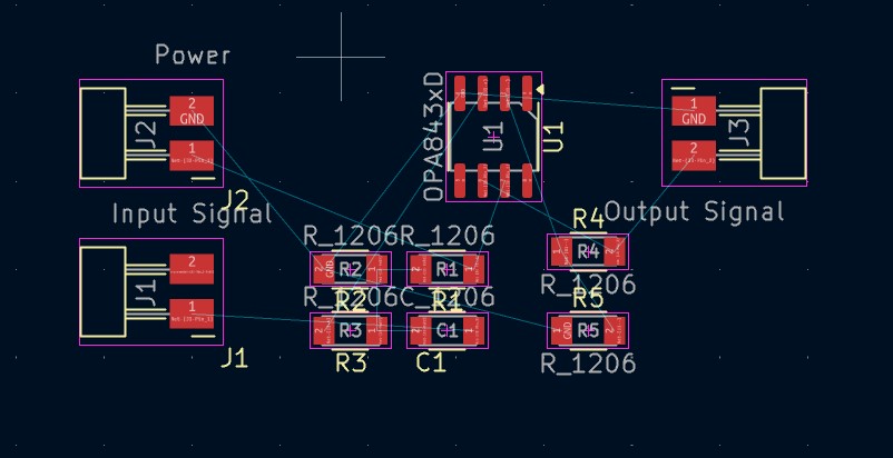
and then components
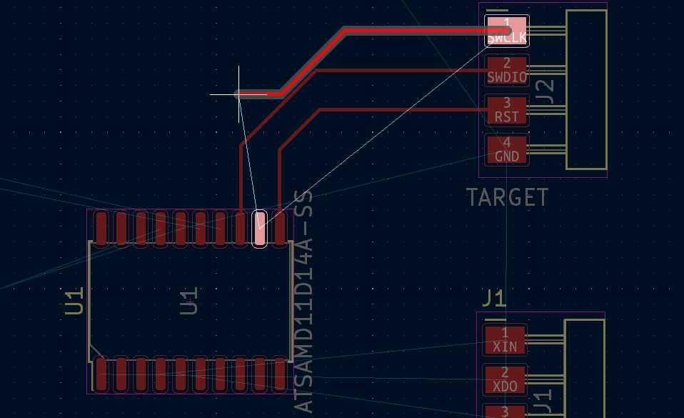
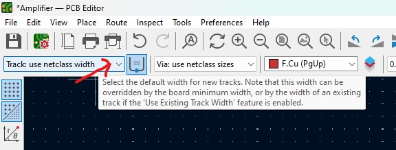
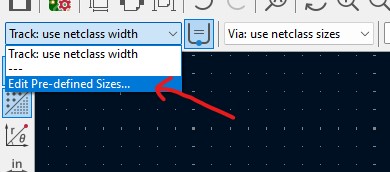
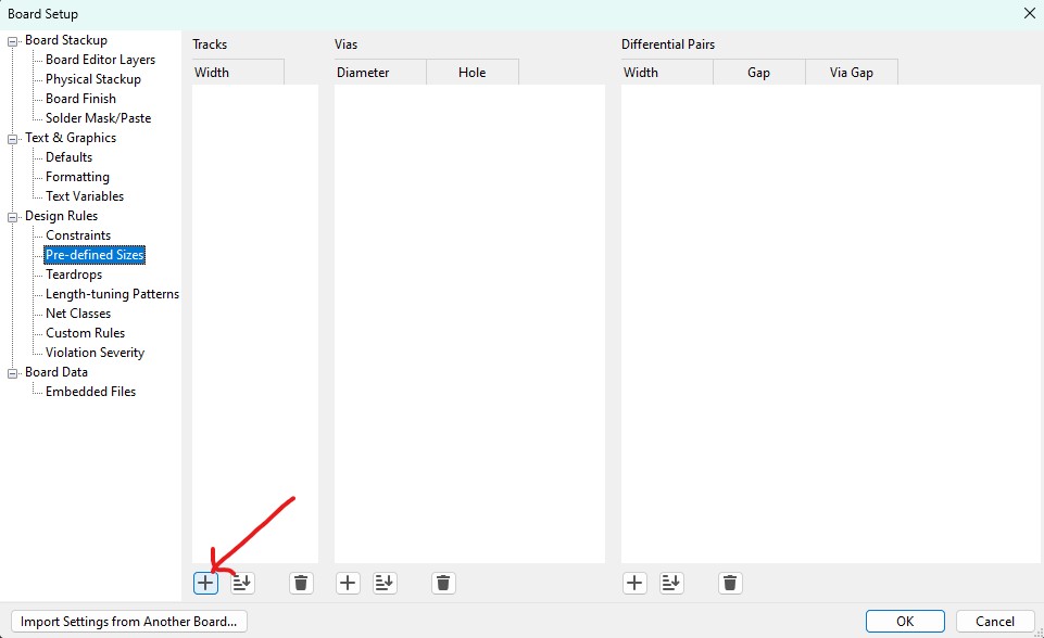
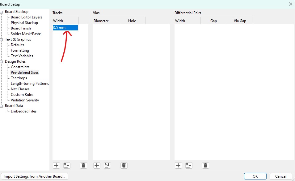
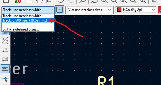
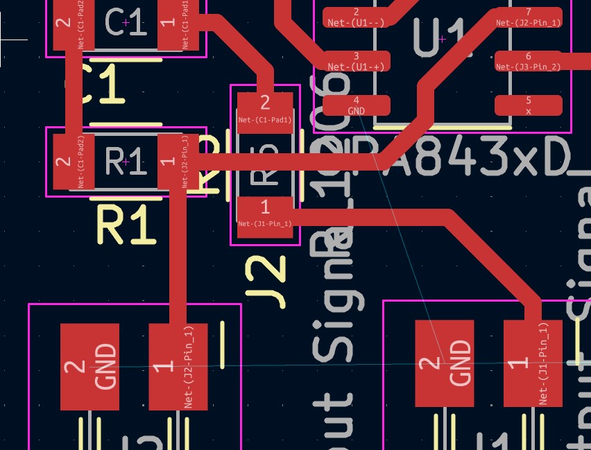
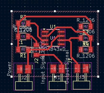
To draw traces I am setting track width that i want
When i was drawing my traces i Found that 1 track can’t be done without intersecting with other tracks
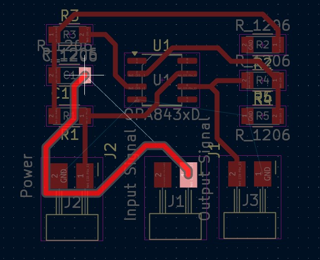
So I added 0 Ohm resistor to that track, which will work as bridge
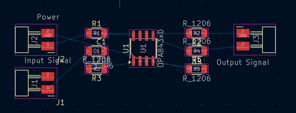
added it to my PCB
Placed and connected
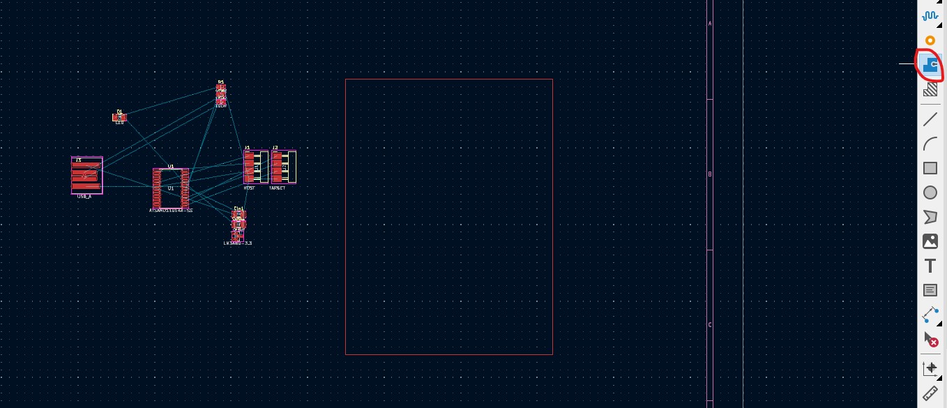
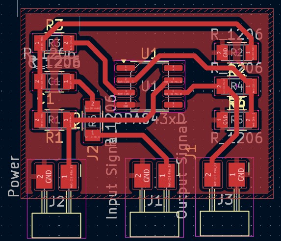
So now it is time to draw outline. I selected Edge cuts layer and drew rectangle
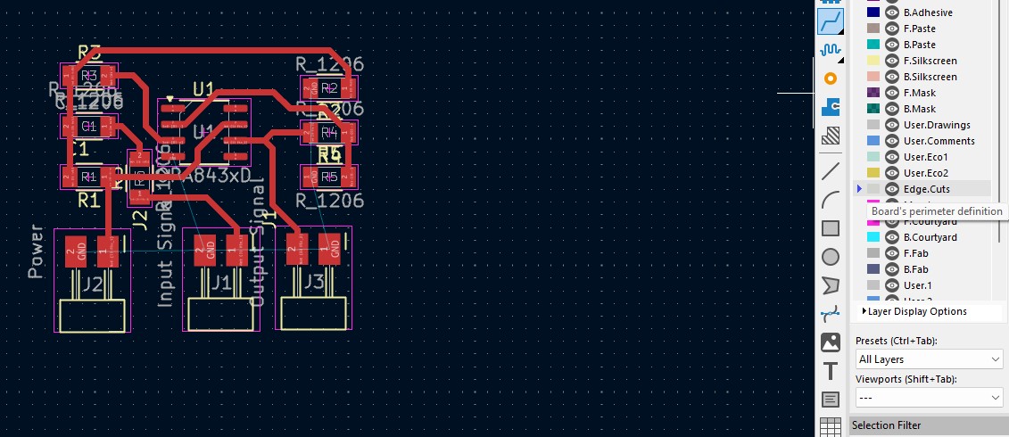
and filled it with GND zone
Here it is))
Helpful Links
Toush Sensor links link_1 link_2
KiCad learning playlist made by DigiKey on YouTube
You can find many useful and interesting information on that channel.
Websites of my instructors Onik and Babken. They did great job, and i learned many from their documentations.
Files
Here is zip file for ATTiny 44 dev board
And Zip file for Amplifier circuit
Conclusion
This week in electronics design, we had a group assignment where we generated code for an STM32 board to produce ramp and sinusoidal signals, which we observed with an oscilloscope. It was pretty cool to see it all in action.
After that, I decided to use a SAMD11D14SS and checked out its documentation to find the information I needed. I also added the FAB library to KiCad to help with the design.
For my PCB, I added pull-up resistors to the D+ and D- pins and made connections in the schematics. I then went to the PCB design and encountered an error that required me to choose a footprint manually, but I managed to sort it all out.
I also wanted to add touch sensors to my PCB, so I did some research and found a touch slide footprint that I added to the design. I even created the symbol for the slide myself!
Finally, I designed an Attiny44a development board and learned how to program it with an Arduino UNO as ISP. It was a bit of a learning curve, but I found some helpful resources to guide me through it.
Overall, it was a great week of learning and experimenting in electronics design!
2025 Conclusion
This week I learned a lot about analog electronics and OpAmps. I used different methods and found one that I need.