Machine Design, Mechanical Design
2023
Group assignment: Making a new CNC (ՄԵՍՐՈՊ)
Finding Details
We had an old printer in our lab, and we decided to split it into pieces, and get some details we can use to build new machine
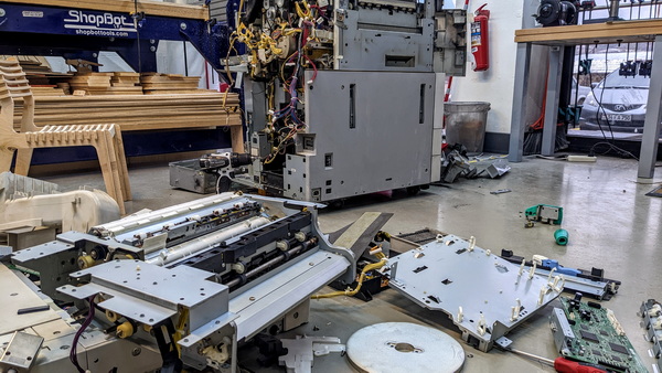
It was unlimited amount of wires and gears inside
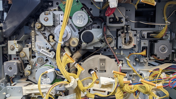
We found many interesting mechanisms there
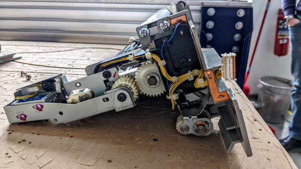
Also we found stepper motors there
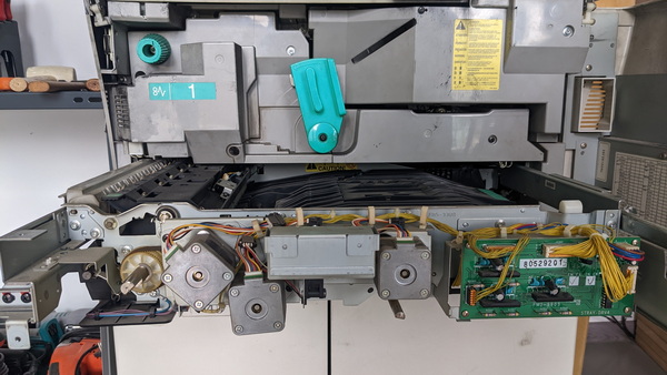
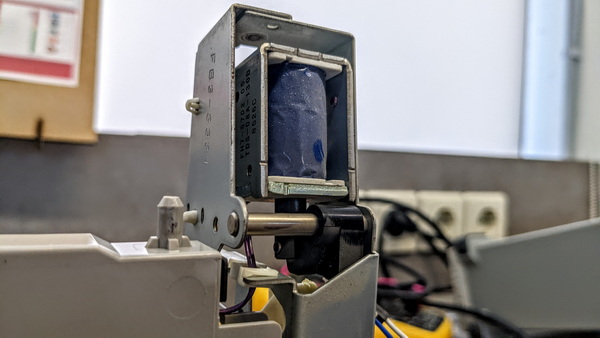
Also we found solenoid, that we made work
NEW 3D Printer
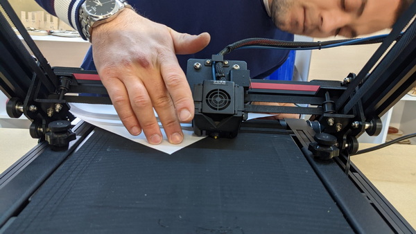
Our Instructor Babken decided to start with assembling New Creality 30 as part of Machine Design week, so we can better understand how machines are assembled, and how they move, and it was very clever decision, because after that we made our CNC really good.
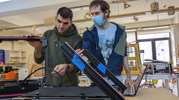
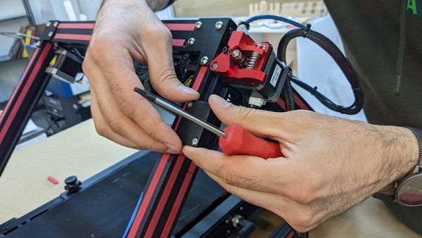
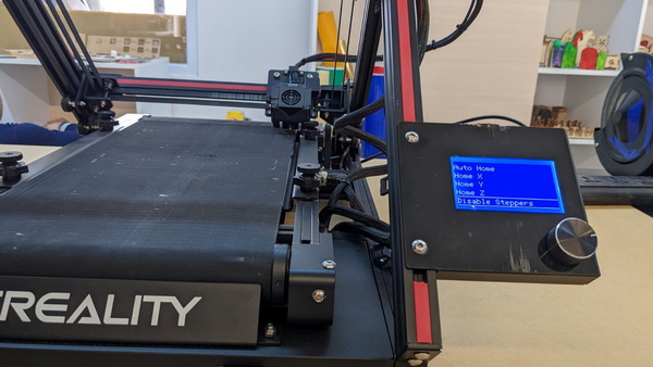
Of corse we had many difficulties with it, and most difficult part was first time setup and calibration
MESROP
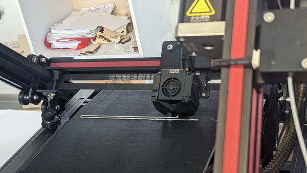
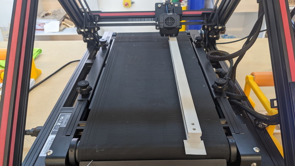
We had to make middle rail of our CNC, so here we used ability of printing long details of our new printer for first time.
As an individual work I decided to make Penholder part.
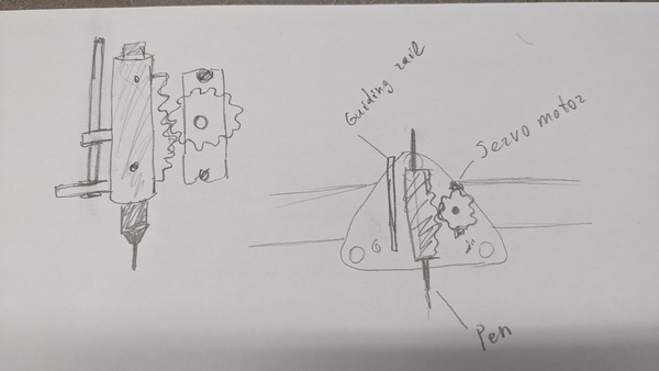
After Sketch I made I started to design my models
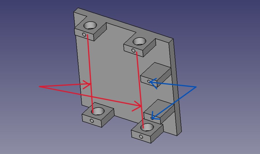
On the Main pain mart you can see a holes that made for servo motor attaching (blue arrows) and holes for attaching rails, that must be used for pen to go up and down (red arrows)
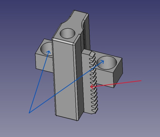
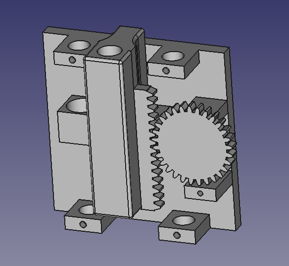
It is the part that pen must be placed in, also it has rack on it (red arrow) (I used Gear Workbench to generate it )
and holes for rails (blue arrows)
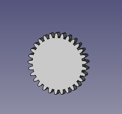
Then I designed Gear that must be attached to servo motor and moves pen up and down (I designed it using same Workbench i used for rack)
But then after discussion with my instructor, we noticed that if servo will push pen to paper, that in can harm pen or servo, so it must have some spring effect, so after short research we found solution in Pinterst that is called Spring Gear, and i designed one
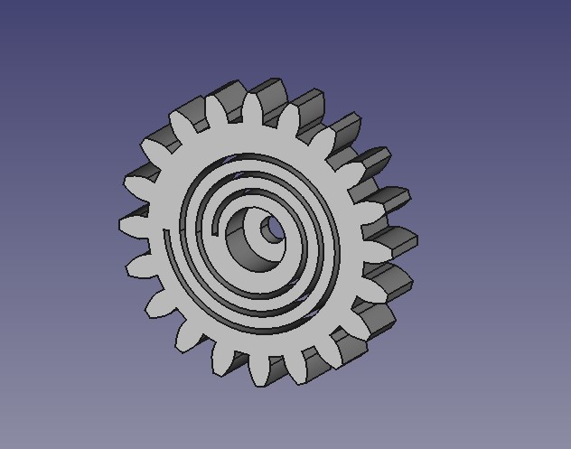
I printed it with different parameters until I found what i needed.
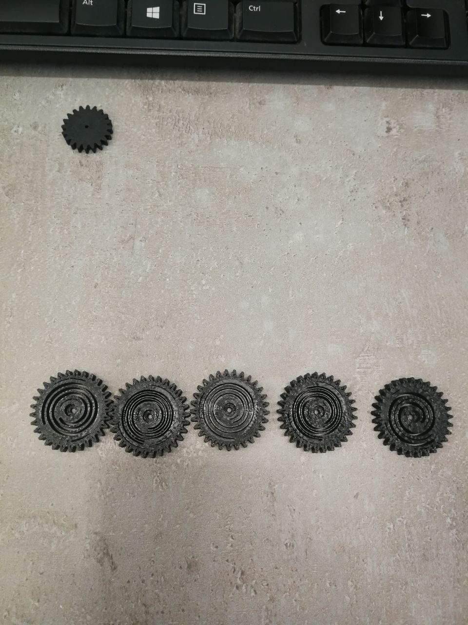
So after All I had something like this
And i started to print parts
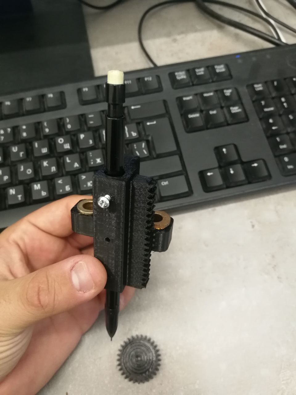
Unfortunatelly we couldnt make my system work, because we had problems with assembling and time left was too short, so we made much simplier design, but to be honest I like my design more ;)
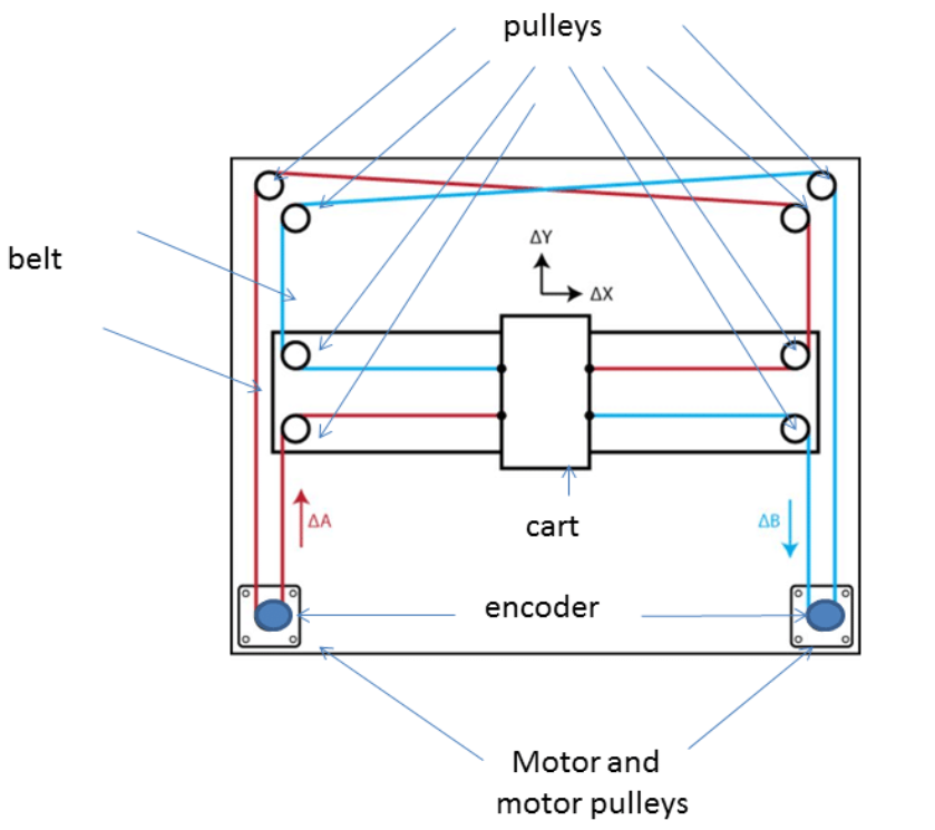
So in our CNC we used Core XY system, because it really easier to make, and it is very interesting.
The CoreXY system is a popular and efficient motion control mechanism commonly used in CNC machines, 3D printers, and other precision applications. It consists of two stepper motors, one for each axis, and a system of belts and pulleys that work together to move the toolhead or print head with high precision and minimal backlash. Unlike traditional Cartesian systems, CoreXY eliminates the need for heavy gantry components, resulting in a lighter and more agile system. It achieves motion in the X and Y axes by simultaneously driving the two motors in a coordinated manner, offering improved accuracy and speed, making it a favored choice for various DIY and professional fabrication systems.
CNC
Then we started to Assemble our CNC parts and making its electronics.
To automate our CNC machine using a CNC shield and GRBL firmware, we followed a detailed process:
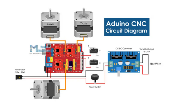
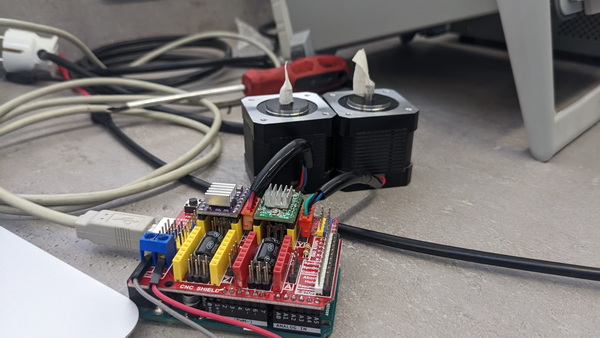
**CNC Shield Integration: We started by connecting the CNC shield, which acts as the bridge between the motors and the control board. This shield enables precise control and coordination of movements.
**Wiring: Carefully following the manufacturer’s instructions, we connected the stepper motors to the CNC shield, ensuring proper alignment and secure connections. The CNC shield typically provides dedicated ports for each motor, simplifying the wiring process.
**GRBL Installation: Next, we installed GRBL onto the control board. GRBL functions as the brain of the CNC machine, responsible for interpreting G-code instructions and translating them into precise motor movements.
**Configuration and Calibration: After GRBL installation, we configured and calibrated the system. This step involved fine-tuning various parameters within the GRBL settings to match the specifications of our CNC machine.
**Control Software Setup: With the hardware and firmware in place, we set up control software. We chose Universal G-code Sender (UGS) for this task, a widely-used software compatible with GRBL. Using UGS, we configured a seamless connection with the CNC shield and control board, enabling us to send G-code instructions and commands to the machine with ease.
Future Development
It is very important to show children and students that making a machine isn’t that hard. Many processes that students do in schools and universisties can be done by machines they can make.Machines can be used in educational purposes such as art, physics and many others. So making machines can become huge step in education.
2025
For this year Machine building assignment, we we automated lathe machine that we had in our Lab, by adding stepper motor control system.
My Task was to make Control and Power Box for machine.
Hardware
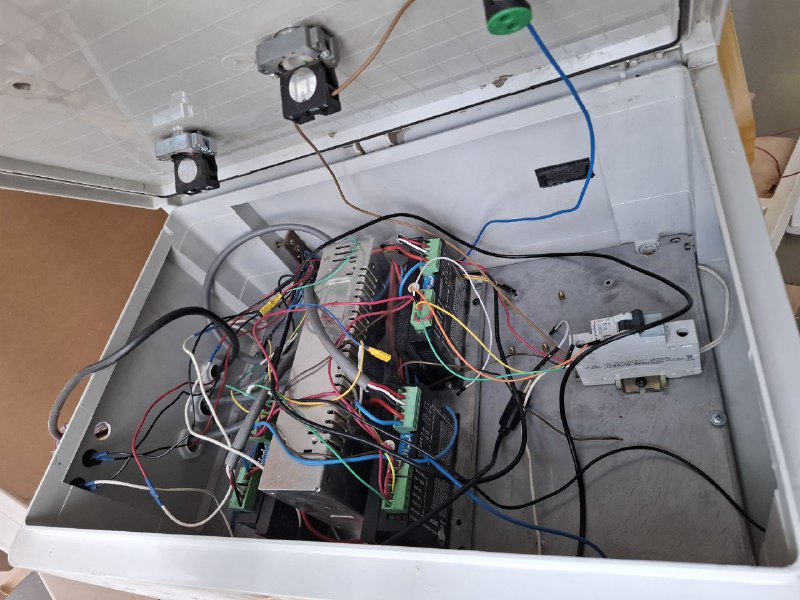
So I started with old CNC control box that I found.
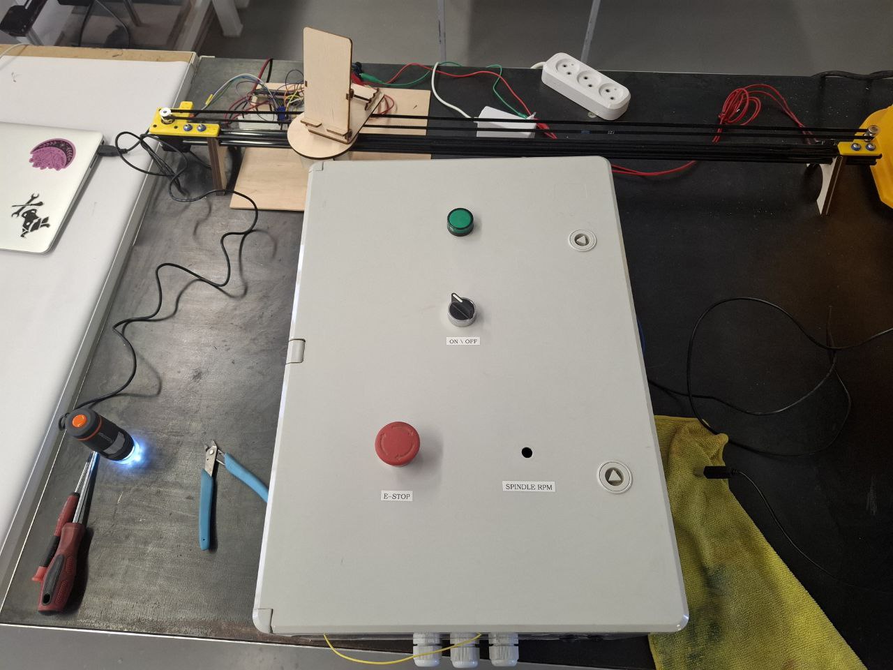
It has Power Safety switches (one NC and one NO), Current limiting block and LED indicator that shows if Machine is powered.
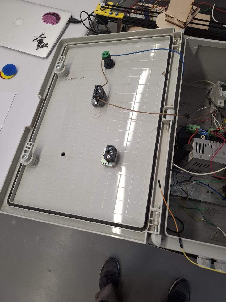
Also it has power supply module (to power Steper motor driver with DC), 2 stepper motor drivers and Arduino UNO with Arduino CNC shield, as control module.
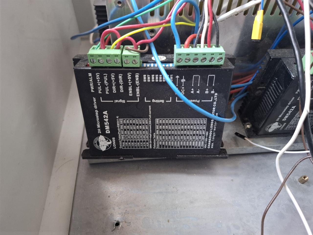
I deattached One driver to check if it is working.
I made test-stand which includes Power Supply - to Power driver, Waveform generator - to give impulses on Step pin of driver, and oscilloscope - to check if given impulses are correct.
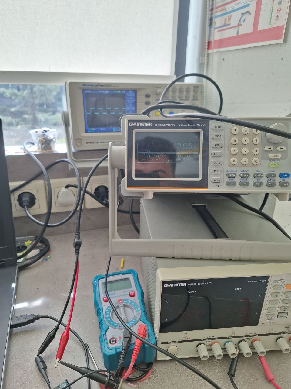
After that I tried to spin with different speeds.
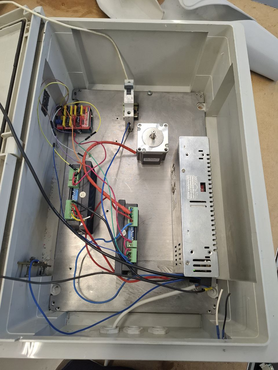
After that I organized Control Box a liitle bit
And started to make program for CNC Shield
Software
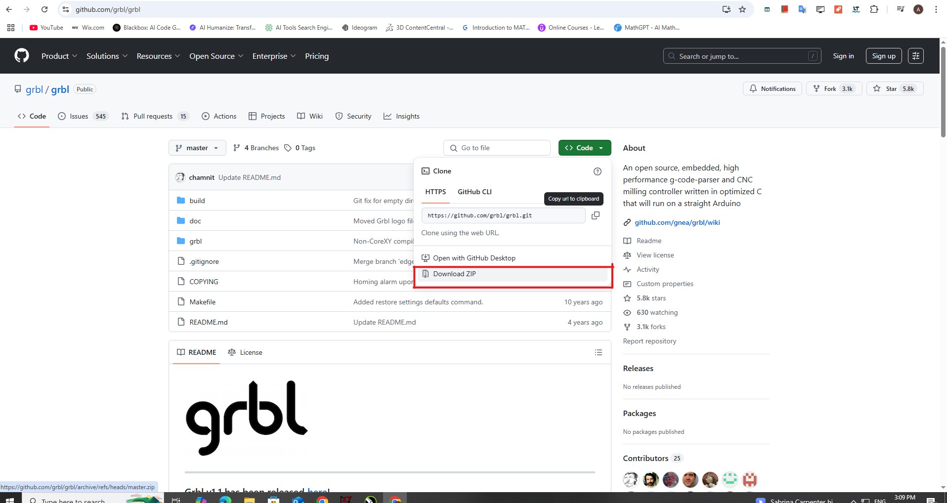
To send G-code to the Arduino for CNC cutting, I first downloaded and installed GRBL, an open-source firmware for motion control
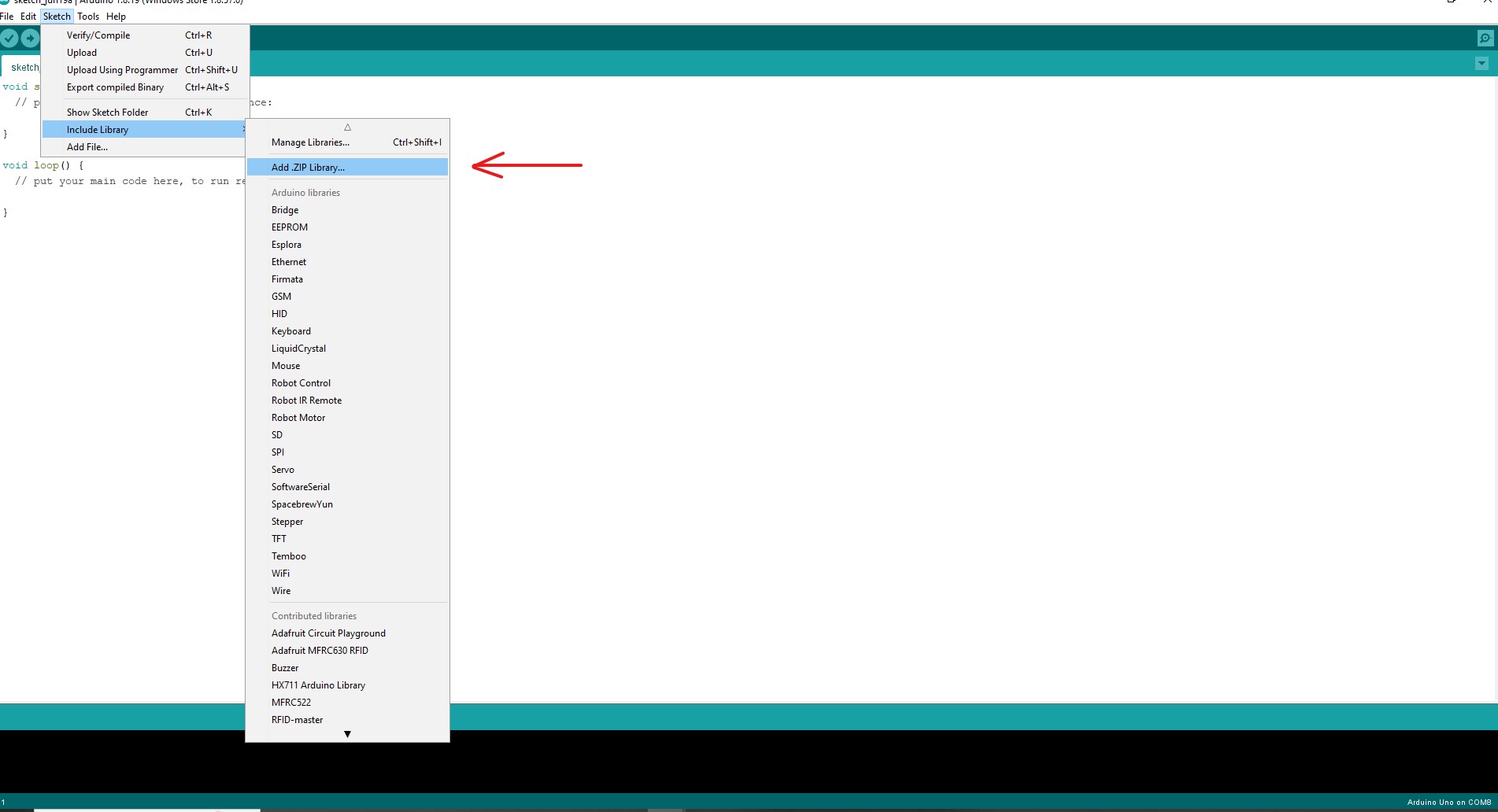
And imported zip file to ArduinoIDE
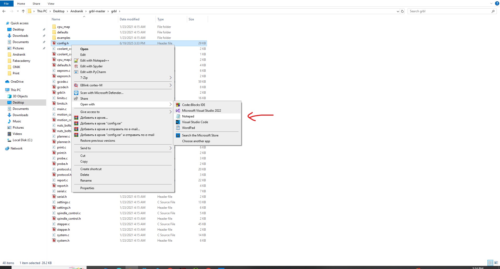
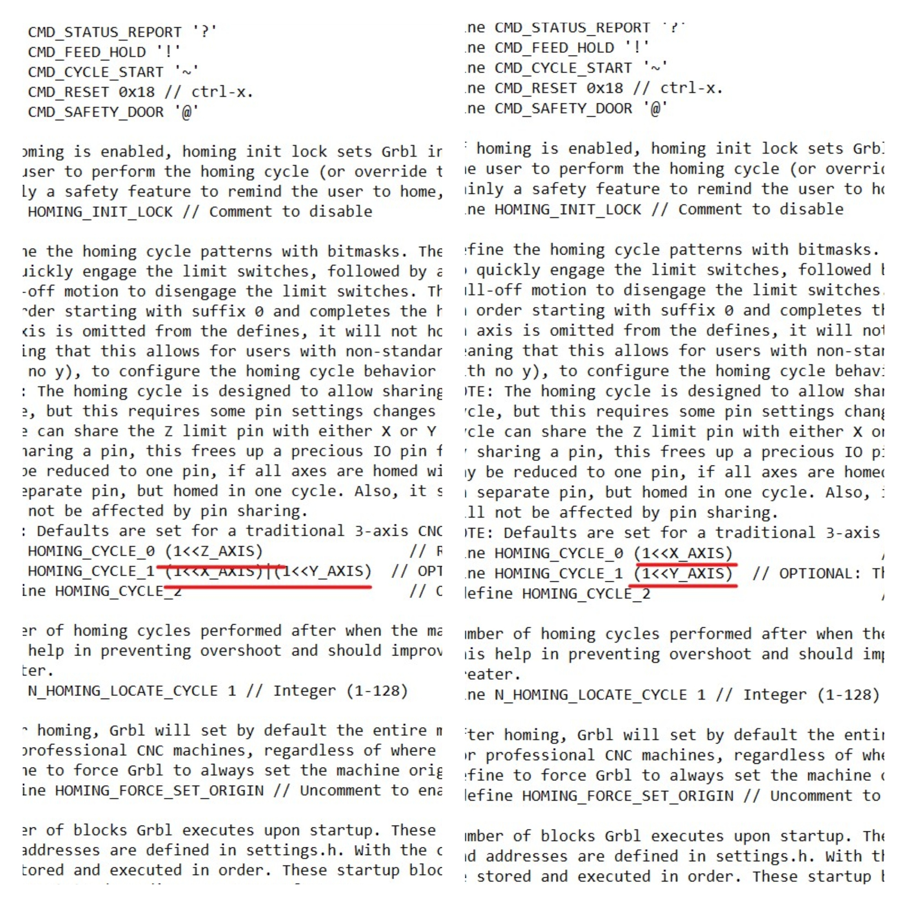
Since my CNC machine uses only two axes (X and Y), I customized the GRBL firmware by editing the config.h file. I opened the file in Notepad
and made two key changes: Renamed the Z axis to X axis in one line to match the machine’s hardware setup.
To send G-code to the Arduino running GRBL, I downloaded and installed Universal Gcode Sender UGS.
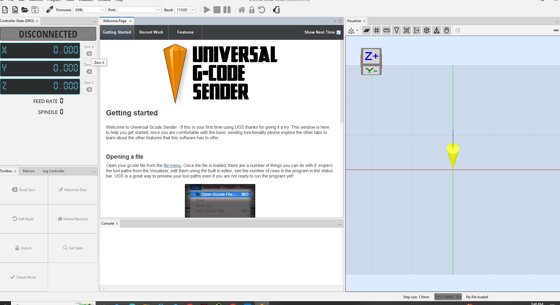
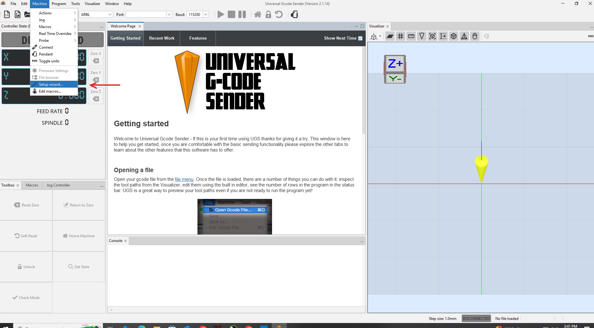
Before starting the cutting process, I needed to set up the CNC machine in UGS. I opened the Setup Wizard from the Machine tab, which guided me through configuring key parameters like axis direction, step/mm values, and homing settings
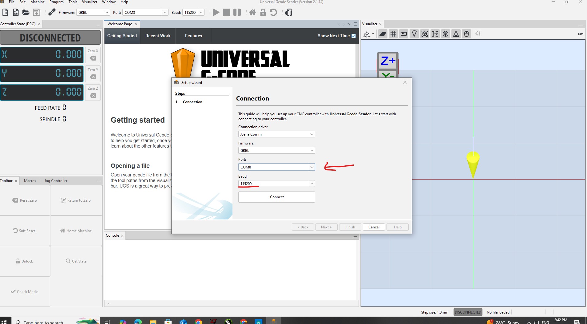
To connect UGS with the Arduino, I selected the correct COM port (COM8) and set the baud rate to 115200, which is the default for GRBL. Once these settings were applied, the connection was established successfully.
I tested the movement and changed the steps per millimeter settings until the machine moved exactly how much I wanted.
Here is it!
You can check whole work we done here
Conclusion
In this project, we designed and built our own CNC machine, focusing mainly on mechanical structure and motion control. We started by salvaging parts from an old printer, then moved on to assembling a new 3D printer and finally built a CNC system using a CoreXY mechanism. Along the way, we also designed a penholder and worked on fine-tuning its performance. There were plenty of challenges during assembly and calibration, but in the end, we managed to integrate a CNC shield, flash GRBL firmware, and set up the control software to automate everything.
I also used the experience I gained back in 2023—working with GRBL and CNC Shields—to build a control system for our lab’s lathe machine. I believe having an automated lathe is a huge step forward for the lab. It makes it much easier and faster to produce repeated parts with precision.