Final Project
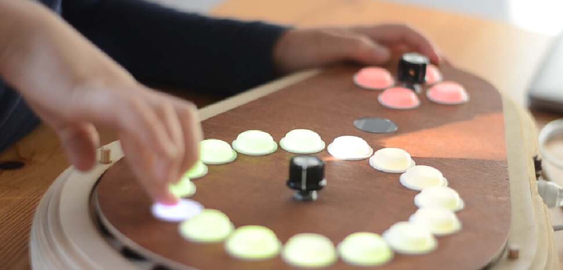
Final project Initial conception (Febuary 2022) Learning to play any musical instrument takes a very long time and a lot of effort. To enjoy music …
We set out to make a zoëtrope machine that would draw it’s own animations. My contributiones were:
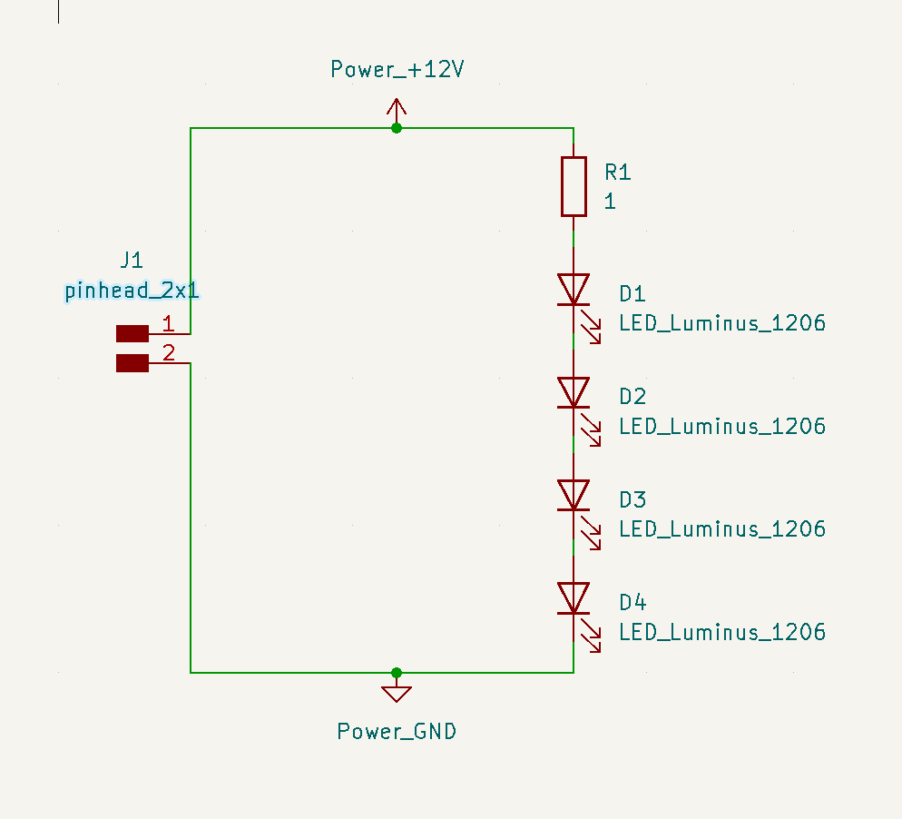
To project any image on any surface we figured our device would need a very bright LED. The brightest LED in the fablab inventory is the luminus MP-3014-1100-50-80. As one of these LEDs can draw 150mA of current, these LEDs should be triggered using a MOSFET.
 |
|---|
| The first luminus board was made with one LED |
 |
 |
|---|---|
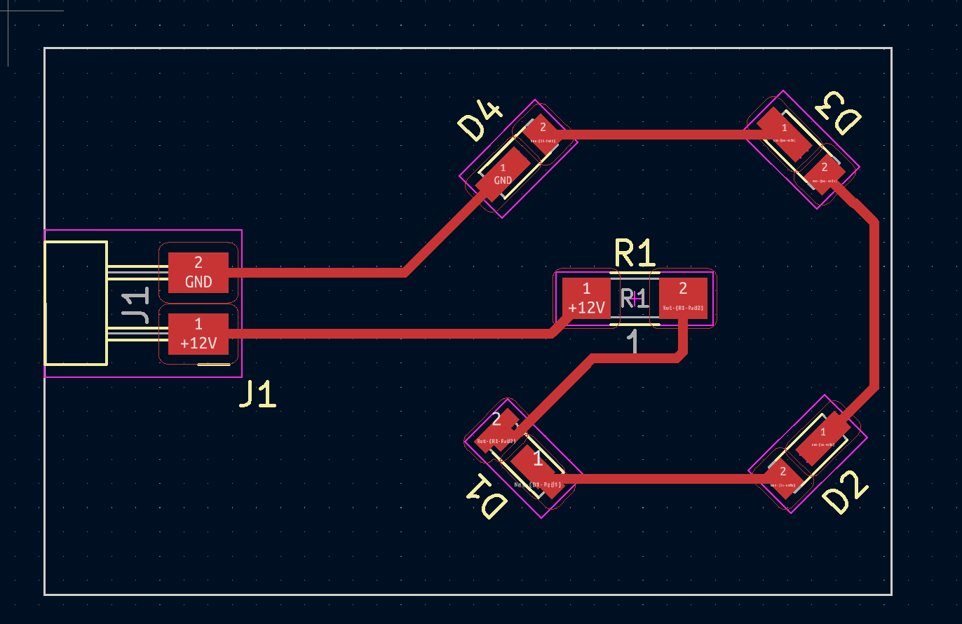
| The second iteration held 4 LEDs. The resistor value was calculated using an online LED calculator |
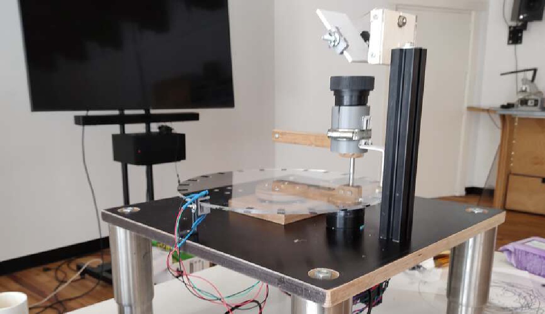
The lamp was held to the bottom of the machine with a lamp-holder I designed. To diffuse the light, half a ping-pong ball was used.
 |
 |
 |
|---|---|---|
| Lamp holder design in Rhino | Lamp holder | Lamp holder with lamp |
The luminus based strobe had to flash only when an image was right before the lens. To determine wether this was the case, markings were made on the transparent disc. When a marking passed a beam of IR light from an IR LED, the beam was obstructed it’s path to an IR phototransistor.
 |
 |
|---|---|
| The design of the sensor holder in Rhino was made to be adjustable in height. | A sudden drop in IR light on the sensor value triggered the strobe |
| The strobe seemed to work in a test setup. |
It turned out just turning on the LED when a marker was registered was too long and resulted in a blurry image. The following bit of code was part of the solution to that problem:
 if (irValue > IR_STROBE_TRESHOLD && lastIRValue <= IR_STROBE_TRESHOLD)
      strobeTime = STROBE_INTERVAL;

 if (strobeState == STROBE_ON && strobeTime > 0) {
      setLuminus(HIGH);
      strobeTime--;
    }
    else
      setLuminus(LOW);
It turns the strobe off after being on for a specific (STROBE_INTERVAL) amount of time.
The firmware consists of:
Most calculations were done using Processing. The application can:
Processing was chosen because it started out as a simulation and visualization of the angle calculation algorithms.
Calculating the angles went according to the following procedure:
For coordinates with a non-zero z-level, the solenoid was triggered to lift the pen-arm.
| Drawing a fish using the control software. |
| Drawing an animation of de Waag using the control software. |
To be able to show an animation we first needed a convenient way to generate one. I wrote a Processing sketch to read a bunch of separate PNG images and arrange them in a circular pattern. The sketch also served as a demo to see if the animations played well.
| A simulation of a rotating Waag on a circular disc |
I am very fond of the way polar drawing bots work. I haven’t seen this setup yet, with a rotating disc and an arm, but I think there are some advantages to such a system. I would really like to elaborate on this configuration, maybe building a 3d printer using this design.
Final project Initial conception (Febuary 2022) Learning to play any musical instrument takes a very long time and a lot of effort. To enjoy music …
What I did. I created the enclosure and designed and milled all the PCBs. TODO Hardware Priority 1 20 x Button LED caps 8x Octave1 8x Octave2 4x chord …