
WEEK 11: MECHANICAL DESIGN, MACHINE DESIGN
For this week my indispensable "fabmate" Jon Merino and I, have to carry out "only" a group assignment, which consists in designing a machine with: mechanisms, actuation, automation and application. At first, everything looked fine because it seems like we have 2 weeks to do this assignment, apart from having time to catch-up (if needed) with previous assignments and continue developing our final project. But, we soon found out that our fablab, as it is within a university campus, closes for 9 consecutive days, so, that leaves us with 3 days of lab access before our regional review, and 4 days before the global session.
But, this situation, far from reducing our enthusiasm, it´s a big challenge boost, that we, definitely, have to take into account when designing our machine!
- So. we plan our accesible fab days as follows:
- First day (thursday 7th of april): Develop our conceptual idea into a machine that is feasible in the time we have, with the materials and machines we have availabe at our fablab and at home.
- Second day (friday 8th of april): Use all the available machines in our Fablab to have as many parts of our machine cutted, lasered and printed.
- Third day (monday 18th of april): Check back again, dismount and mount, in the lab our machine, because we have to finish buiding it at home between saturday 9th to sunday 17th of april.
- Fourth day (tuesday 19th of april): Hopefully, we will just need to improve it, record videos and and check for needed adjustments.
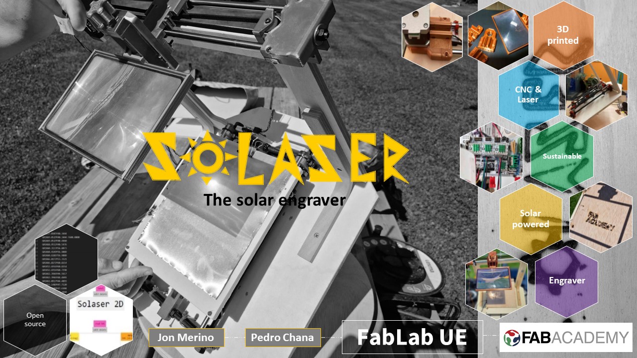
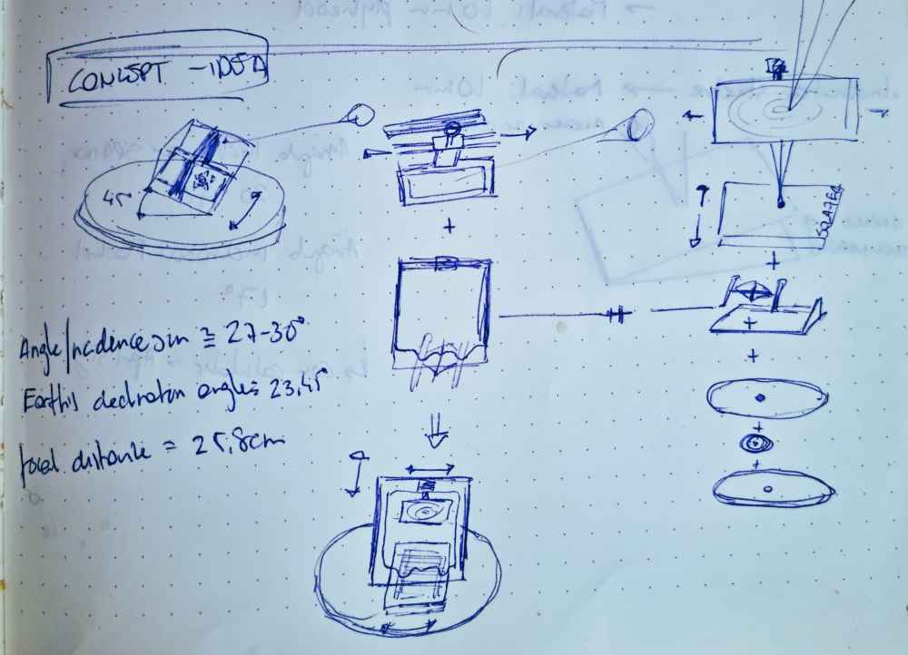
CONCEPTUAL IDEA: SOLASER
Jon Merino, came un with this crazy idea, ¿Why not create a solar engraving/cutting machine with the use of a Fresnel lens..? It sounded incredibly crazy and cool from the begining so, we didn´t have any other choice than to give it a try!. Before even starting our design, we did some research about solar tilt angles, latitudes and fresnel lens:
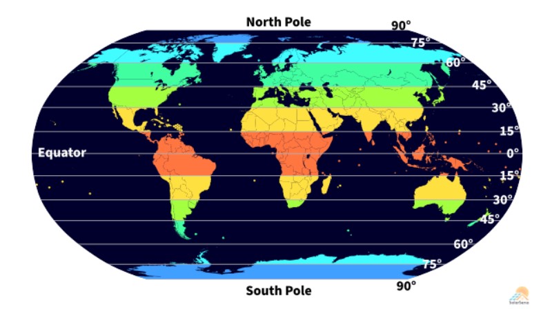
SOLAR TILT ANGLES
We checked in the web for solar tilt angles, and we learned, that in Spain, the optimal tilt angle ranges between 20-40º. To calculate the optimal tilt angle, we used this solar tilt angle calculator for solar panels. And in Madrid, in the month of april, the optimal fixed tilt angle, at mid day. is = 35º. Value to take into account if we were designing our machine in a fixed position. But, as we want to make an adjustable tilt angle base, in our case, the minimum angle would be the one that occurs at the summer solstice. In Madrid, the solar elevation at the solstice is 73 degrees, so the angle of our Solaser would be 90º-73º = 17 degrees. And if we were to use the machine from sunrise to sunset, the maximum angle would be 90º-0º=90 degrees. In other words, the working angle of the Solaser will be from 17º to 90 degrees, although it seems obvious that it will be better to use it in hours closer to noon, also because the sun is more powerful.
 latitude display.
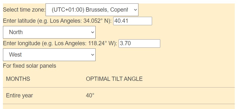 Fixed tilt angle in Madrid.
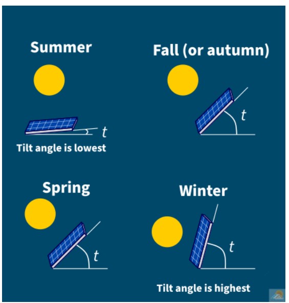 Tilt angle examples.
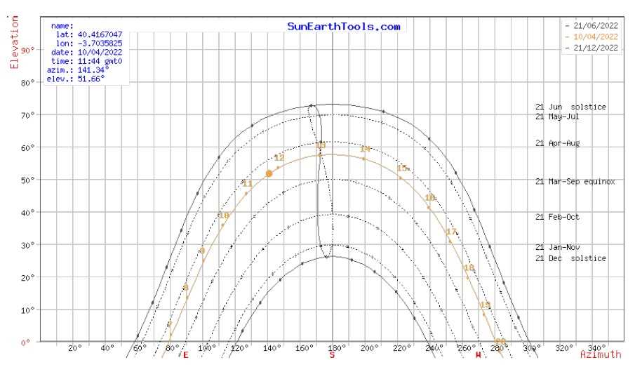 Sunpath Madrid.
FRESNEL LENS
Jon, adquired a very economical Fresnel lens in order to do a test-burn! Fresnel lens are a succession of concentric rings, each consisting of an element of a simple lens, assembled in proper relationship on a flat surface to provide a short focal length. In other words, they´re used to concentrate the light into a relatively narrow beam (just what we need!).
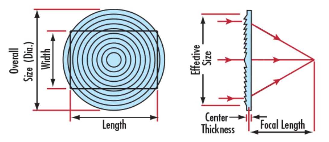
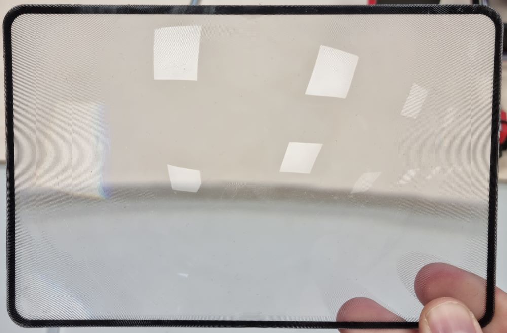 Fresnel lens.
WILL THE FRESNEL LENS DO THE JOB?
The best part of building something, is that you have to try it our first to see if it does what it´s meant to do, so we used a piece of 10mm plywood and our Fresnel lens to do a burn-test that would indicate if this projects can continue or on the other hand it ends here. So, here are the results:
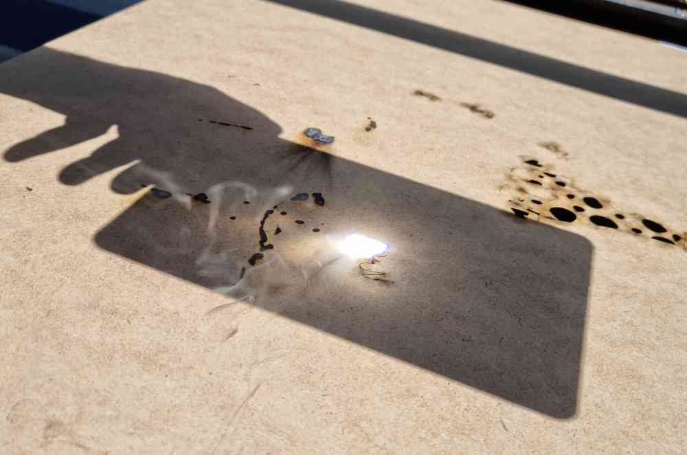 3mm medium density chipwood.
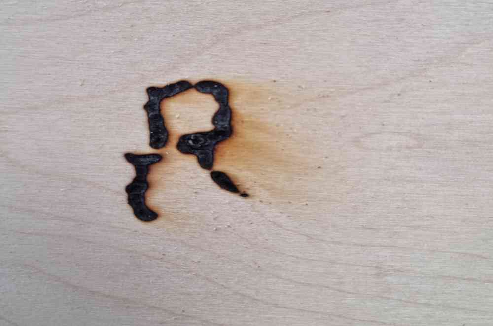 10mm plywood.
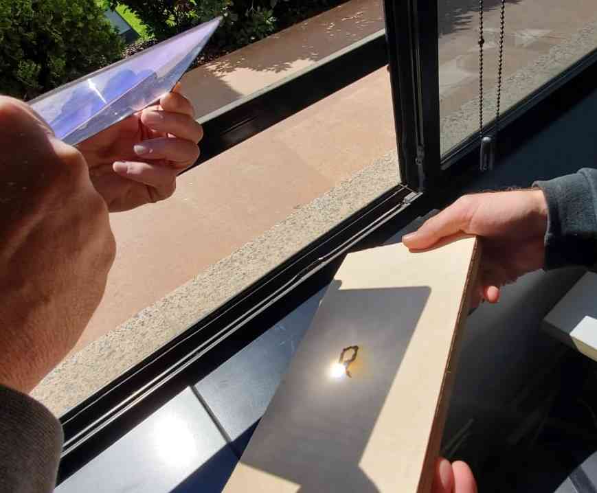
As you can see in the images and video above, the test was a complete success, in a question of seconds, with 25.8cm focus lenght and around 40º of angle tilt, at mid day, we manage to solar burn our 10mm plywood. We also did a test with 3mm medium density chipboar making a hole through it too! Now that we´ve confirmed that our machine can do what we want it to do, it´s time to design it, again taking into account all the issues related before. From now on, we will call our future machine SOLASER, as an abbreviation of Solar + Laser.
DESIGNING OUR SOLASER IN THE FABLAB
As we want to create a sustainable and solar powered machine for a first spiral design, we opted to recycle and use some parts of an old and broken prusa i3 3D printer, use spare 10mm plywood that´s available in our fablab and 3D print some designed parts in PLA, taking into account, as we said before, that we have to plan our design considering the availability of our Fablab, and, as a result, the disposal of materials, tools and machines. And Jon has a 3D printer at home, so in case of breaking or needing more parts, we can print them inmediately.
 First design.
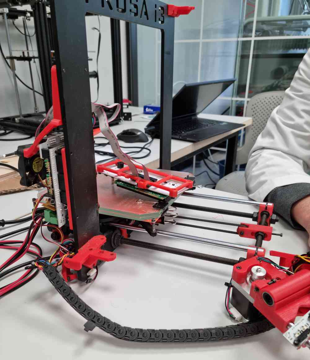 Spare parts from the old prusa.
The machine we want to build has several parts to take into account, and that are going to be developed:
- 1. FRAME + X-AXIS + FRESNEL LENS.
- 2. ROTATORY BASE + ADJUSTABLE BED TILT ANGLE SYSTEM.
- 3. USING RECYCLED PARTS.
- 4. CUSTOMIZING DETAILS.
1. FRAME + FIXATIONS FOR X-AXIS MOVEMENT + SYSTEM TO FIX THE FRESNEL LENS (and its height adjustment):
The first step we took in developing our Solaser, was to create a frame in which to set the fresnel lens, with an adjustable height, fixed to the X-axis movement. In order to achieve it we first designed all the parts in fusion 360 and afterwards, created them depending the materials and tools needed.
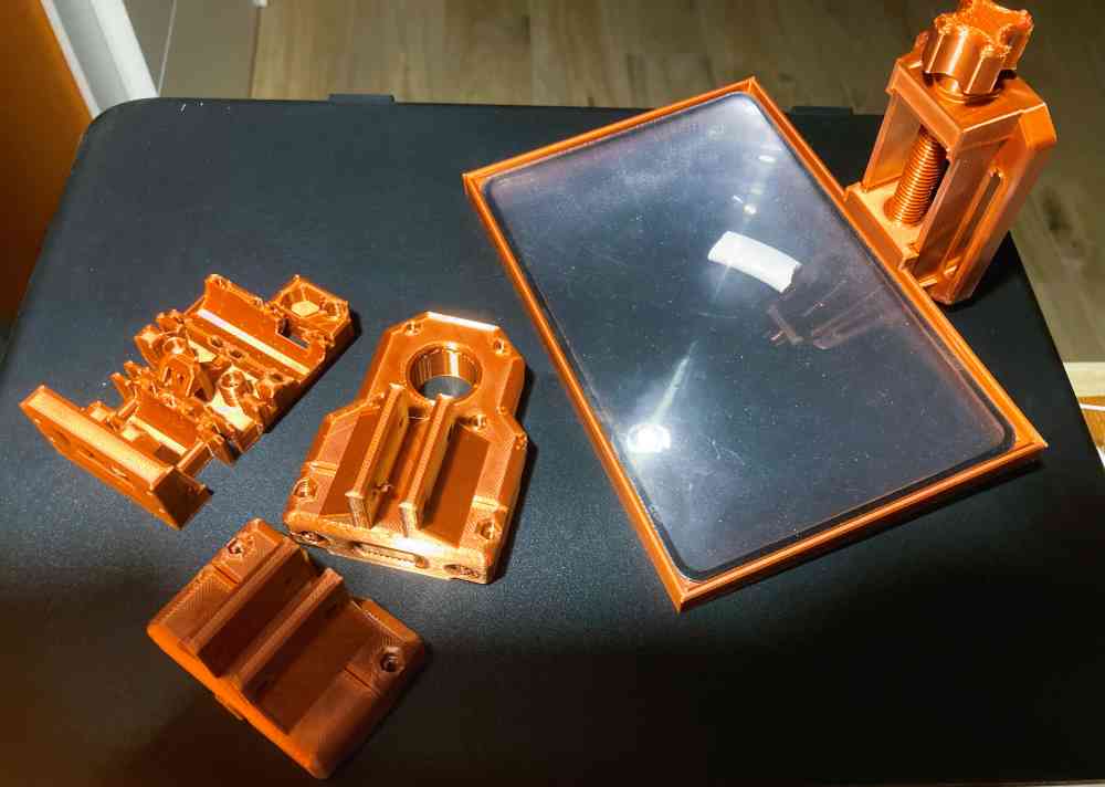
Here you can check the parts that we designed for our machine:
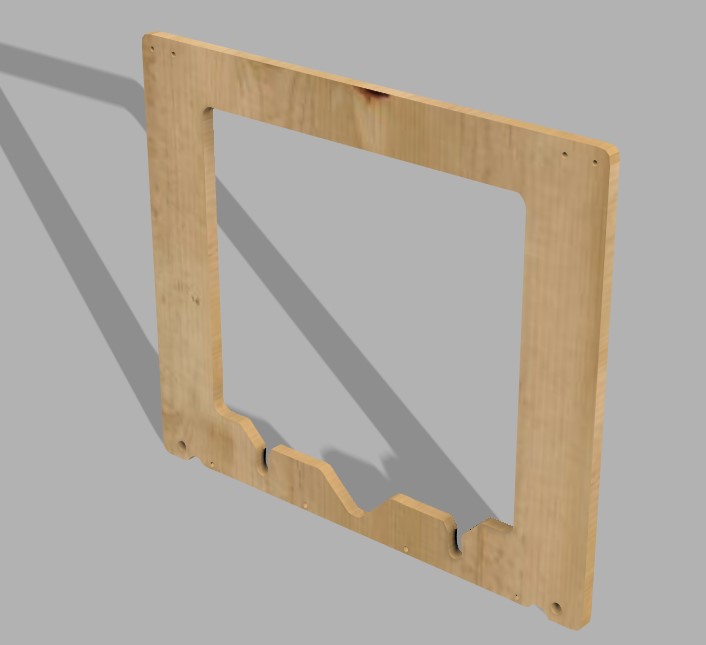 Solaser frame.
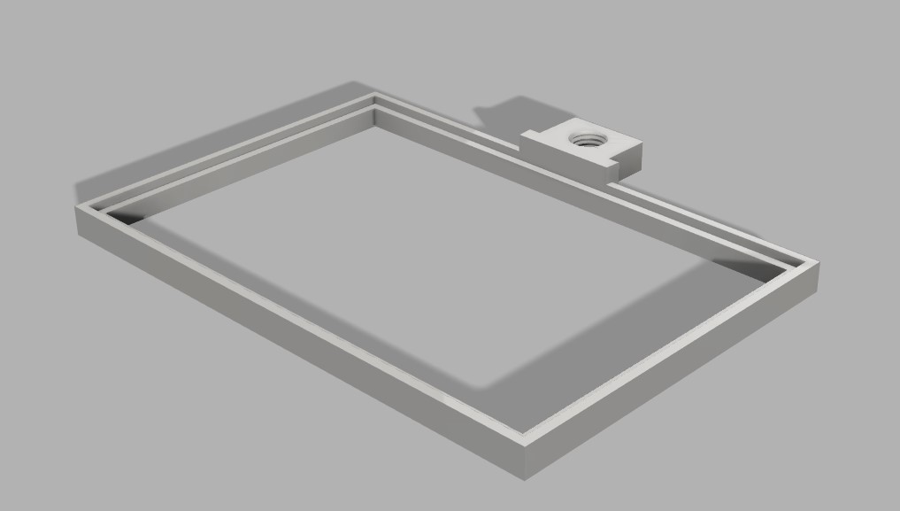 Glass frame.
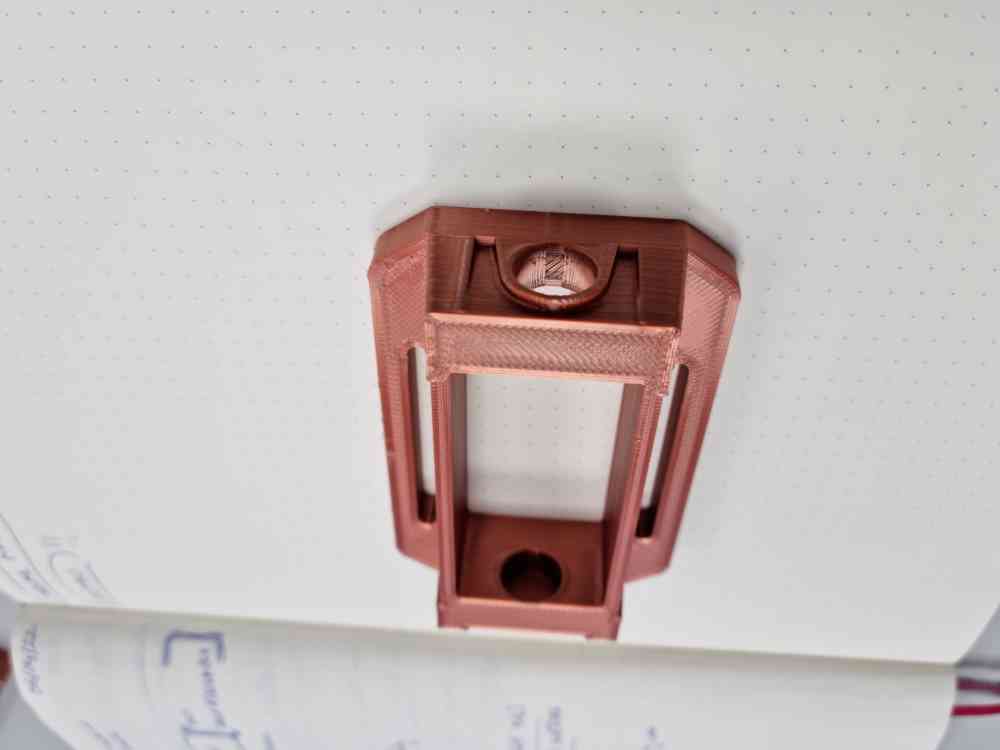
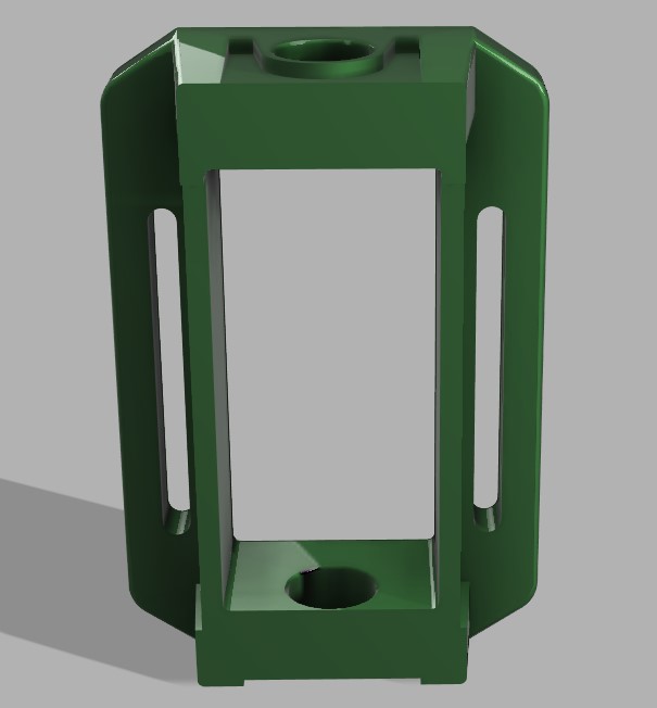 Glass mount.
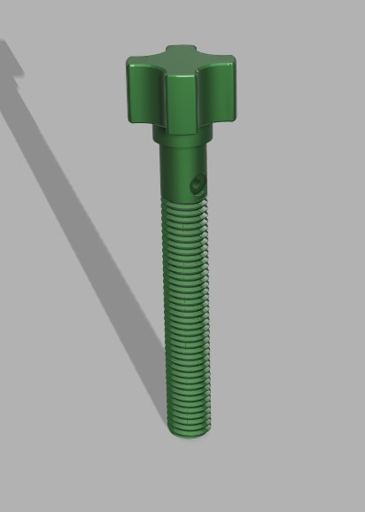 Glass screw.
The following pieces were obtained from internet, but we redesigned and modyfied all of them to fit our needs:
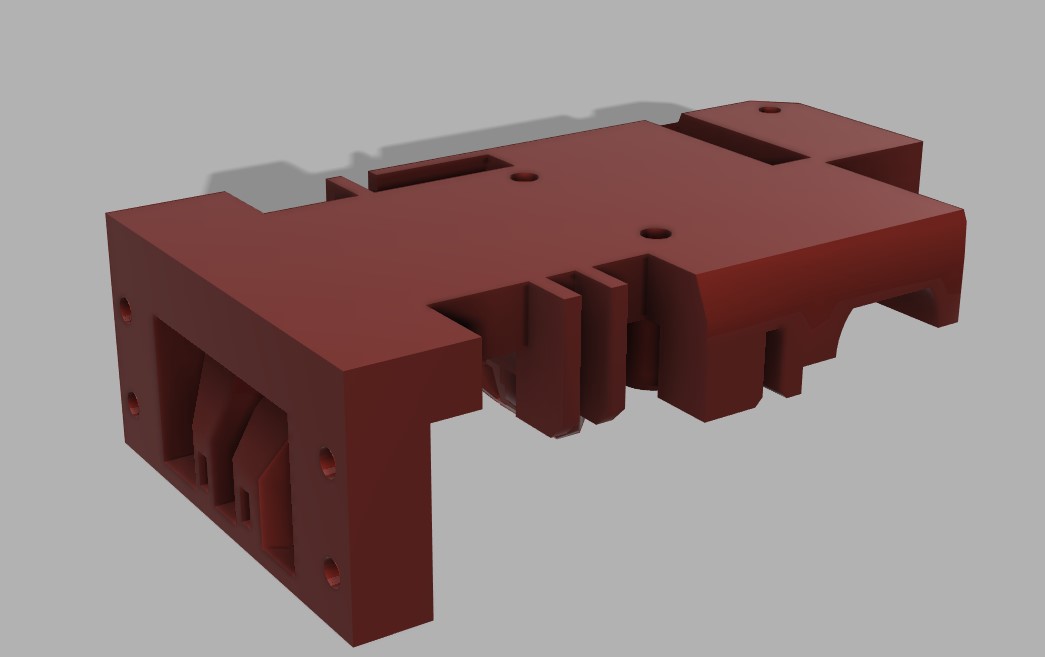 X-axis carriage.
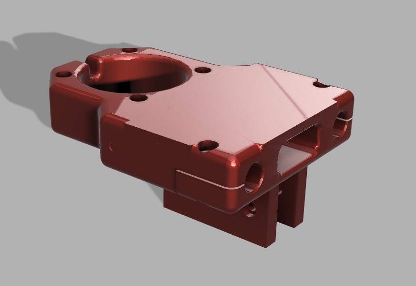 X-axis motor mount.
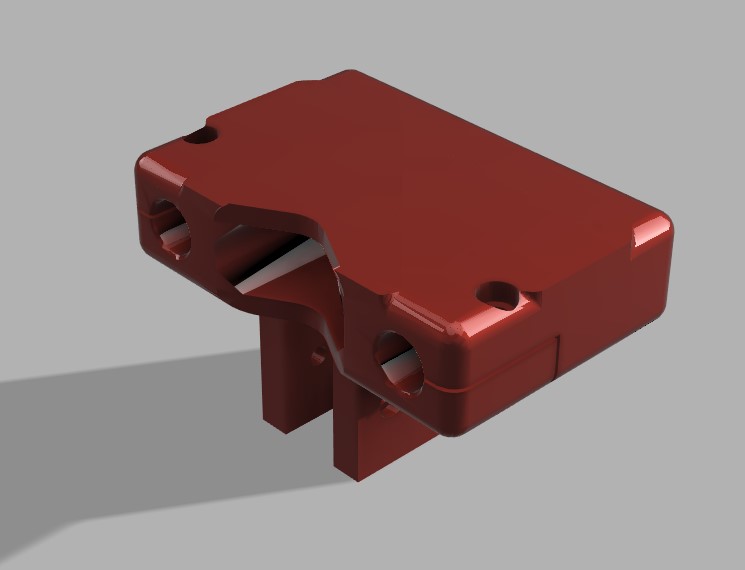 X-axis end.
Here are the links to the pages were we downloaded the original designs, but all of them were modyfied by us: Prusa i3 Hephestos, and Printables both open source. And below, you can see an render image of how it´s suppose to be once the frame is assembled with the X-axis pieces.
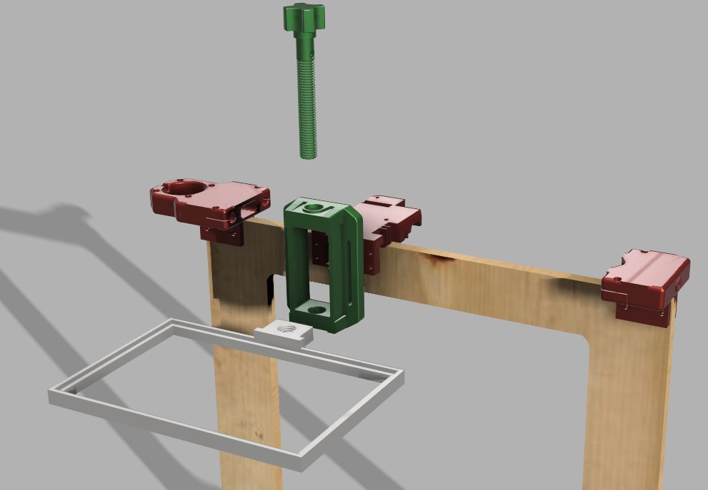
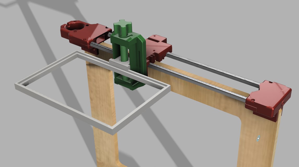 Frame mounted.
In order to "create" the parts shown above, we used the following tools and materials:
| MATERIAL AND TOOLS TO USE | DESCRIPTION |
|---|---|
| 10mm plywood board | Creating the design in Fusion and programing our milling in RhinoCAM. |
| Fixations for X axis movement with PLA | Modifing a downloaded design in Fusion 360 and 3D printing with 100% infill. |
| Design the system to fix the Frensel lens to the frame with PLA | Design in Fusion 360 and 3D printed. |
| Recycle rods, motor and movement belts + combine them with our 3D printed parts. | Obtain the parts needed from the old prusa. |
For this first part, we used the CNC milling and the 3D printers in order to have our plywood frame, and the fixations needed for our X axis system, combined with our Fresnel lens fixation. To be able to do it, we applied the knowledge learnt in printing, and in computer controlled machining weeks.
3D printing in our Fablab
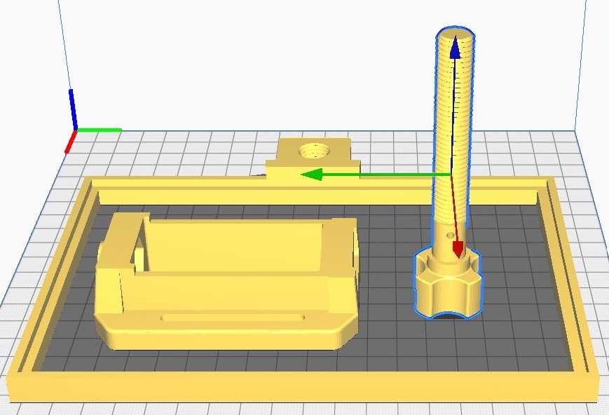 Ultimate Cura
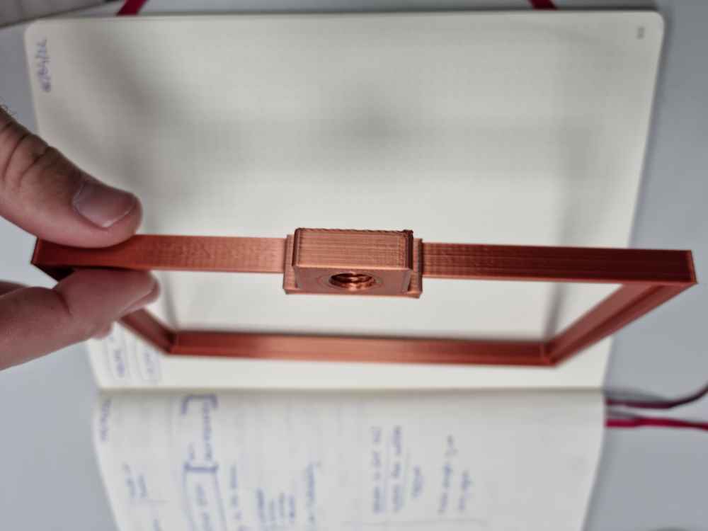 Printed parts
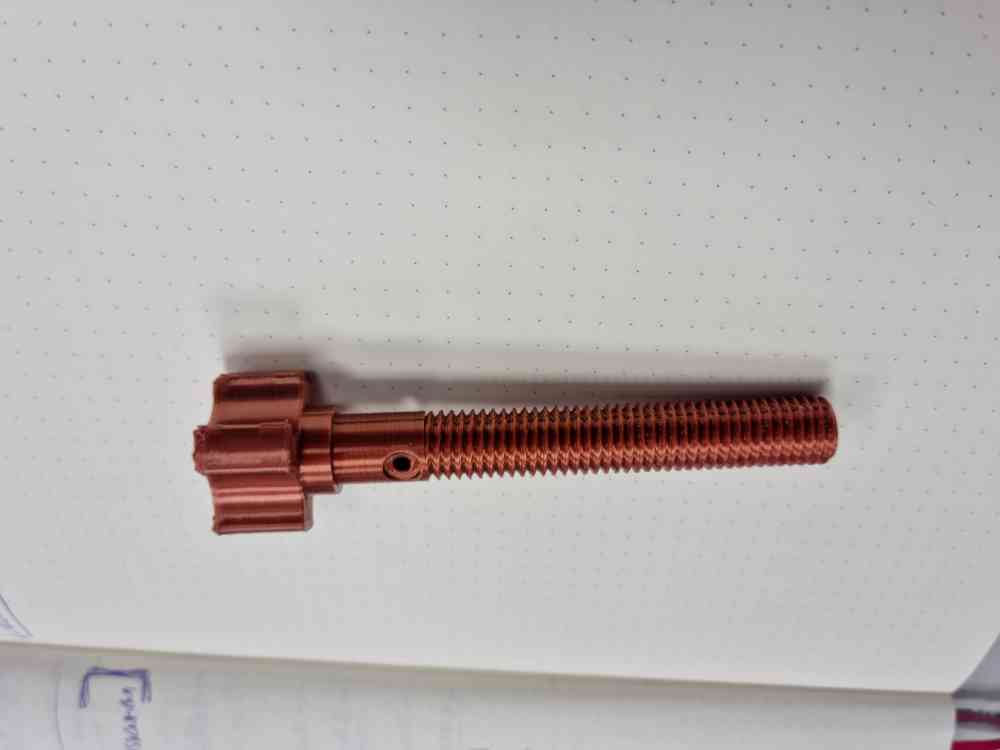
Above you can see some of the parts that we 3D printed. After some errors (as you can read later) we opted for a nearly 100% infill.
CNC Milling in our Fablab
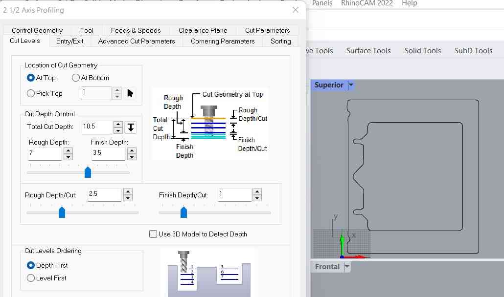 RhinoCAM
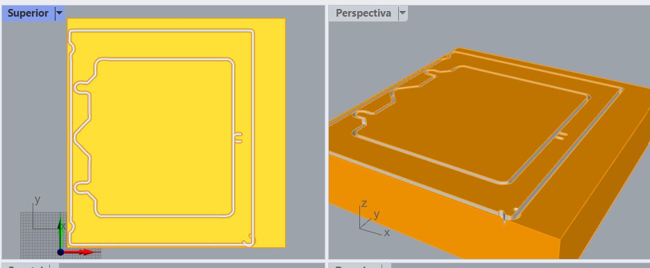 Simulating
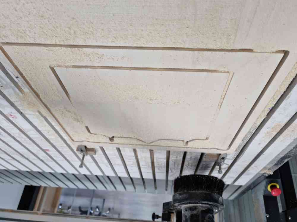 Cutting the frame
For the CNC milling, we used a 6mm diameter flat tool for a 2D milling. In this case, we used both the frame, and the inner part of the frame as the bed of our Solarser.
Here you can check some videos of how it went:
DOWNLOAD FILES: Frame and X-axis 3D parts
2. ROTATORY BASE + ADJUSTABLE BED TILT SYSTEM
Once finished with the frame and X-axis parts, we worked in the second part of our Solaser. For this second part, we created a plywood bed from the inner part of our milled frame plywood spare part, and a adjustable tilt angle system that goes underneath the base (attached to the frame), all on top of a rotatory platform. To carry it out, we decided to use the following materials and tools:
| MATERIAL AND TOOLS TO USE | DESCRIPTION |
|---|---|
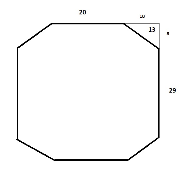
| 10mm plywood board + CNC Milling | Creating a wodden base ,29x20cm with 13cm chamfers, to mount the Y-AXIS made from the prusa´s recycled parts. |
| 10mm plywood board + CNC Milling | Creating two 50cm diameter circles design and programing our milling in RhinoCAM with a 6mm diameter tool. |
| Laser cut a 20cm diameter circle in 3mm methacrylate. | That will be set between the two 50cm diameter circles, so they can spin manually. |
| 3D printing PLA | A bolt and a nut to fix the plywood rotatory base + methacrylate circle. |
| 3D printing PLA and a 60cm threaded rod | 3D printed two axis rotation speaker wall mount from internet and combined it with our rotatory platform and threaded rod. |
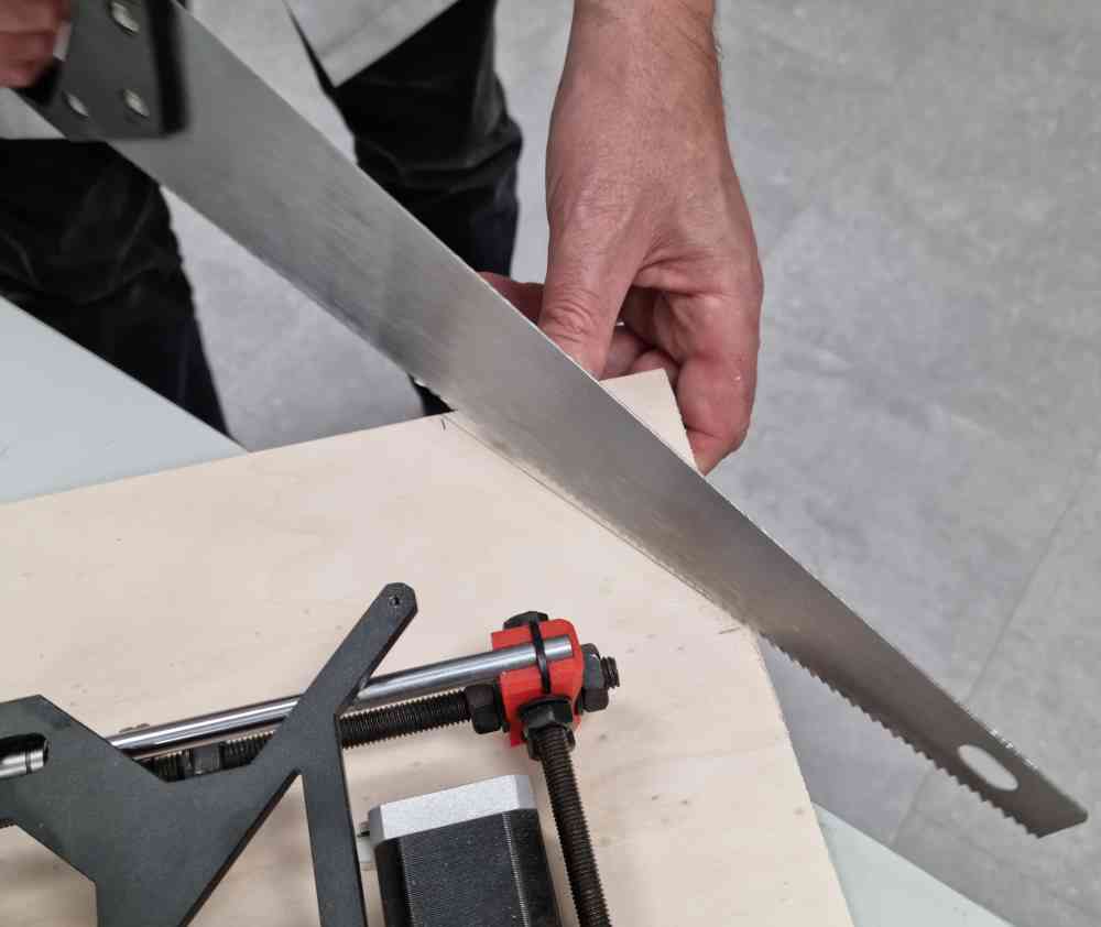
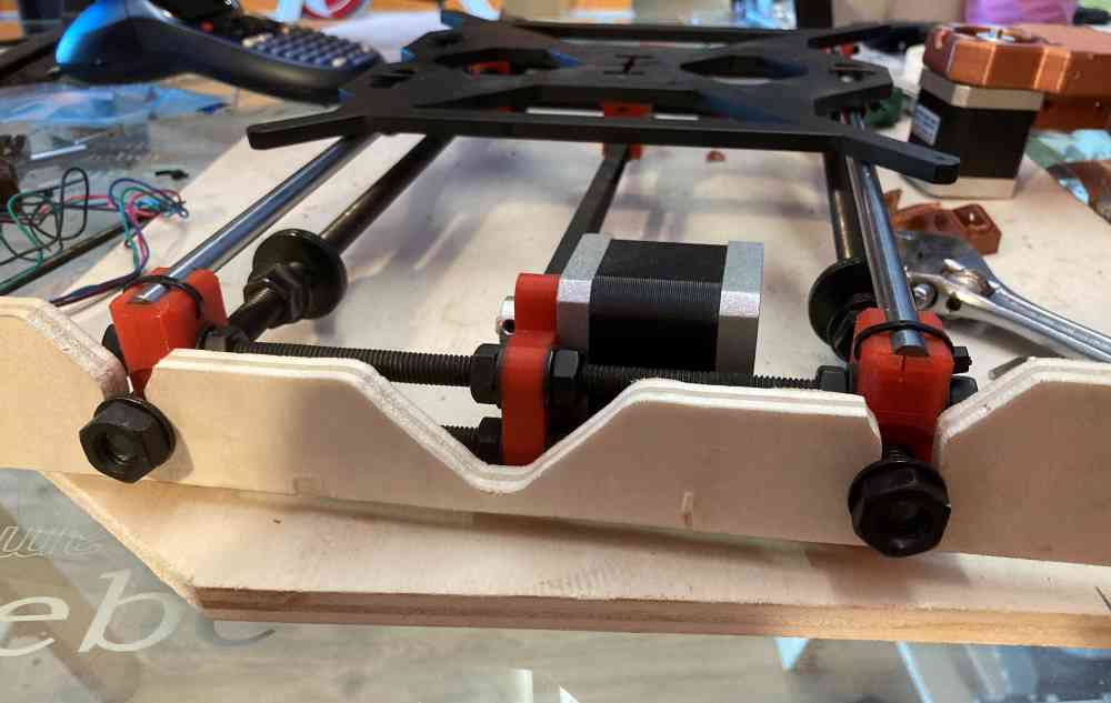
First, we sawed chamfers to the wood base of our Solaser that will later be fixed to the Y-axis movement system and to our adjustable tilt angle system.
 plywood base for the Y-axis.
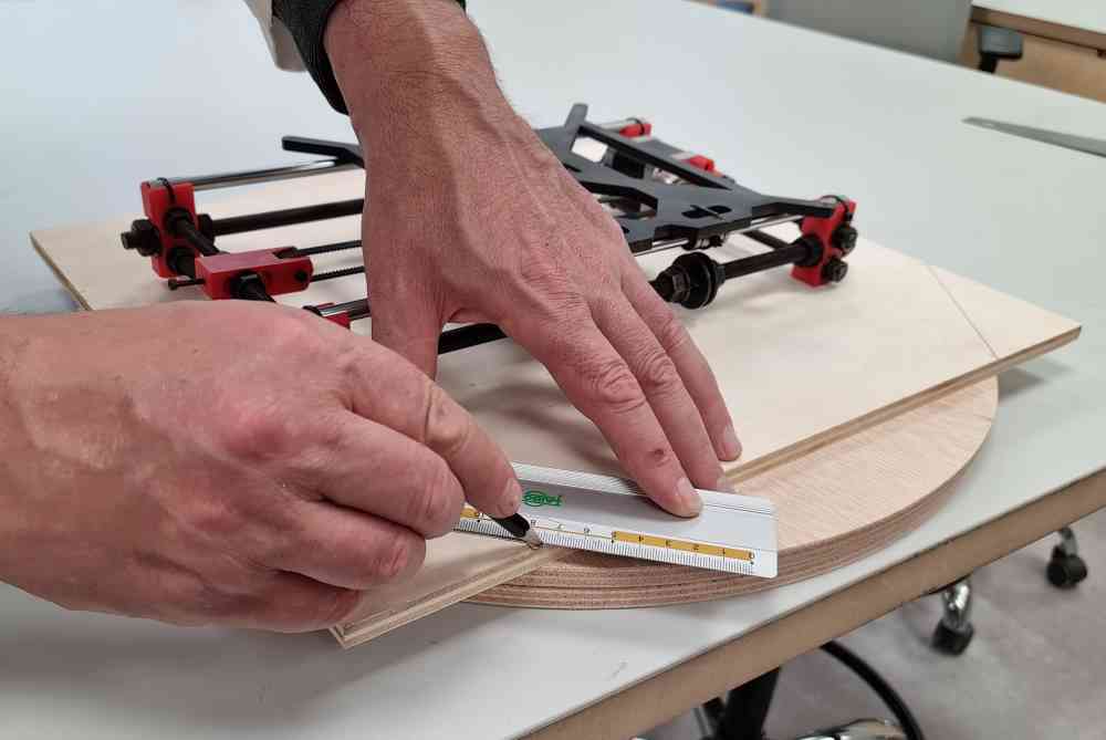
After, we CNC milled the rotatory base, laser cutted our methacrylate circle and 3D printed the screw that fixes them into place.
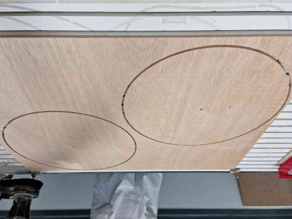 50cm diameter plywood circles.
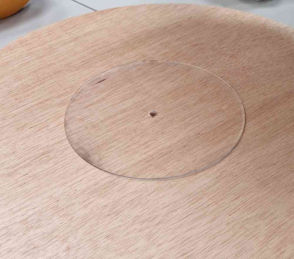 20cm diameter methacrylate circle.
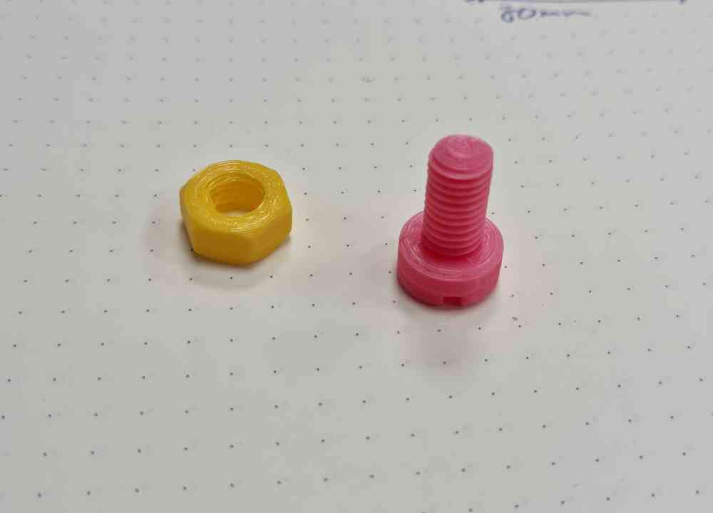 3D printed screw.
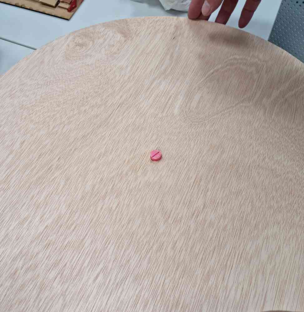 Fixing all into place.
Here you can check some videos of the CNC milling.
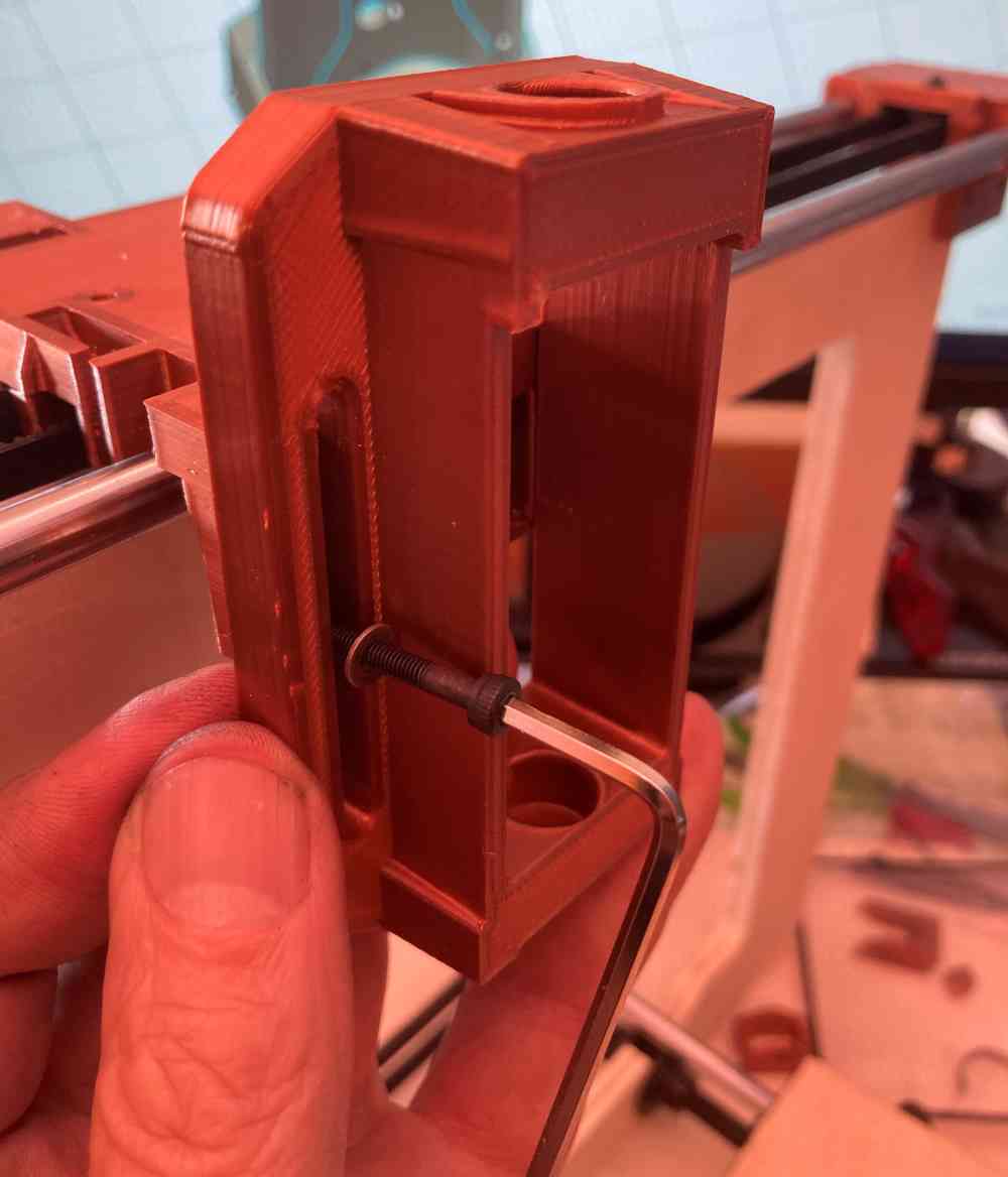
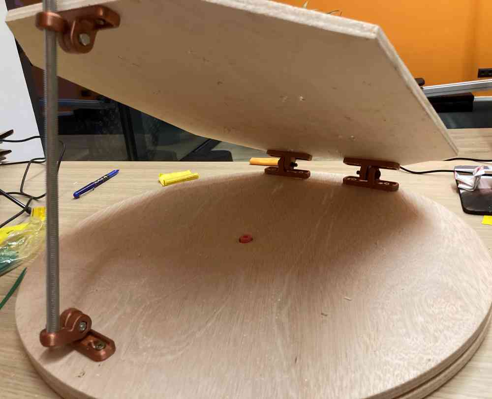
Finally, we 3D printed the pieces needed for our titled angle system that are in charge of giving the inclination we need in our Solaser in order to make it work at any time of the day. You can see in the final image our adjustable tilt angle system assembled.
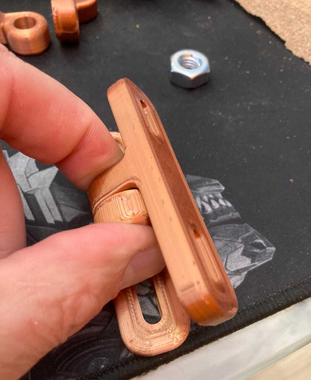
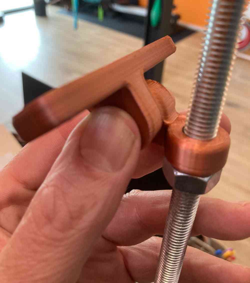
 Home made adjustable tilted angle system.
Here´s the link to download the 2 axis rotation wall mount .stl file from internet used for our adjustable tilted angle system.
DOWNLOAD FILES: Solaser CNC Frame design .dxf, and Rotatory base 3D screw.
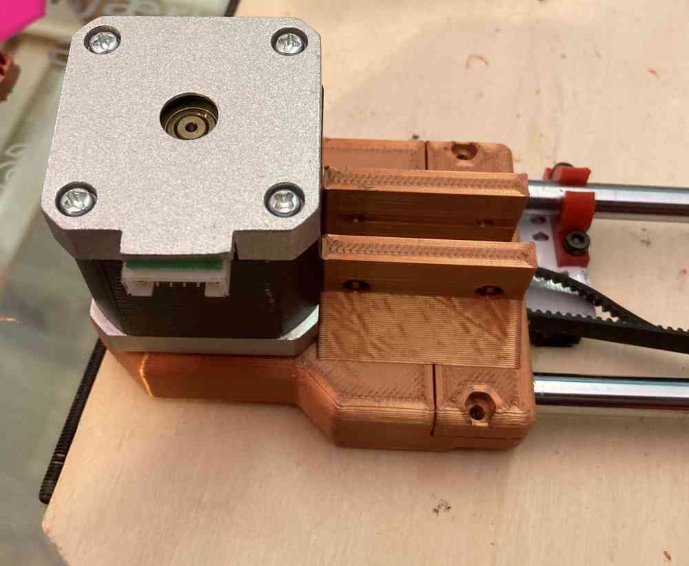
3. RECYCLING PARTS OF THE PRUSA FOR X AND Y AXIS MOVEMENTS
The final part, in order to have all the components ready, is to recycle the motors, belts and steppers from the old prusa, because our goal is to be able to program and move our Solaser with modsCE!
We proceed to dismount all the parts needed, so we can use them later in our machine. As you can see in the images below, we had to take our time to dismount completely the old prusa, selecting the pieces we are going to use. Specially the Y-axis base, that later will need a modification to fit properly in our Solaser.
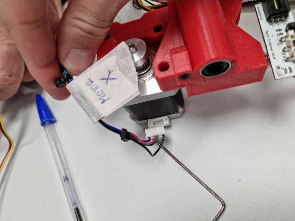 dissasembling X-axis motor and stepper
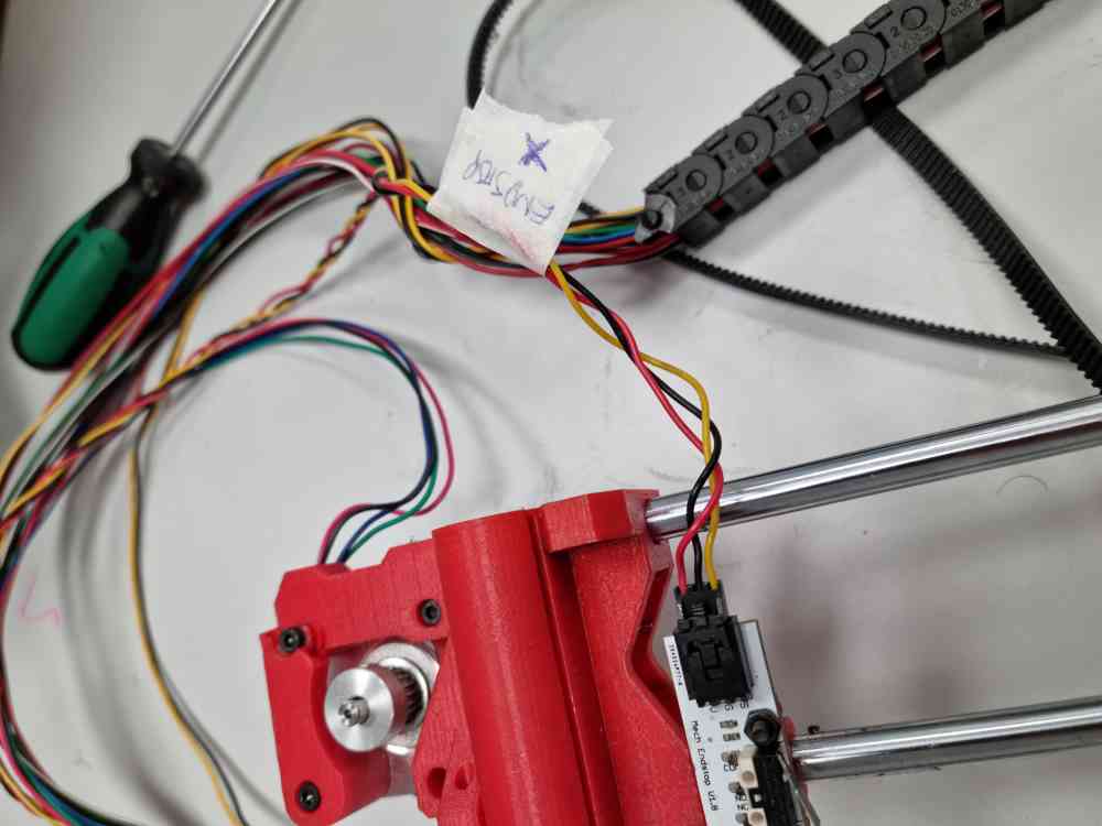
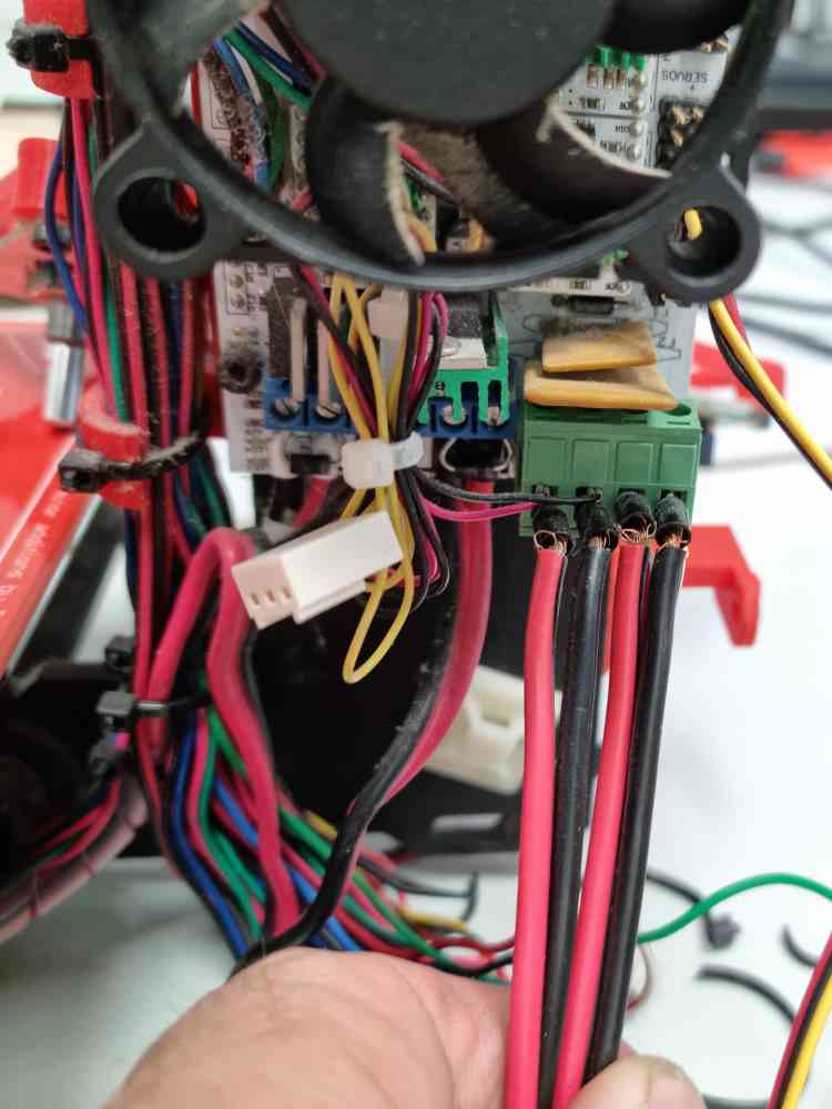
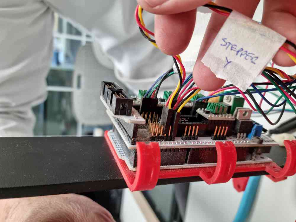 dissasembling Y-axis stepper cables
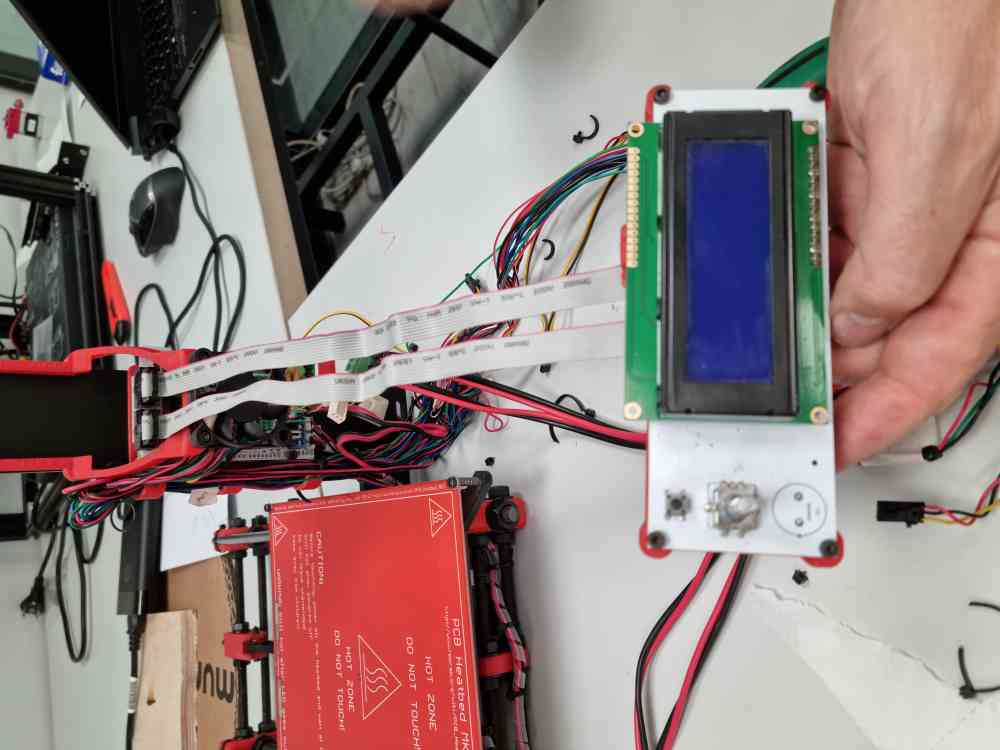 Recycling LCD
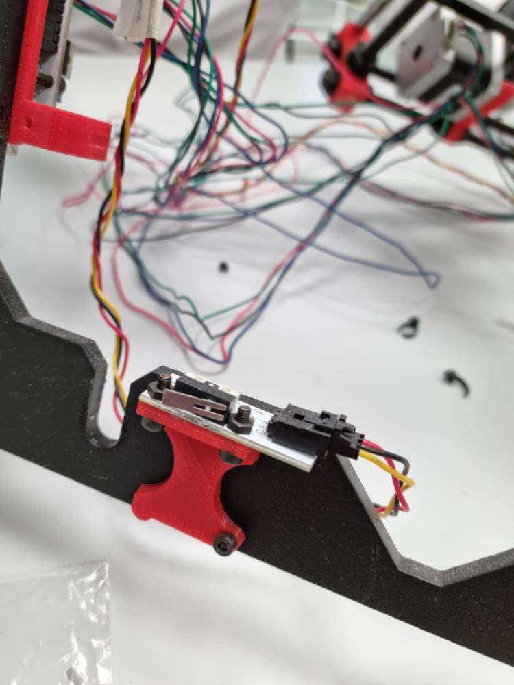 dissasembling Y-axis components
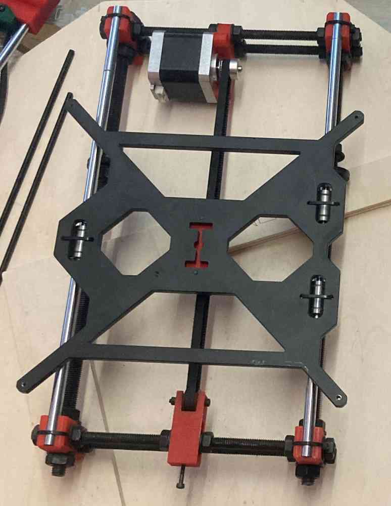
 Before cable removing
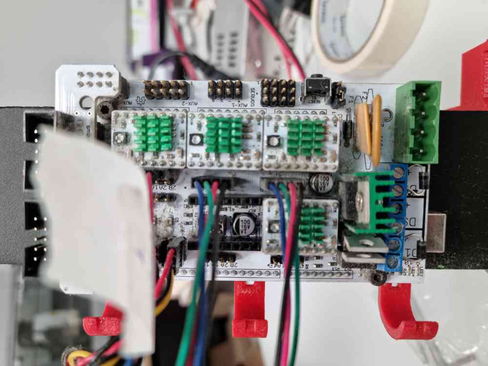 After cable removing
Finally we have nearly all the components needed to start making our Solaser, but we still have time to customize our machine.
4. CUSTOMIZING OUR SOLASER
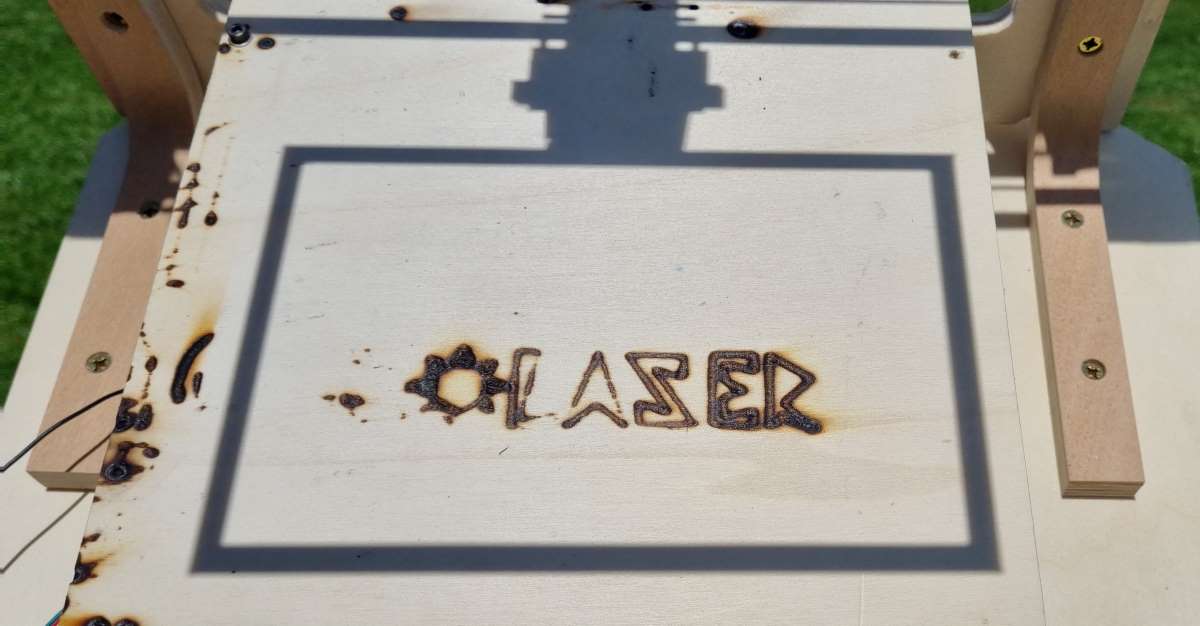
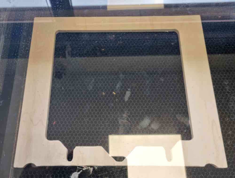
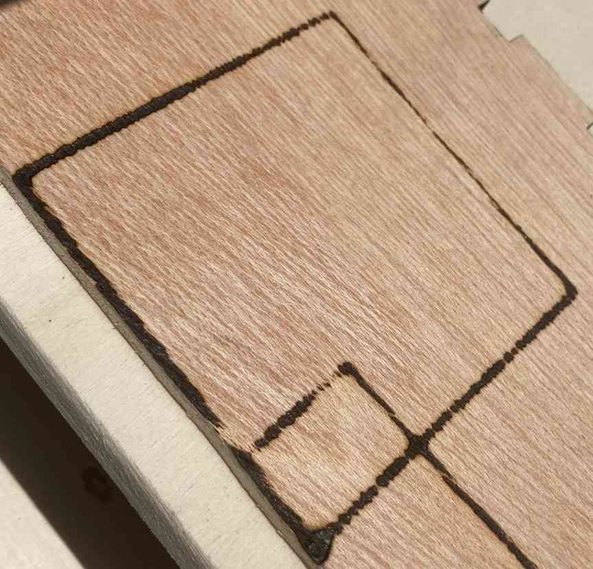
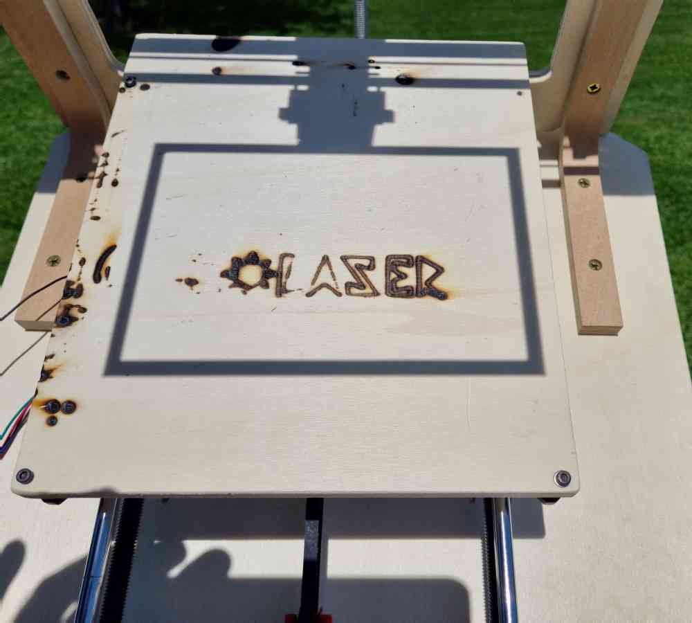
During the days we were able to be in our Fablab, we made the most of the time we had. So we did a couple of things to customize our machine (You never know if you´re going to have time to do this again!). We engraved the frame and a bed cover with our machine´s name. And we also made a 3D printed letters to add into the machine when finished.
Here´s a quick view of what we did:
 Engraving the frame.
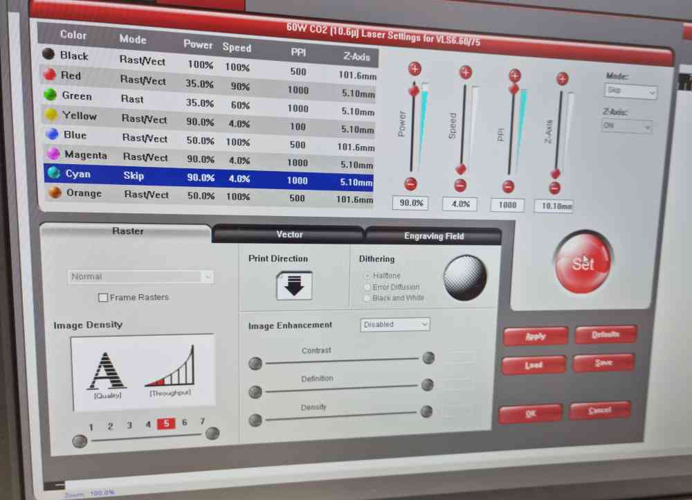 Engraving settings.
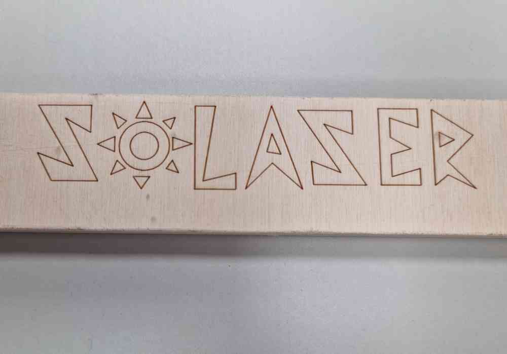 Engraving results
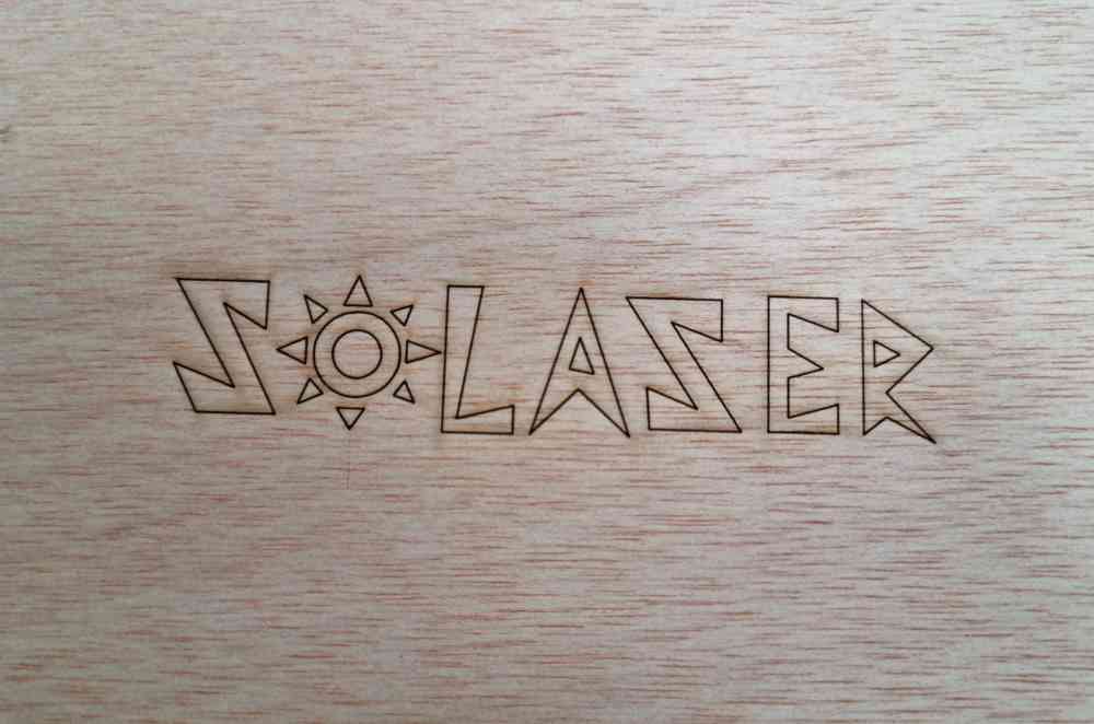 Engraving the Solaser bed.
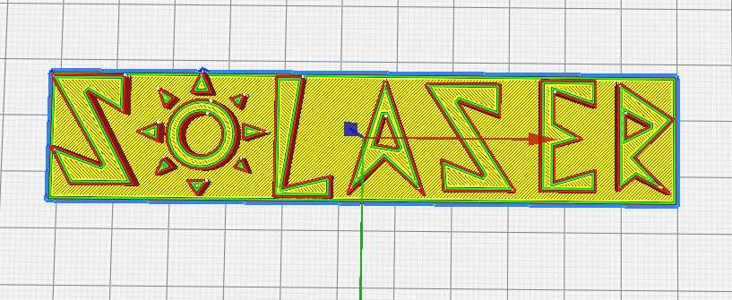 3D printing.
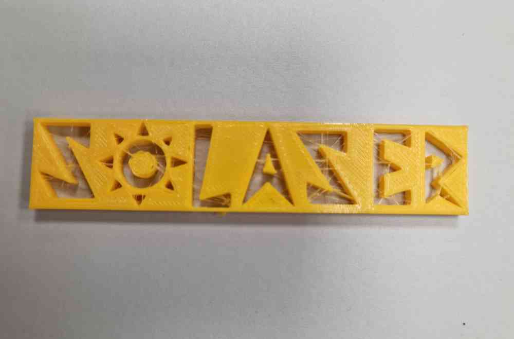
Here you can check some videos of the laser engraving.
DOWNLOAD FILES: Solaser laser .dxf, and Solaser 3D printing letter .obj.
BUILDING IT AT HOME
Now that we´ve got all the parts ready, it´s time to build our machine, but as we commented before, we have to do it at home. In our case, Jon has a small workshop at home, with a fantastic artillery genius 3D printer ready to use, and as you will see later we used it.. a lot!
In order to explain the steps made, we followed the same order that the pieces made, first the frame with the X-axis 3D printer pieces, second, the plywood base with the Y-axis pieces re-used from the old prusa, and fixed to that the adjustable tilt angle system and the rotatory base. And this is the order we´ll show you how we asssembled our Solaser:
1. MOUNTING THE FRAME + THE X-AXIS COMPONENTS
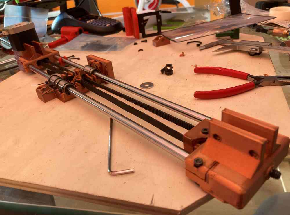
Assembling the X-axis components:
 assembling the X-axis components
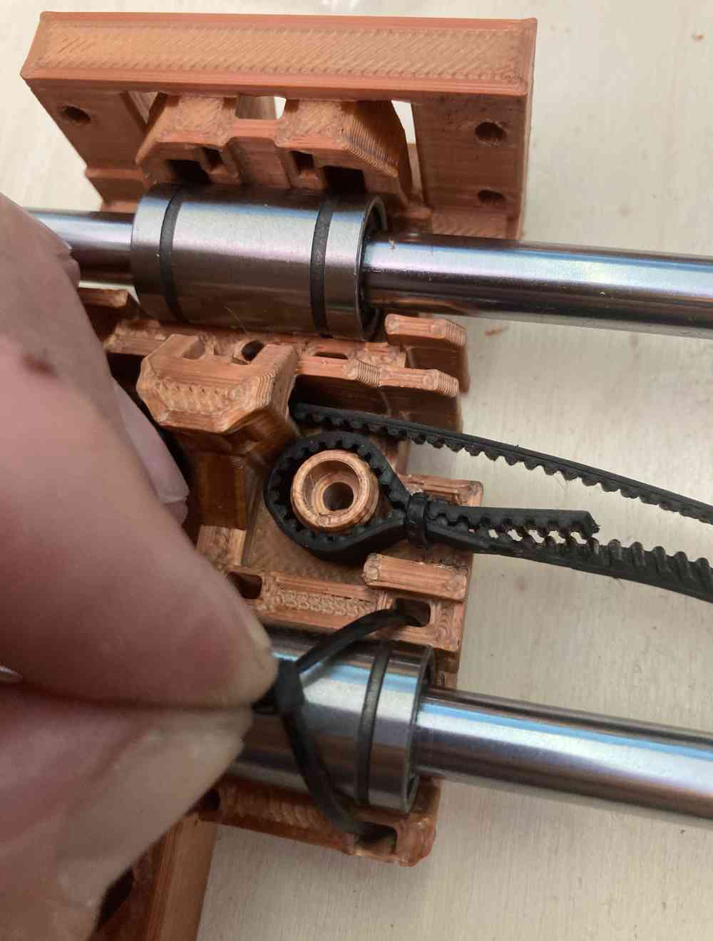
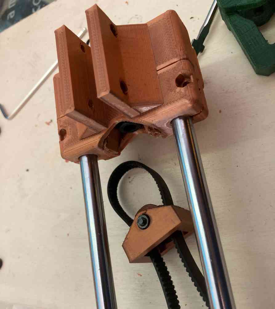
Mounting the X-axis components on the frame:
 mounting the X-axis on the frame
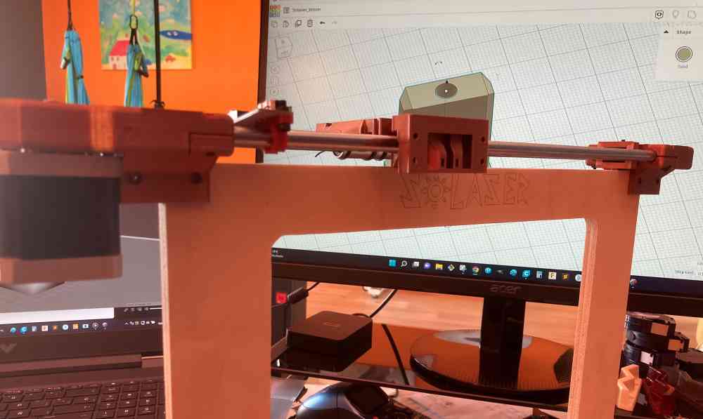
Before and after frame assembling:
 Before
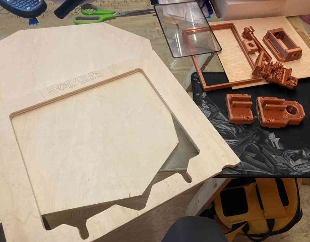
 After
AfterUp above you can check the assembling process for the frame and the X-axis components. The hardest part was to assemble the 3D printed parts with the recycled rods and belts from the old prusa, taking care not breaking the 3D printed pieces when tightening the screws. As you´ll see later in what went wrong, we had to print again a couple of pieces, changing the infill to nearly 100%. But, apart from that, we assembled this first part without much trouble. Now it´s time to go for the second step:
2. MOUNTING THE PLYWOOD BASE + THE Y-AXIS COMPONENTS
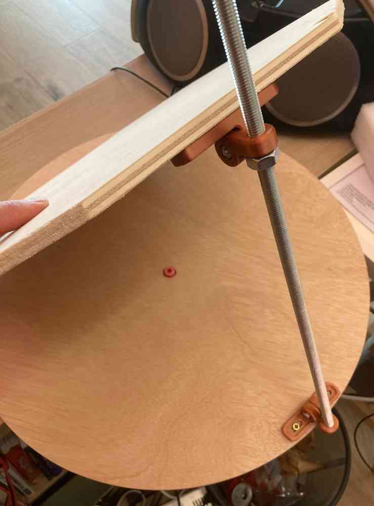
Assembling the Y-axis components to the adjustable tilt angle system and the rotatory base + fixation to the frame (previously mounted):
 Fixing the Y-axis to the frame.
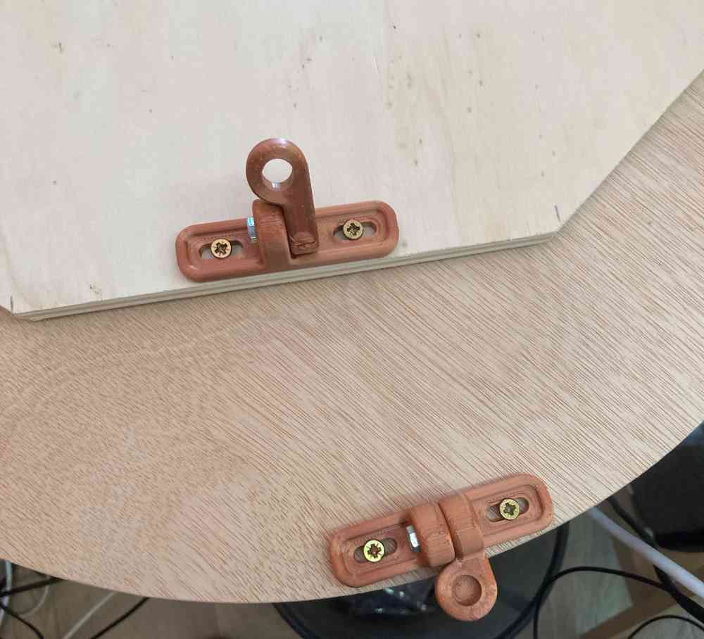 3D printed parts for our adjustable tilt angle.
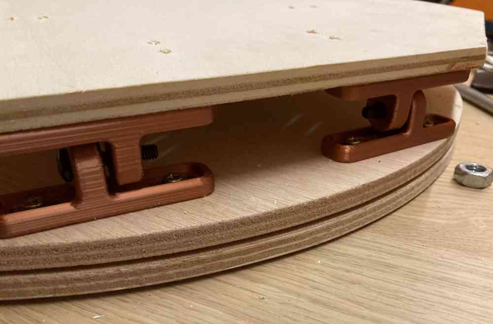
 Adjustable tilt angle + rotatory base.
Y-axis final assembling to the frame + tilt angle base:
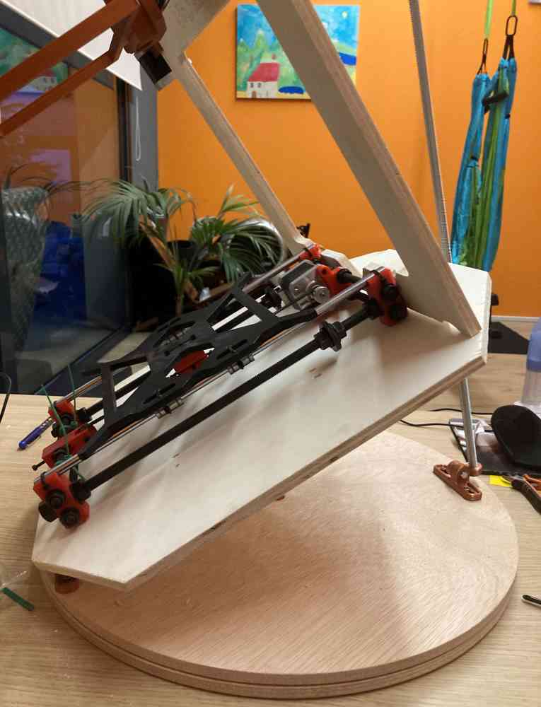 Frame + base assembled.
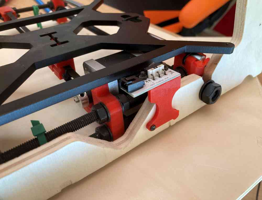 Y-stepper.
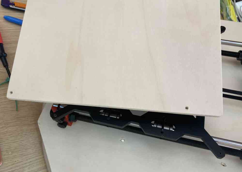 Adding the 10mm plywood bed.
During the assembly of this second part, we had to print several hinges, until we got the ideal one, and also had to re-design how we mounted the frame with the Y-axis, in order to let the lens cover the whole of the machine´s bed, as you can also check later in what went wrong, and what changes did we have to make.
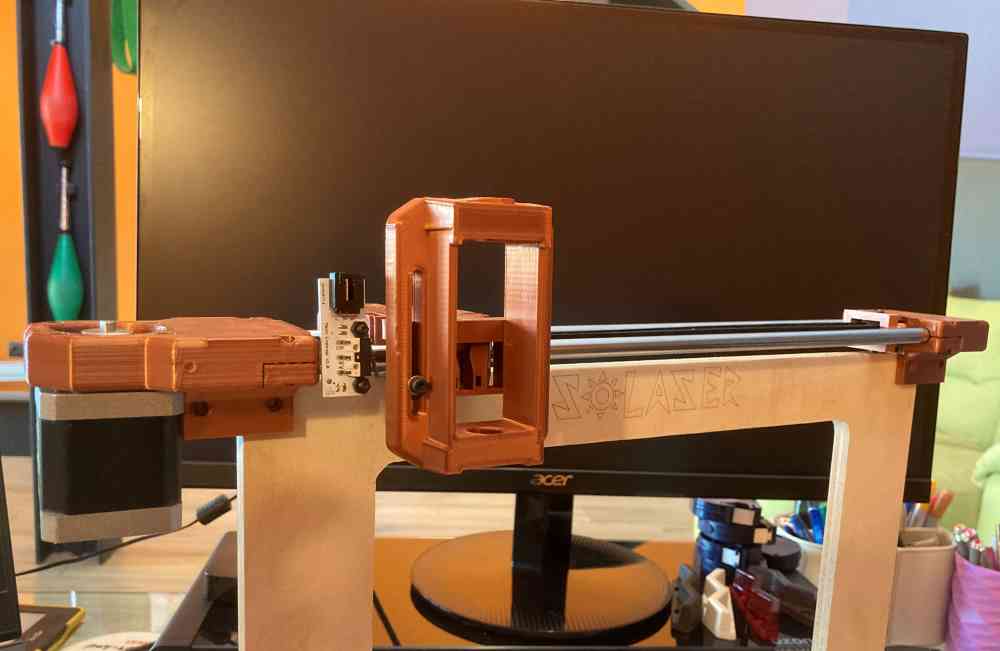
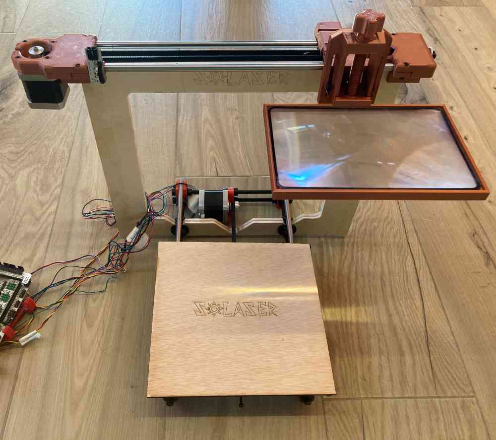
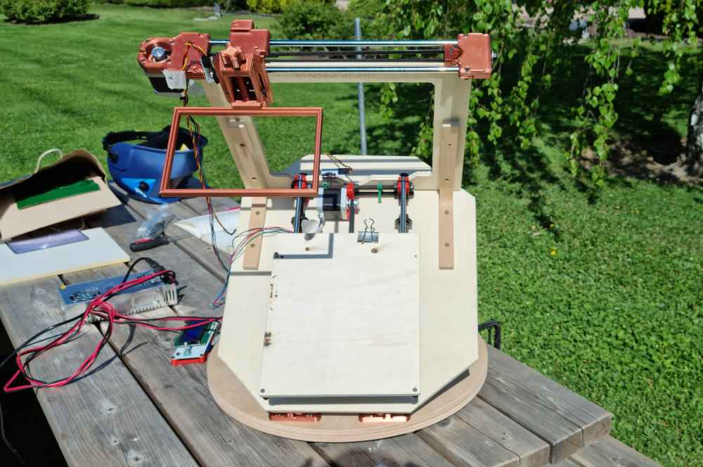
And FINALLY we have our Solaser completely assembled..!
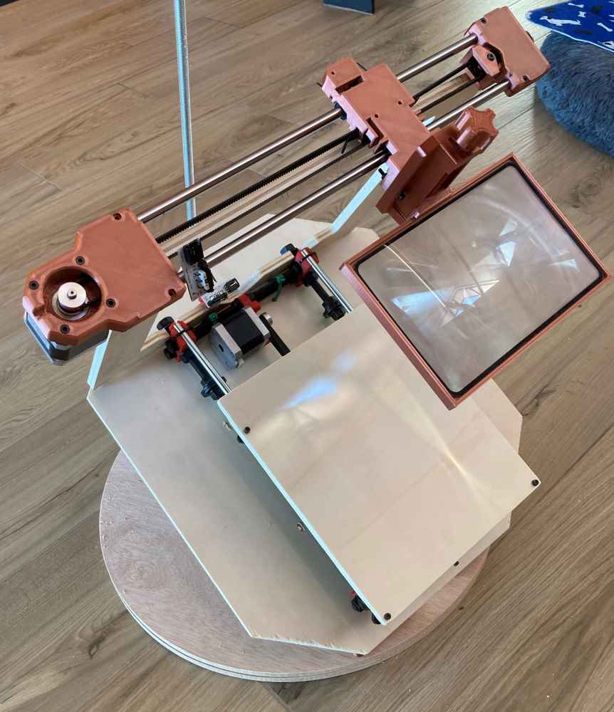 Solaser.
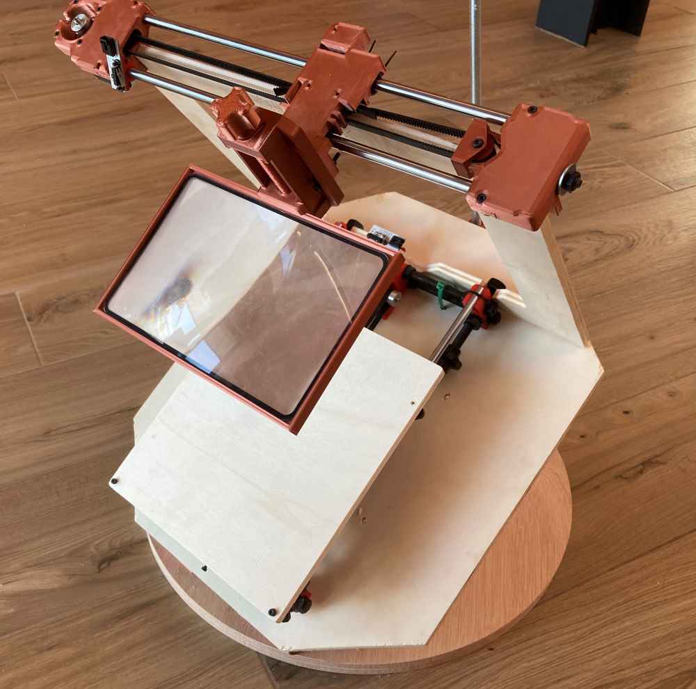
MECHANICAL MOVEMENT
Now that our Solaser is assembled, it´s time to see if it´s capable of moving mechanically in a first spiral.
As we can see in the next videos it moves with full range of motion, but a little bit stiff due to the friction of the motors and belts. But we asume that it will move much more smoothly when we automate it.
As we can see, the Solaser works pretty well. When we move it manually, we can see it "burns" very quickly the tested material, and probably it will do it better when we get our Solaser running automated, as the speed will be constant and therefore more precise.
AUTOMATED MOVEMENT
As our goal is to connect and move our Solaser with modsCE, we reviewed tutorials about Making machines move with mods CE, as part of a master class in the Global Open Time, due to the fact that the only experience that we have with modsCE is to move our Roland Modela MDX-40 in the electronics production assignment.
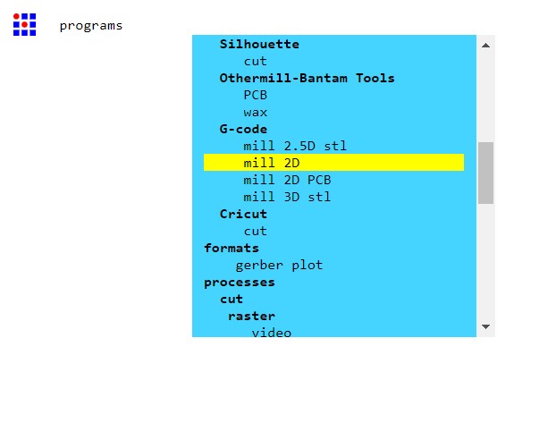
To test possibilities regarding modsCE, we did as first test g-code, a simple square:
| Open modsCE program -> G-code mill 2D. |
| Select SVG or PNG file to read: a simple square. |
| Edit mill raster 2D options: Edit code to our Solaser needs. That means to leave only offset number (value=1), direction and path order (foward). |
| Edit path to G-code options: Edit code to our needs. Cut speed=10mm/s, coolant=off, format=mm and rate units=minute. |
| Once both modules are edited: Save program to file -> Solaser 2D. |
| Calculate and review the toolpath. |
| Change file extension from NC to .gcode. |
| Load it to our Solaser via SD card. (We had some troubles here, but we´ll explain later on). |
 Mods G-code.
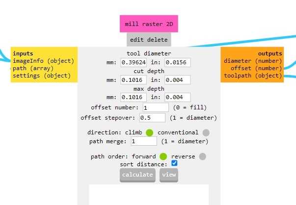 Mill raster 2D.
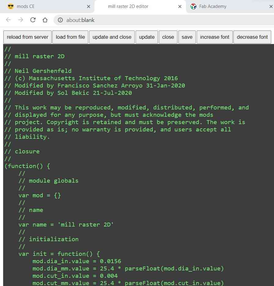 Mill raster 2D edit code.
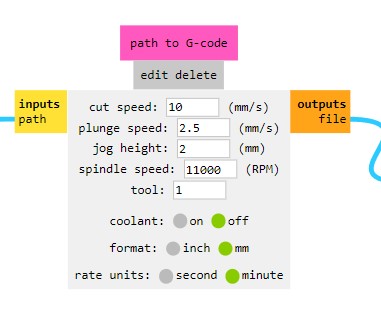 Path to G-code.
After editind the modules, we saved our program file, named Solaser 2D, and here you can see the Solaser automated calibration first and our first test after:
DOWNLOAD modsCE FILE AND GCODE FILE: modsCE_Solaser2D_file., and Square_test_Gcode.
After carrying this first test, we confirm how well it works (we´re completely excited with the results!!) when doing our first code with modsCE. So, it´s time to test with more complex images, testing our Solaser design rules. So here´s how it went:
First of all we generated the final Gcodes in our Solaser 2D modsCE file. That, even do it needs improvement, it works nearly always!
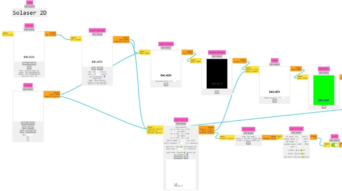 Solaser2D modsCE file.
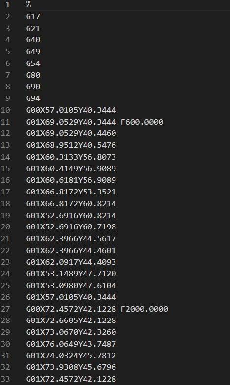 Gcode.
Here you can see the final toolpaths for all the test we did:
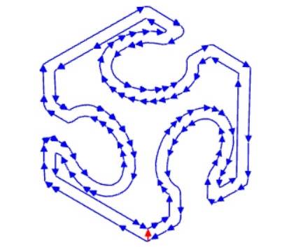 Toolpaths.
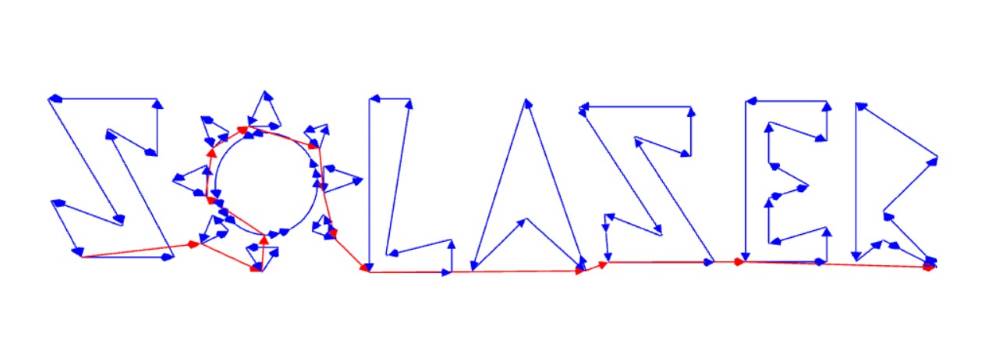
As you can see we used .svg files to generate our codes, and when reviewing the toolpaths, and after the first test-runs, we had to change the speed regardind the "burning" process (600mm/min) and the speed when moving from one part of the design to another (2000mm/min) to avoid burning excesively the material tested.
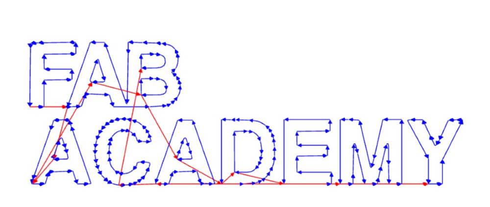
FABACADEMY LOGO TEST
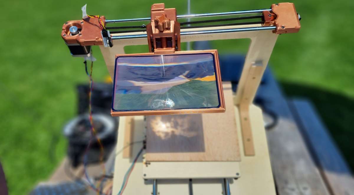
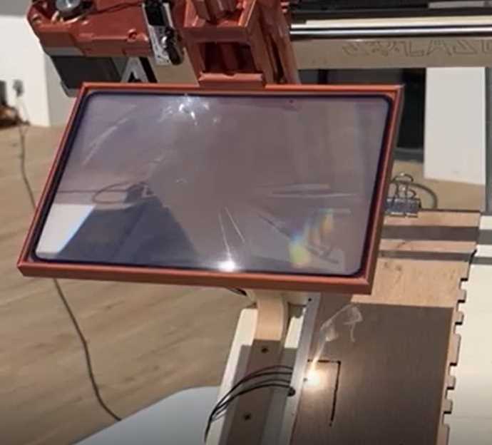
 Preparing the Solaser.
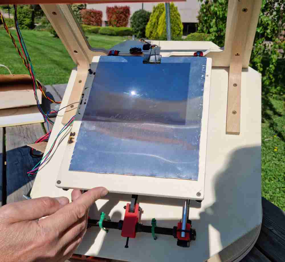 Adjusting the focus lens height.
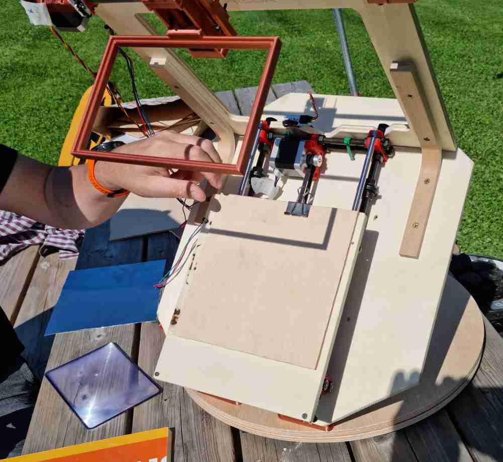 Preparing the material.
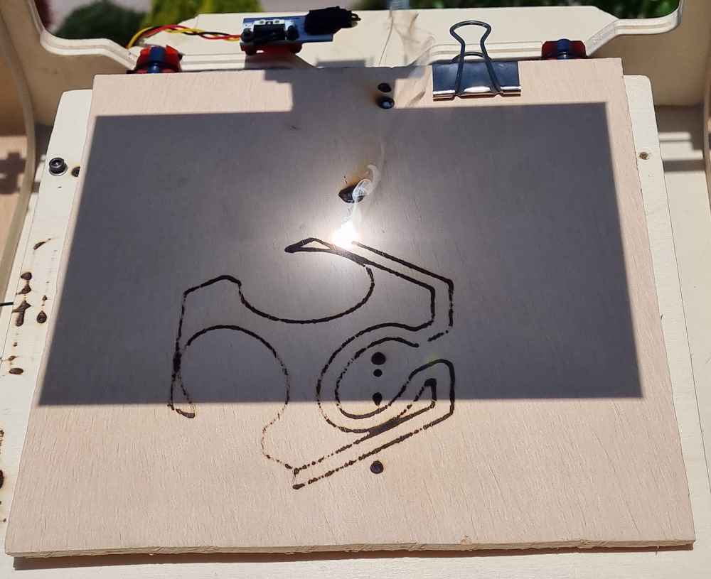 Fabacademy logo test.
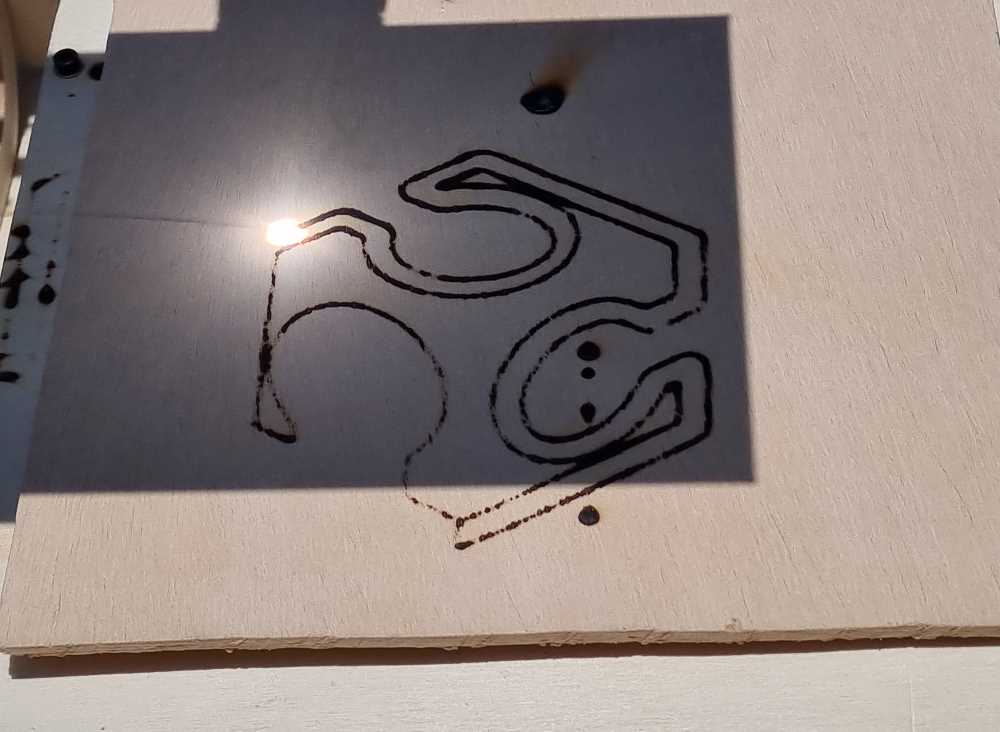
As you can see here, we tested different materials (plywood and chipwood), and both of them "burned" well at 10mm/s:
 Solaser in plywood.
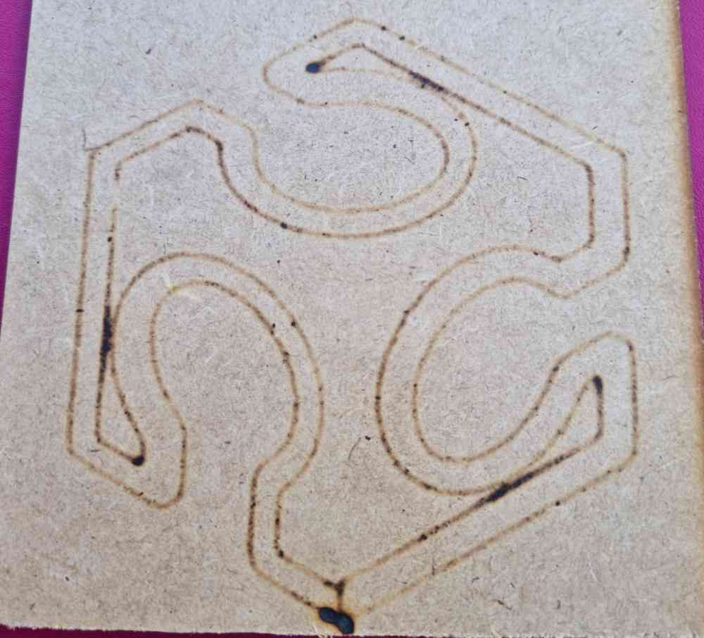 Solaser in chipwood.
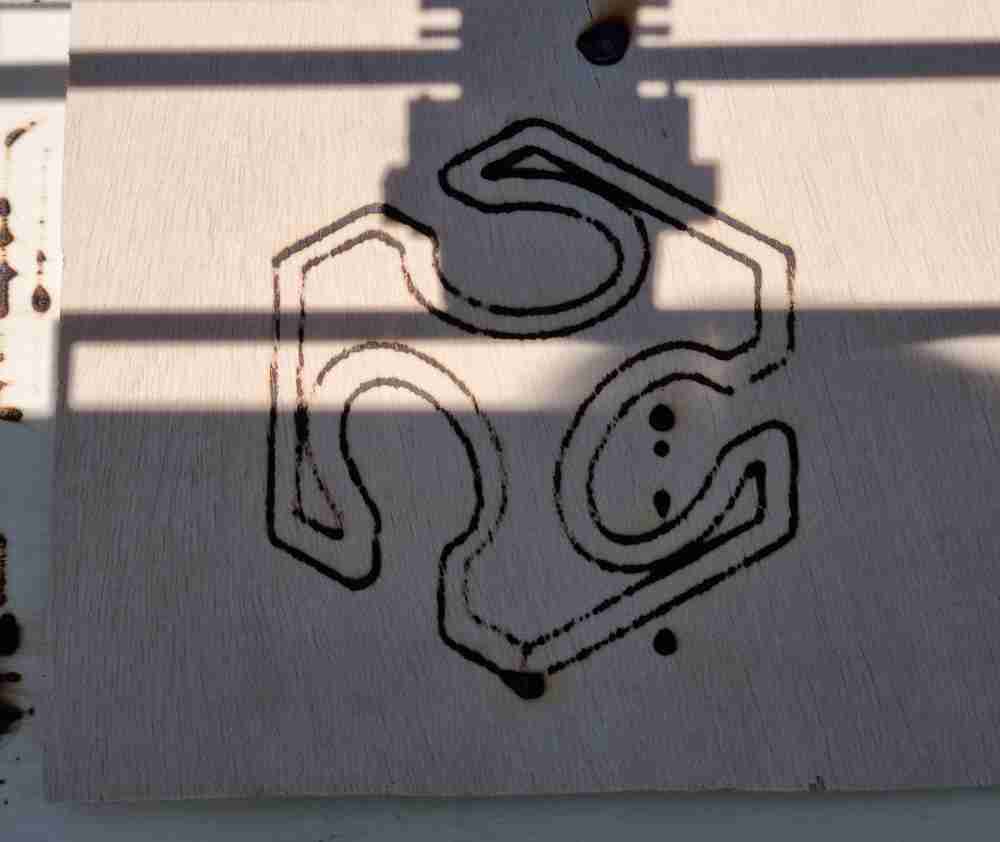
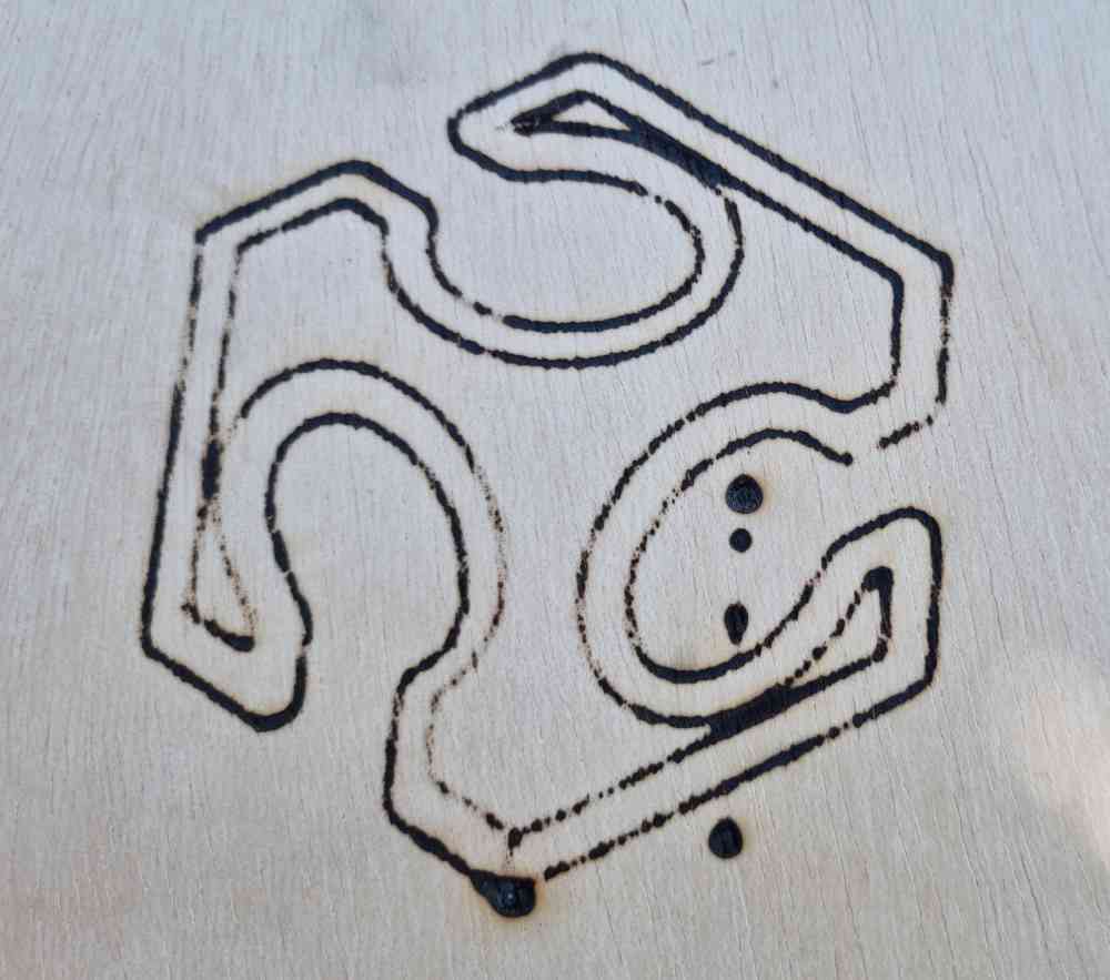
SOLAZER LOGO TEST AND FABACADEMY LETTERS
 Solaser logo.
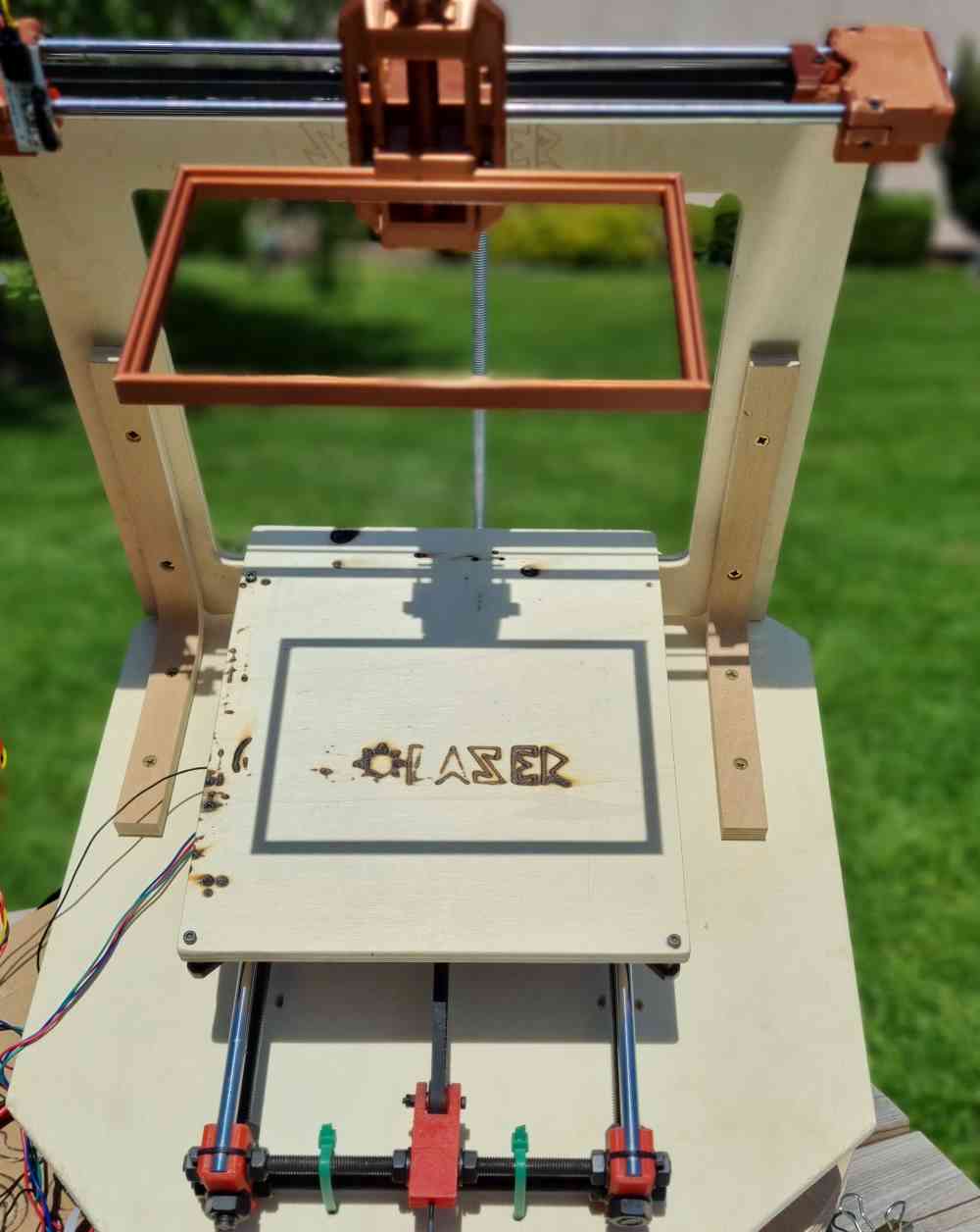 .
.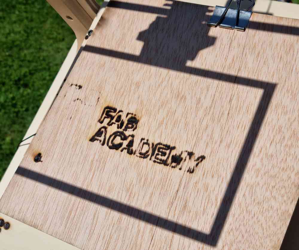 Fabacademy letters test.
Here you can check the video (at 2x speed) of the Solazer logo engraving in the bed of the machine, also at 10mm/s:
Here you can check the video (at 2x speed) of the Fabacademy logo letters test, also at 10mm/s:
DOWNLOAD SVG AND GCODE FILES: Fabacademylogo.svg, and and Fablogo_Gcode.
DOWNLOAD SVG AND GCODE FILES:Fabacademyletters.svg, and Fabacademy_test_Gcode.
DOWNLOAD SVG AND GCODE FILES:Solazerlogo.svg, and Solaserlogo_Gcode.
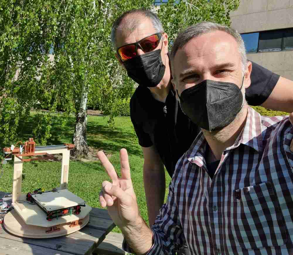
It´s important to take into account, that the sun beam is so bright you have to wear sunglasses to protect your eyes through out the whole process, you have to be very careful and aware of having the lens lid on when not using it, because if not, there´s a risk of burning the material or the Solaser!. And finally, smoke will come out from burning the material, so handle the solaser in open spaces.
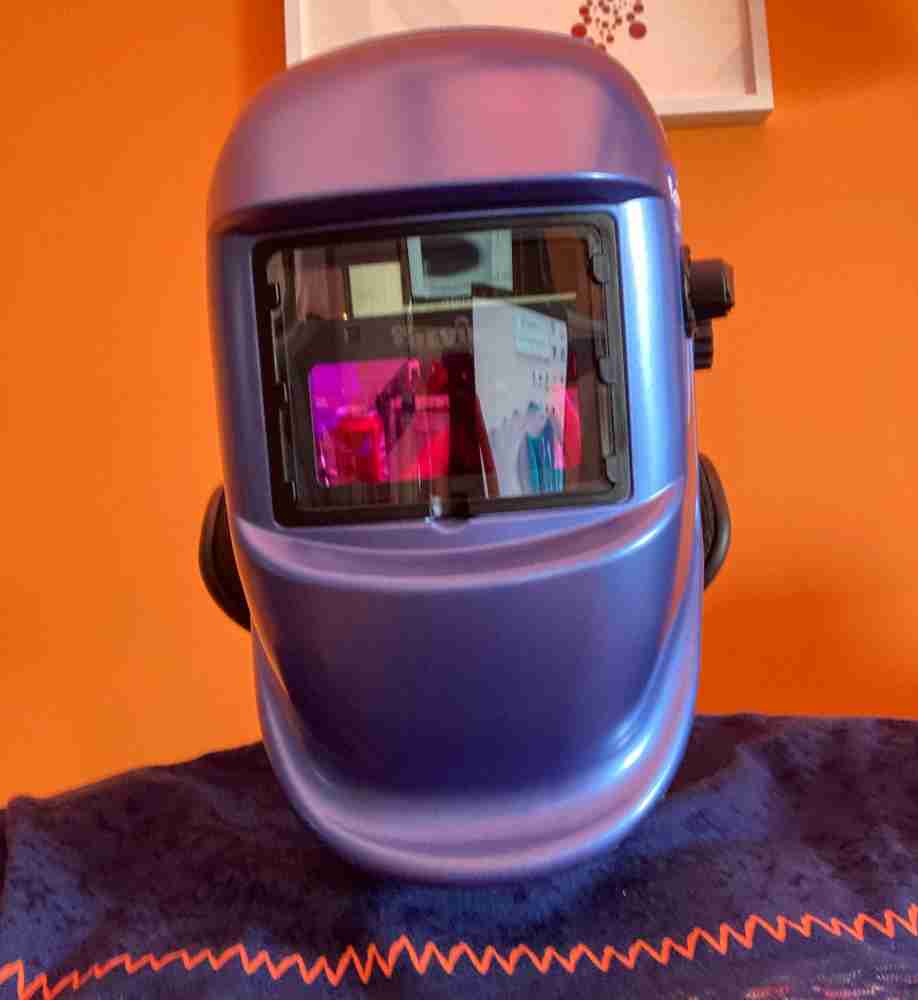 Eye protection.
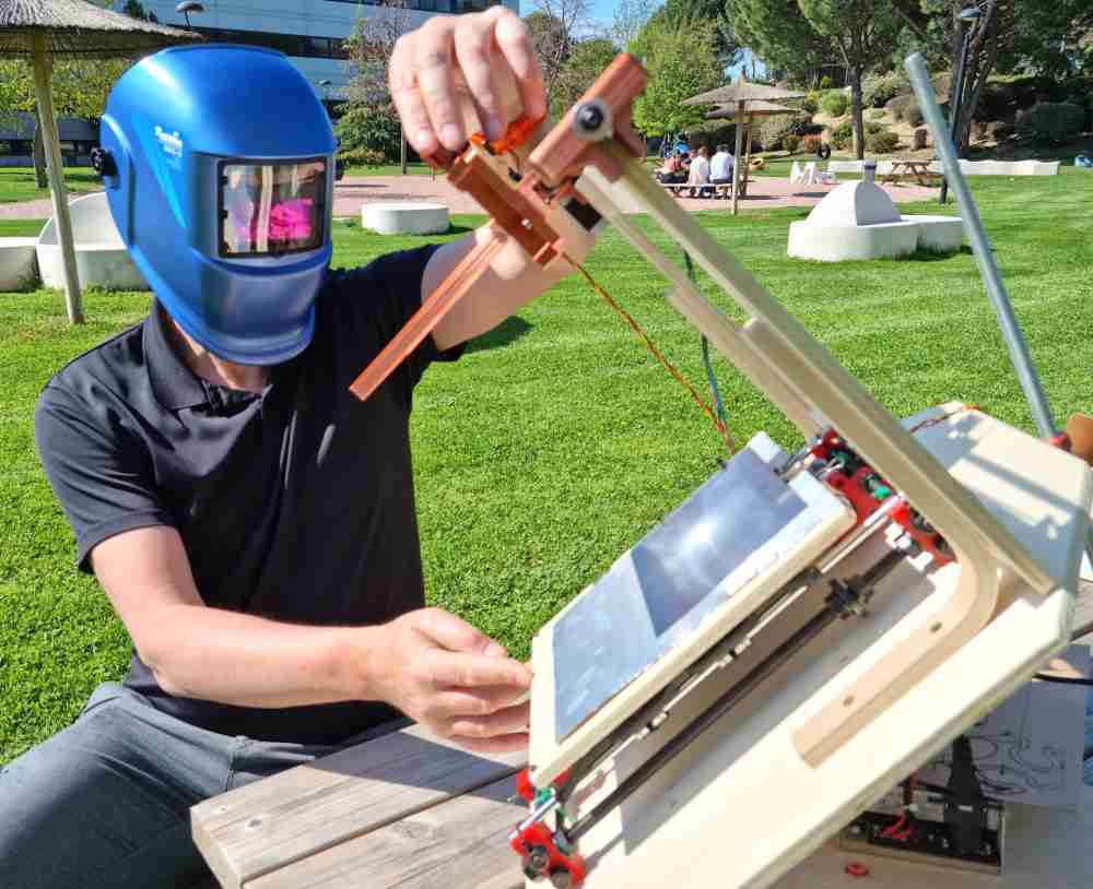
 Use it in open spaces.
WHAT WENT WRONG TROUGH THE PROCESS
As it could not be otherwise, there were mistakes, errors, and improvements during the development of our Solaser. Here´s a list (in cronological order) of them:
| ERRORS AND IMPROVEMENTS | How we dealed with them |
|---|---|
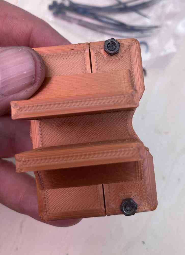
| 3D printing errors | Our first improvements were regarding 3D printed parts of the X-axis, we had some printing errors, we had to redo and modify some of the parts in order to make them fit with the other components. |
| Changing infill settings in 3D printing | We also had to change the infill from the initial 20% to a full 100% in order to be able to withstand the forces to which they are exposed. |
| Adjust x-axis belt tightener | We had a screw touching the x-axis belt movement, so we had to re-adjust the belt tightener by using a different screw. |
| Lack of stability of the frame | Once we mounted the frame, we found out that it wobbled a bit, so we reinforced it with a couple of wooden brakets. |
| Changing Y-axis design | Once we had our Solaser completely assembled and did our first test, we found out that bed didn´t move with enough amplitude in the y-axis, so we had to do a little modification to solve this issue (as you can see in previous image). |
| Frame dimension | We also find out that we made our frame a bit too small, and we could only fix an x-axis component with one screw.. To take into account if we biuld a second version! |
| Solasering methacrylate | We also tested our machine with methacrylate material, but even do we tested at differents speeds, we were´nt able to "burn it", probably due to the reflection of the sun beam in the material. |
| ModsCE Gcode programming | Even do our Gcode, from modsCE, works, sometimes it gives an unspecific error. It stops and dissables steppers. Then we just have to restart the machine and it works. |
| Cardboard cut test fail | Whe tried to "cut" a 6mm cardboard, but all we achieved was burning it. So, lesson learnt!. |
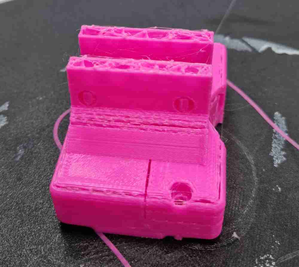 3D printing errors.
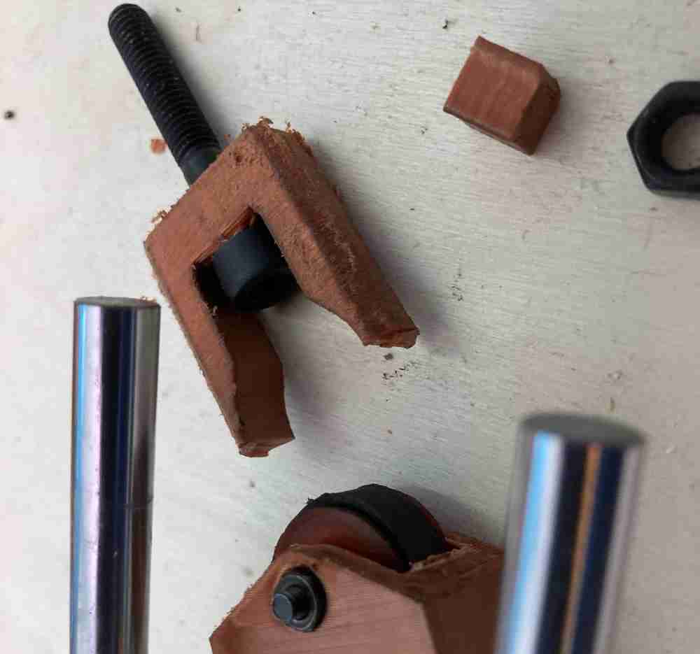 Changing infill to 100%.
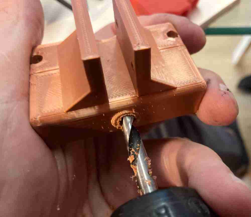 Modifying 3D printed parts.
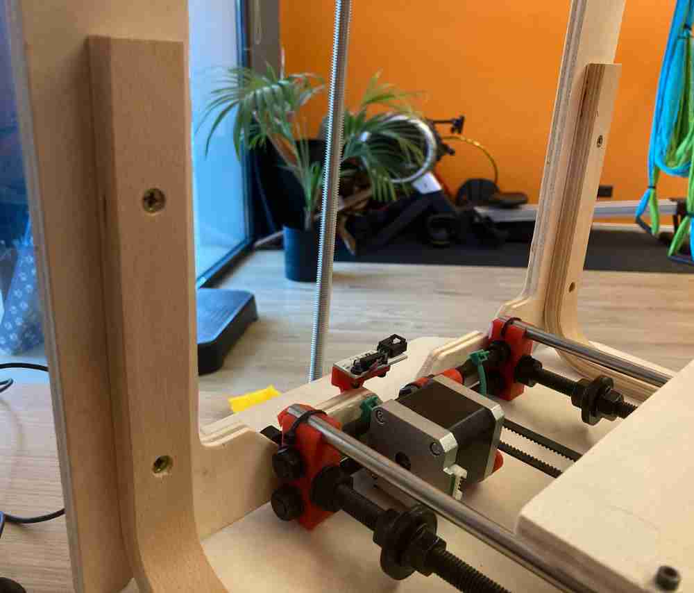 Adding wooden brakets for stability.
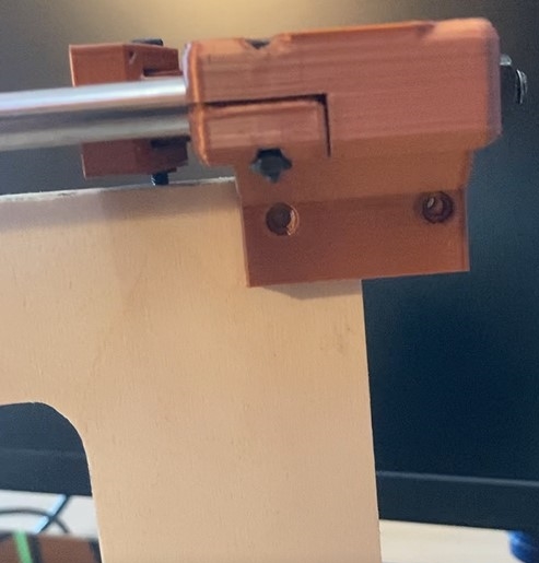 Frame dimension error.
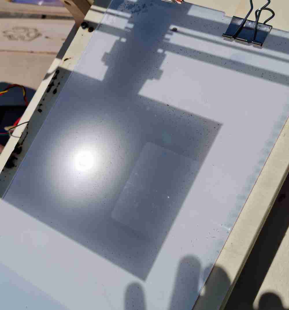 Testing in methacrylate.
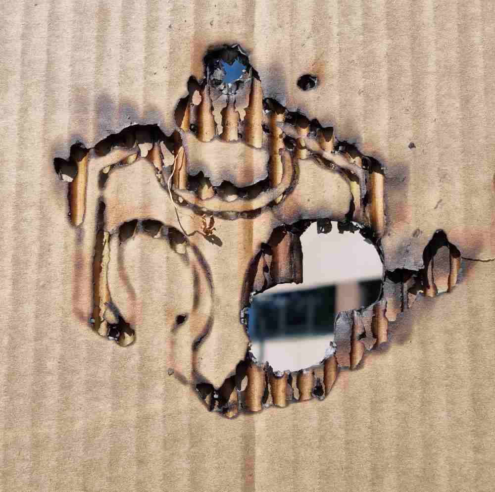 Cardboard test fail.
Finally, we´re enthusiastic with what we´ve achieved, with our Solaser. We planned well our time management, and we have fully committed to it, and our final machine definitely exceeds our firsts spiral goals. But, as every week in Fabacademy, there´s things that we would like to improve or develop more, such as a more precise modsCE GCode, or create our own pcb boards to move the axis motors. Surely in the near future we´ll do some improvements, but for now, we´ve run out of time.
GO TO FabLab UE HOME PAGE.
GO TO Jon Merino´s HOME PAGE.
GO TO Pedro Chana´s HOME PAGE.

This work is licensed under a Creative Commons Attribution-NonCommercial-ShareAlike 4.0 International License.