03 Week :: COMPUTER CONTROLED CUTTING

We reached the third week and we are already immersed in the great universe of FabAcademy. The many manufacturing possibilities that we are already beginning to sense are starting to trigger ideas and new projects. The weekly assignments take up all our time... and also our dreams! A small preview of the result and then the challenges and the associated work process.
Week Challenges
This week we will be working with laser cutting and vinyl cutting tools. These are the resources reviewed in the Global Session, our weekly assigment, and associated tutorials (I recommend reading them), as they are very helpful.
FabAcademy Challenges:
- Group assignment:
- Characterize your lasercutter's focus, power, speed, rate, kerf, and joint clearance
- Document your work to the group work page and reflect on your individual page what you learned
- Individual assignments
- Design, lasercut, and document a parametric press-fit construction kit, which can be assembled in multiple ways. Account for the lasercutter kerf.
- Cut something on the vinylcutter.
GROUP ASSIGMENT
For this firs grupal assigment, my fabmates and myself have document the following machines:
- Laser Cutter Machine: see Pedro Chana assignmet.
- Wazer Water Jet Machine: see Jon Merino, assignment.
- Vinilo Cutter Machine: keep reading.
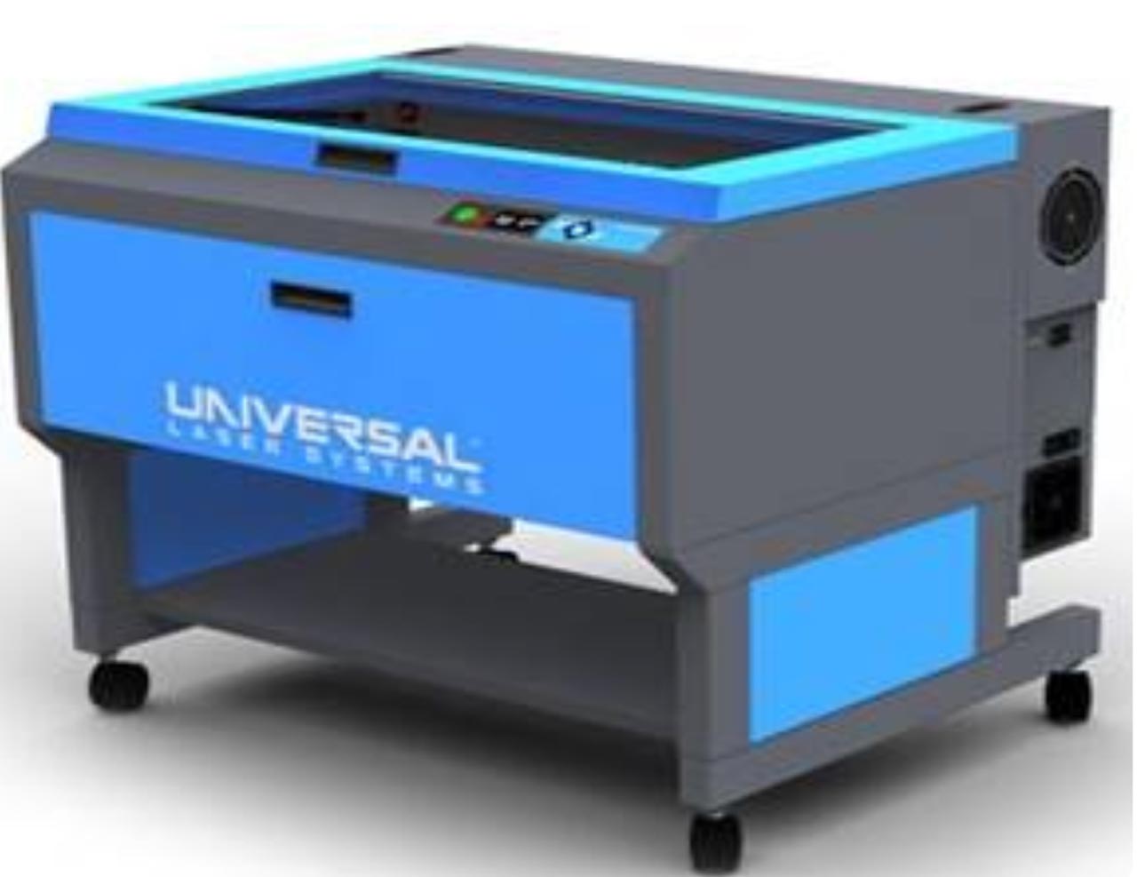
1. LASER CUTTER MACHINE
Together with my colleagues from Fablab UE Madrid, Pedro Chana and Jon Merino, we have to document our laser cutter. We have a VLS 6.60 laser cutter.
Safety Procedures
Our instructor, Alberto, has given us indications about safety with the laser cutter. This device is designed for laser cutting and engraving, and both need to follow some general requirements to ensure that no damage is done:
- Check that the ventilation is on. A properly operational particulate and fume exhaust is mandatory when operating the laser system.
- Turn on with the lid closed. Exposure to the laser beam can cause severe damage.
- Calibrate and add material
- Before using a material for the first time, check the material safety data sheet. Some materials can produce toxic and corrosive fumes.
- Never operate the laser system without constant supervision of the cutting and engraving process.
- Never leave materials in the laser systems after the laser processing has finished.
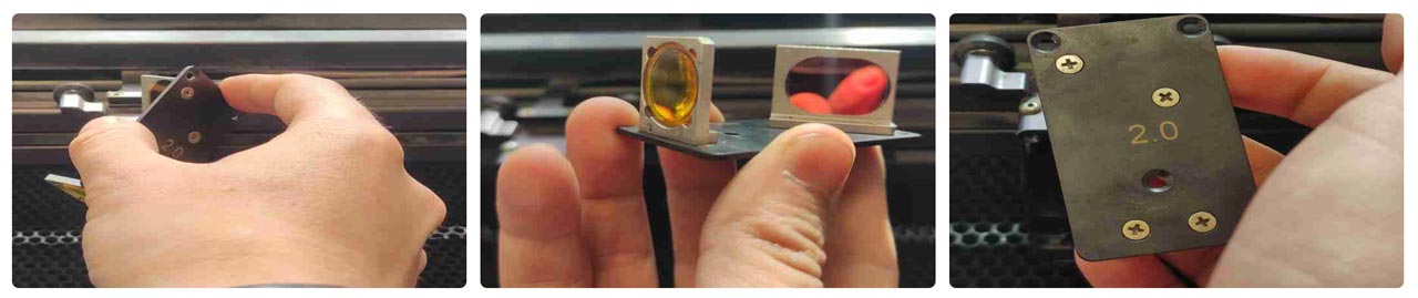
We share some images of the machine head, which we have disassembled to understand its interior. It is important that it is always clean and does not accumulate carbon for the proper functioning of the machine.
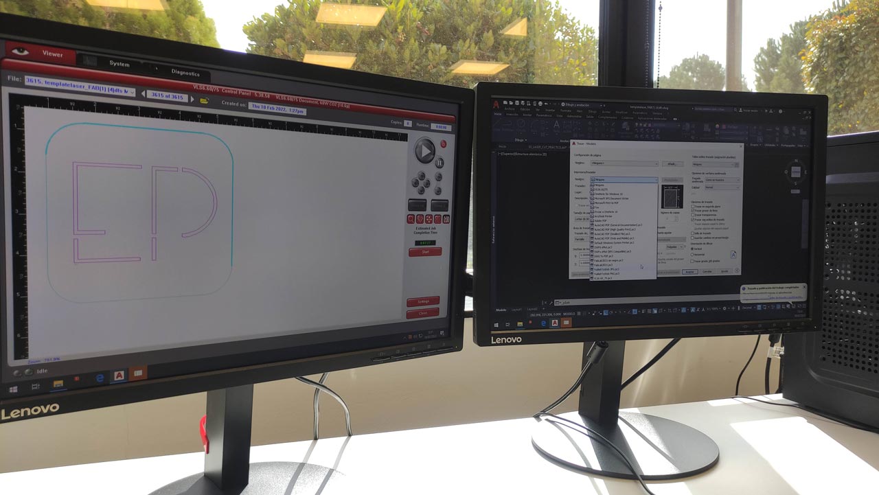
Launching the file to the laser machine
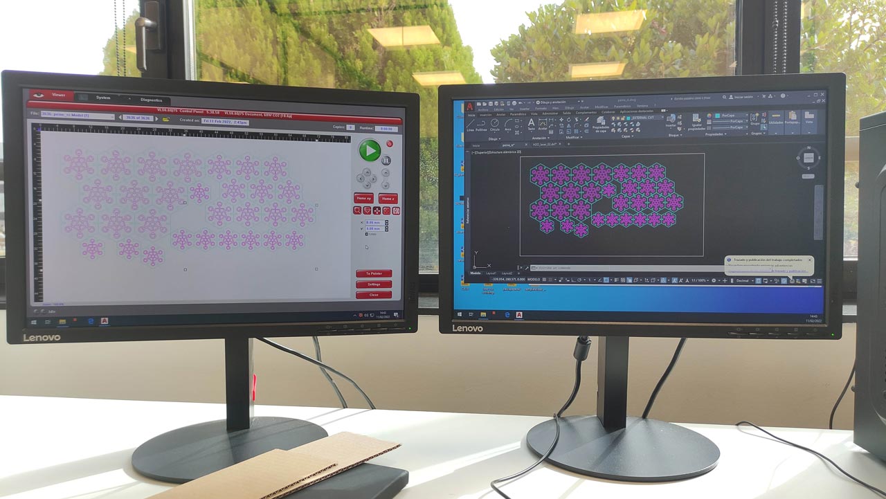
- Once we have all the file prepared in AutoCAD, we perform the following commands: Print /pre-plot /window /select what we want to throw to the laser (it is important to place a point at the 0,0 coordinate of our material) /send to the laser.
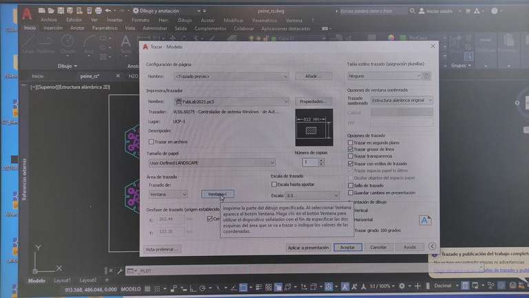
- Once in the laser interface, we load the settings. Look in the settings library, apply and click ok. If we want to make any change in any parameter we choose the layer, set and apply (one by one). Confirm the configuration by pressing ok.
- We send our design to the coordinate 0,0; clicking on the crosshairs and giving the values x=0 y=0; to see the estimated time / click on the clock and it indicates when it will take the cut. We check that our material is on the laser table, that it is fixed to its edges, and that the lid is down.
- If we have checked everything, and it is convenient to do it twice, we press play. If all goes well... enjoy the spectacle of cutting.

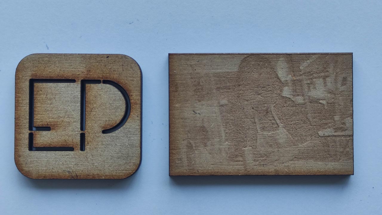
In our group assignment we have made an engraving (raster) and an inner and outer cut.
Library of materials
The FabLab de la UE has a library of material configurations that have been made since its inception. It is very useful as there is usually a material with the thickness and characteristics of the one you are going to work with. However, it is important to always do a test run, e.g. a circle or similar, to check power and speed.
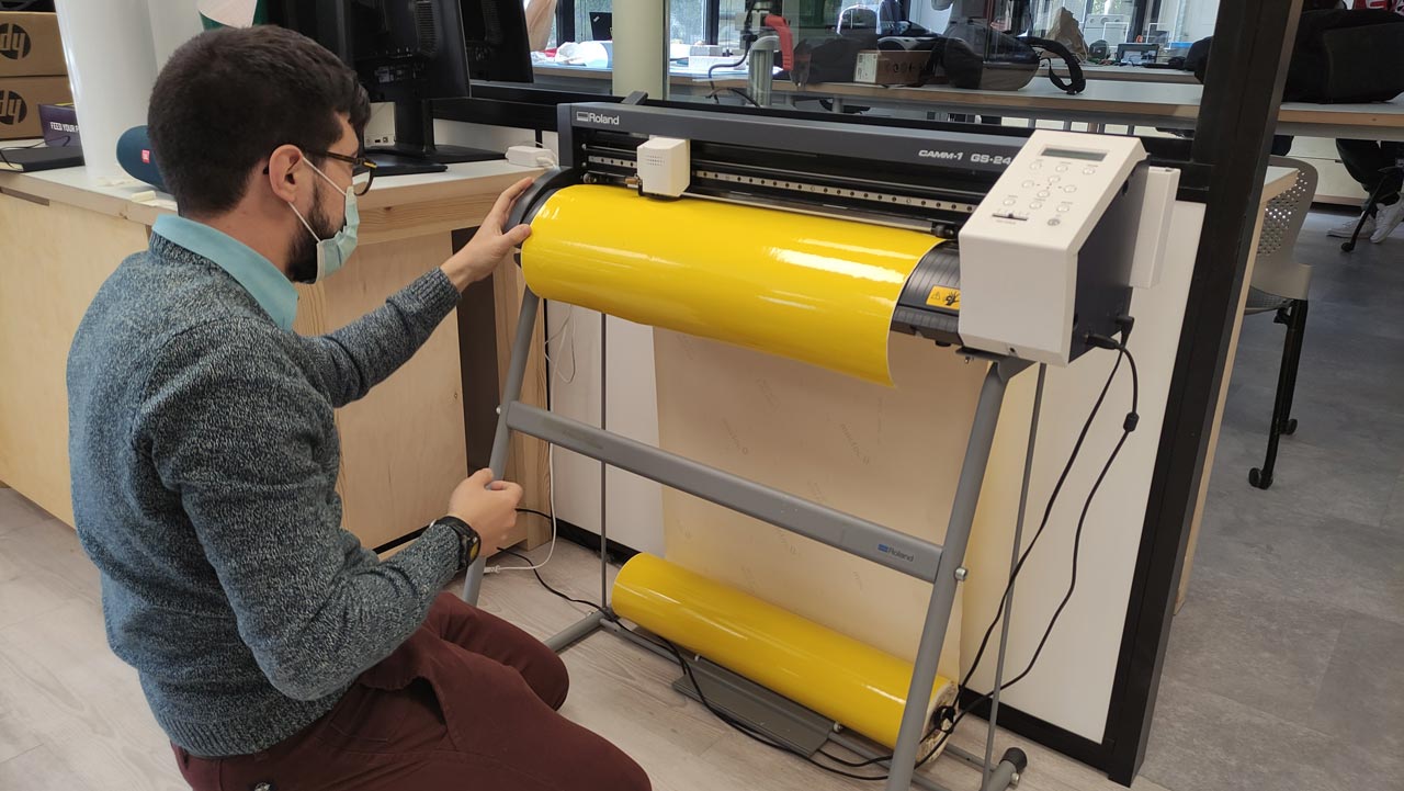
2. VINYL CUTTER MACHINE
The other machine we have been working on this week is the vinyl cutter, a Roland GS-24.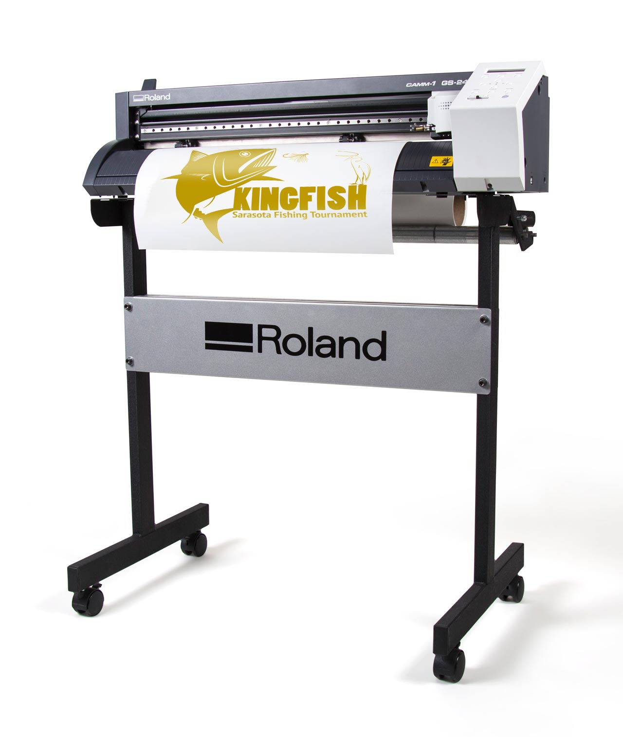
We have to prepare the cutting file in Illustrator. Our FabLab computer already has the drivers installed. In Alberto Gonzalez's assignment you can find a fantastic explanation and an associated tutorial where he tells us step by step how to launch the file. We have been lucky enough to have him demonstrate it in person. We summarize the steps below:
- Place it on the second line from the left.
- Press the orign button (keep the button pressed so that the machine registers the origin).
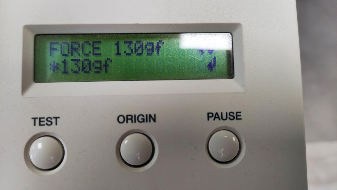
- Force: 130 gr.
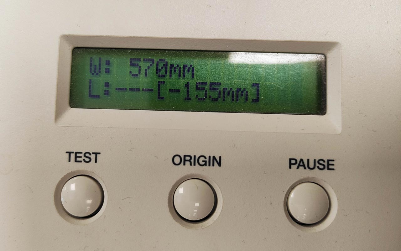
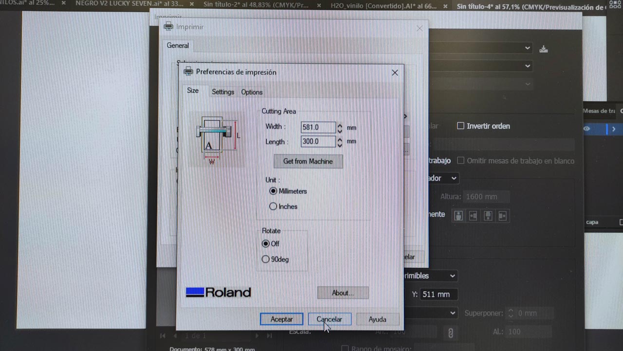
- With: 583 mm. (with this measurement we will have to set the working space in Illustrator.
- Test: make a cutting test.
- We retrace an Origin
- Enter
- Return to Illustrator and launch our file by selecting the Roland GS-24 printer.
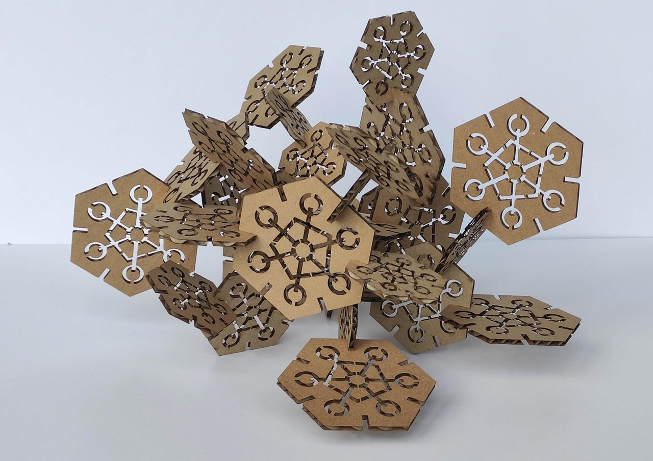
PARAMETRIC PRESS-FIT CONSTRUCTION :: H20 KIT
In our individual assigment we have to design and manufacture a press-fit construction H20 Kit. Below I will show you the associated design and fabrication process.
Designing parametric 2D modelling processes
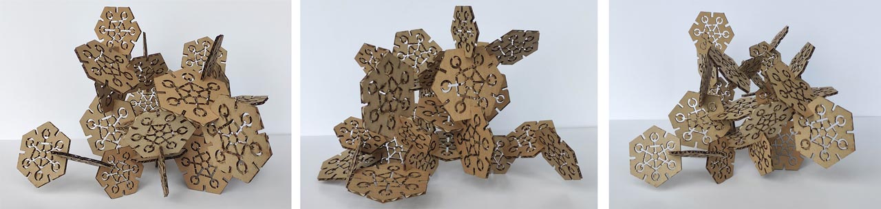
We have to build a press-fit construction kit that can be assembled in multiple ways. This is going to be fun! The possibilities are endless but decisions have to be made to keep up with the intense pace of FabAcademy work.
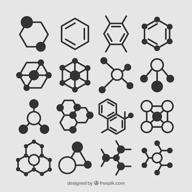
After reviewing projects of other colleagues and reference images, I decide to work on the concept of lattice and its multiple possibilities at the design level, taking as inspiration the molecular structure of water, H2O.
I don't have any experience in parametric design, so looking for interesting projects, I liked the work done last year by Nadieh Bremer, in this assignment. In it she explained in detail the whole process of working with Cuttle, a fantastic on-line parametric design tool for digital cutting machine. We start with the first parametric design.
Cuttle parametric design process
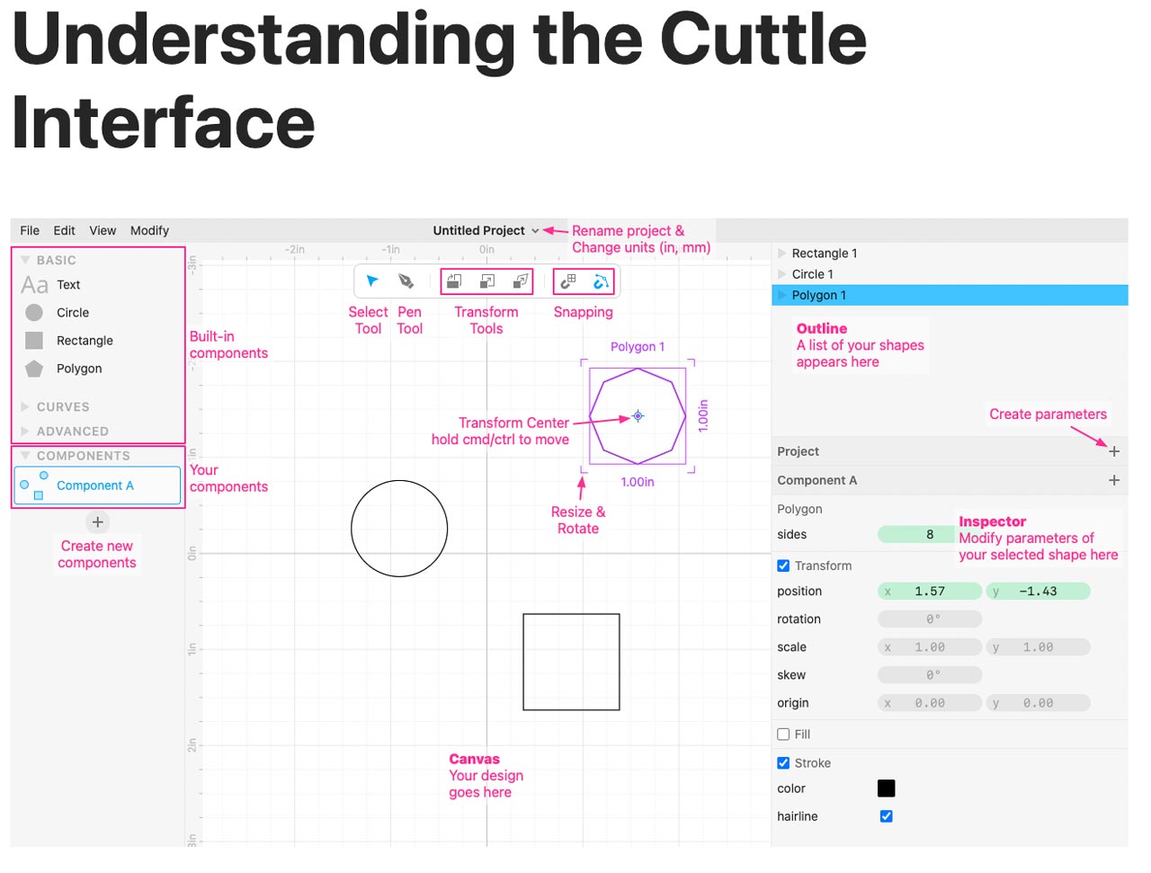
Cuttle offers you the possibility to make parametric designs on-line, just sign-in, and start designing. All your files are saved in your profile and you can download them in .svg and .pdf formats. It is especially interesting to make lattice effects, mandalas or complex geometric patterns, it is important to understand the Cutte interface and know how each tool works.
After doing some tutorials, recommended by the platform itself, I start to make my first parametric design test, to familiarize myself with the program. In the first design I experimented with interesting shapes but I didn't take into account aspects that are important to consider in your final design.
Designing with Cuttle H2O Hexagon
Drag the polygon tool to the workbench. In the side menu you can modify the number of sides and other parameters.
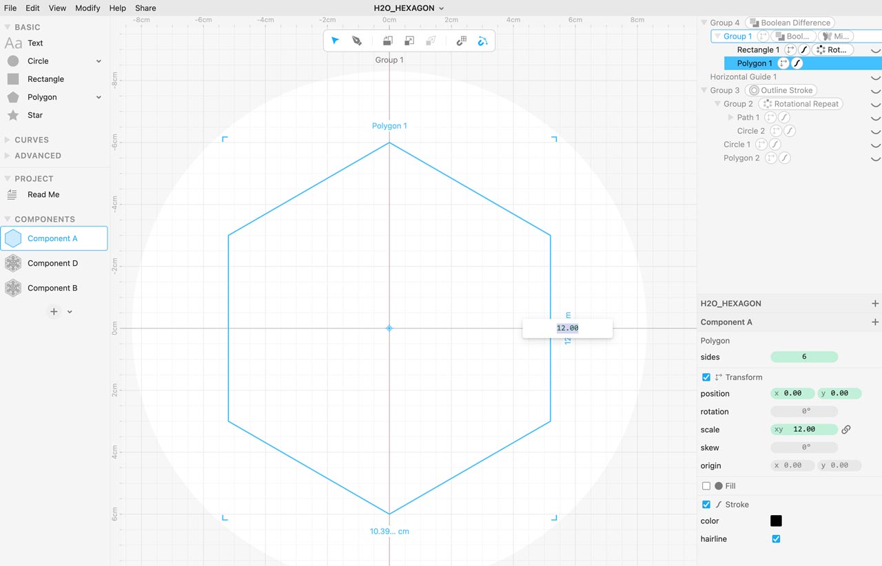
Setting of units of measurement. By default, the drawing is in inches, it is necessary to change it to cm or mm (click on the central menu).
We draw a rectangle that will be our link with the next hexagonal element. This rectangle being parametric we can adapt it once we do the kerf test of our material. When we click on the figure it is edited and allows us to modify measures.
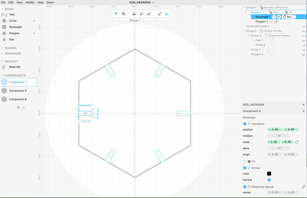
We advance in our design in a linear way and finally we apply the Outline Stroke tool, which allows a parametric offset to see what width is best for your design.
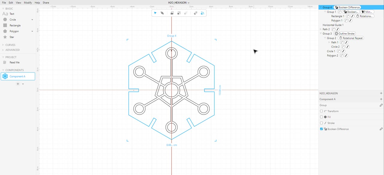
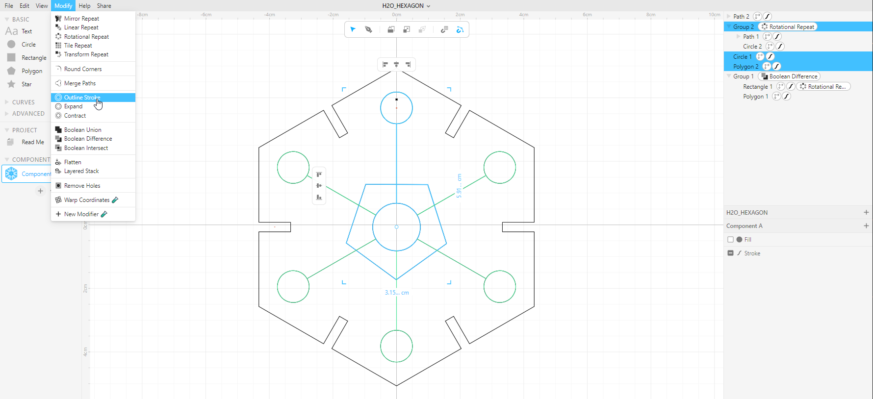
The interesting thing is that you can edit each element independently and parametrically modify its position, rotation, scale, skew and origin, to adjust its design. Once you have your design ready you export it in .svg
Preparing the laser cut file in Rhino
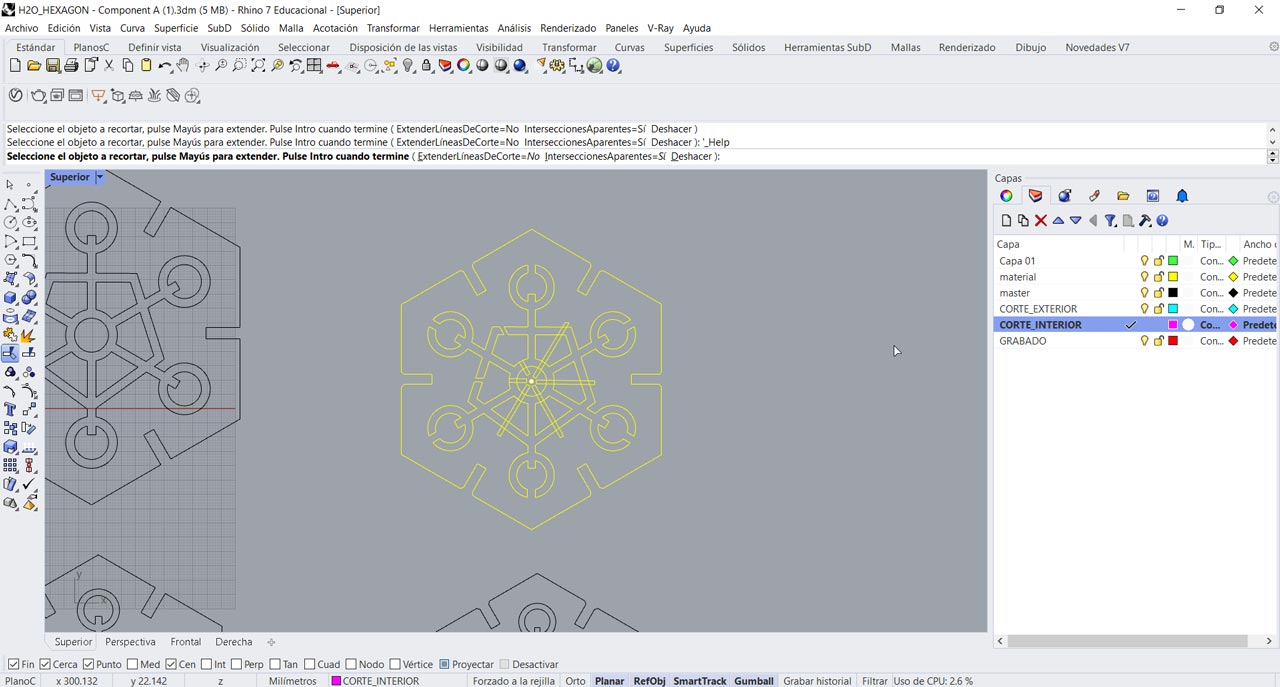
Once the design is done in Cuttle, I import it from Rhino, since it is a program in which I am more comfortable. I prepare all its elements to print on the laser machine, exporting the file as .dxf to be able to open it in AutoCAD (program linked to the laser cutter we have in FabLab UE).
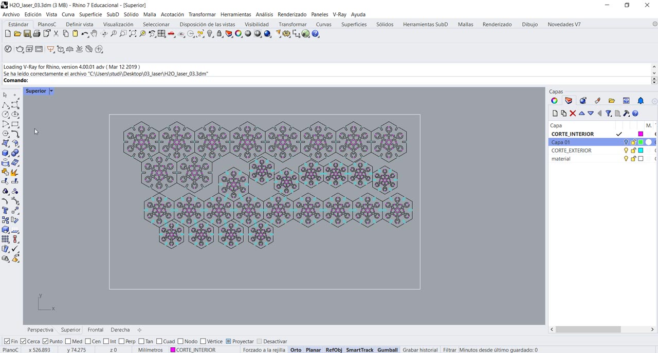
Important: The cutting table of our laser cutter is 80 x 45 cm. It is necessary to draw this space and adjust all the pieces to be cut for a better use of the material.
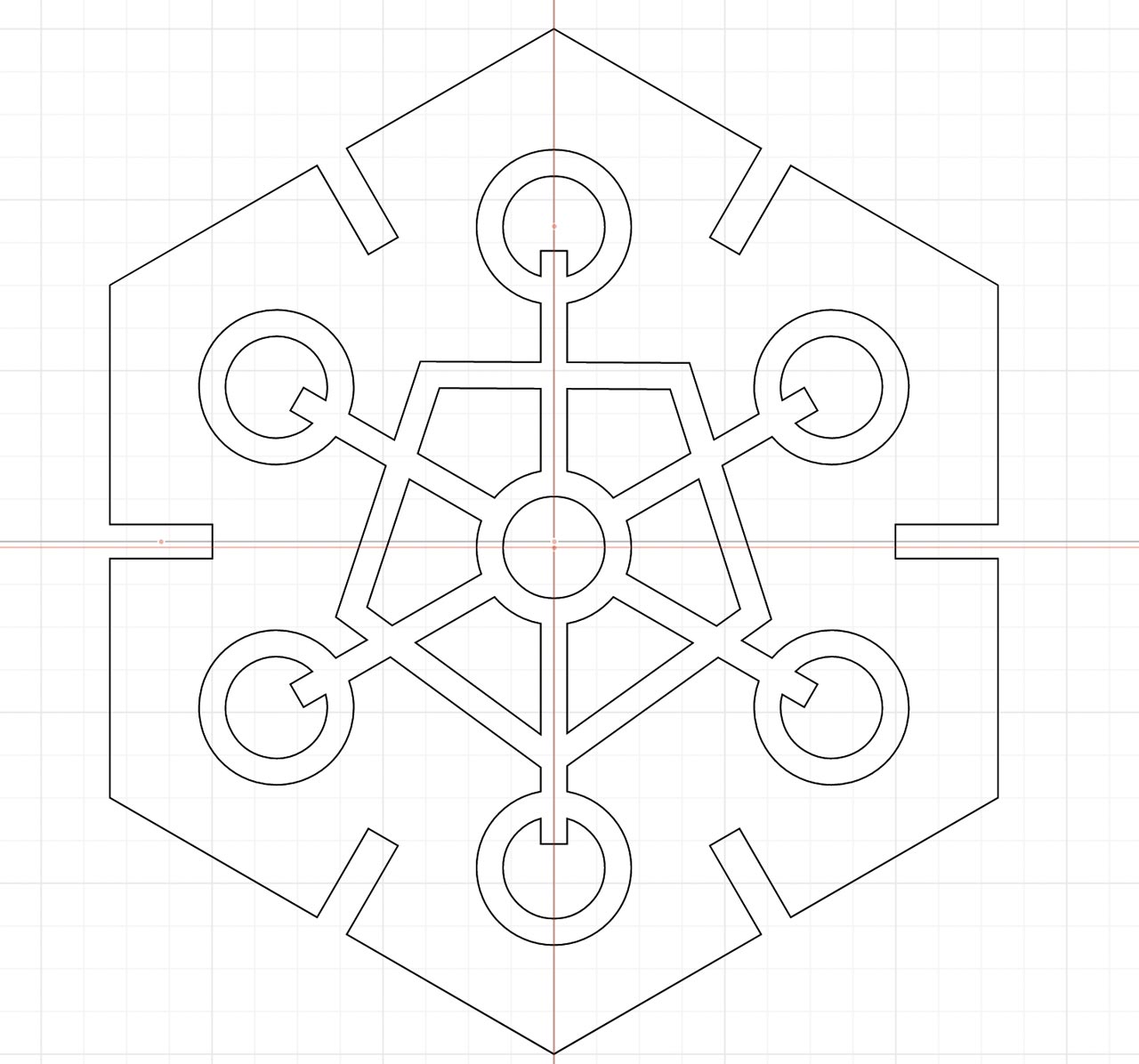
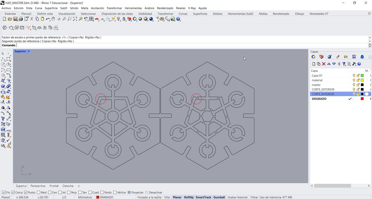
First mistake: When making the design I did not take into account that the central elements would fall down as they were not connected to each other. Therefore, I had to draw some bridges to connect all the interior lattice.
Kerf Testing
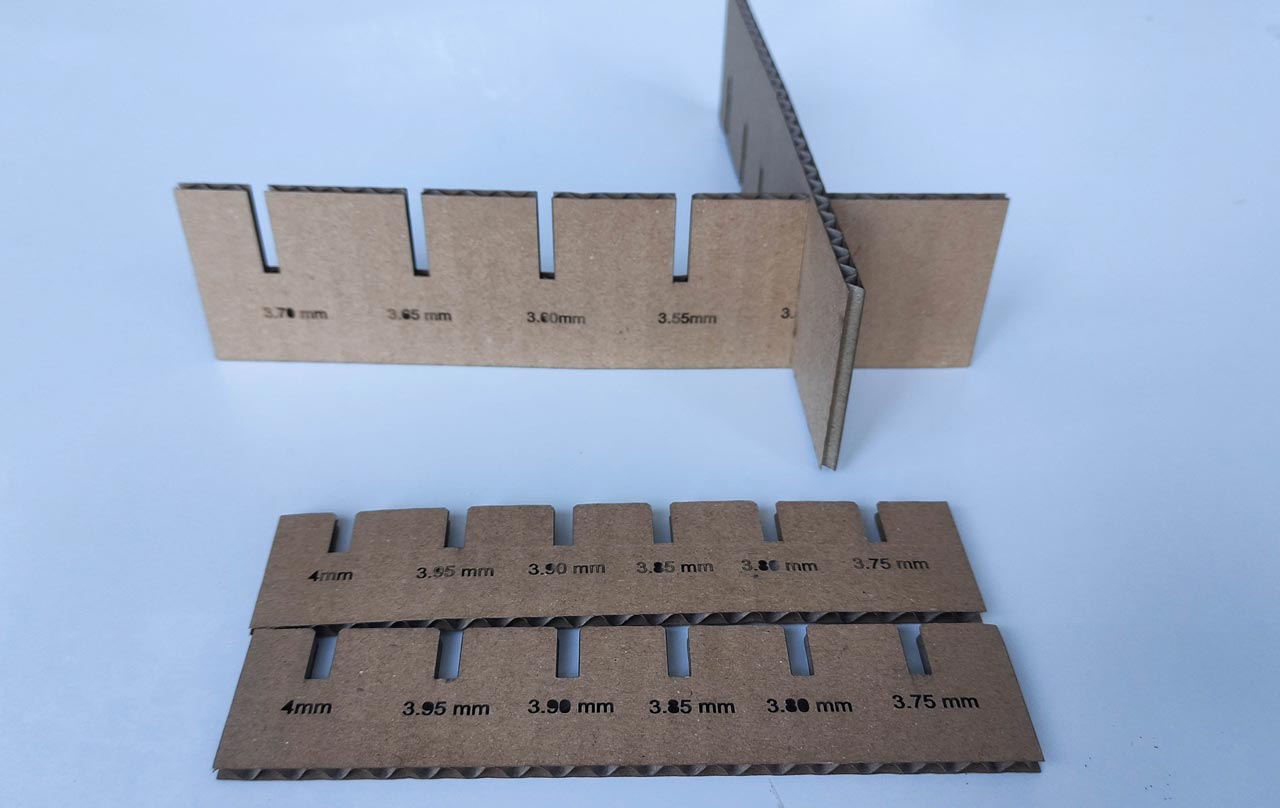
The kerf is the material that is burned away by the laser, it's very tiny, and depends on the material and thickness used. This aspect is very important when we have two pieces that have to fit together.
We have to measure our material, we will use 4 mm corrugated cardboard. It is essential to adjust the Kerf comb well. I had to make two tests, in the first scale that goes from 4 mm to 3.75 mm, none of the parameters adjusted the two pieces. In the second test, which goes from 3.70 to 3.50 mm. In the second test, ranging from 3.70 to 3.50 mm, we see that 3.50 mm is the best fit.
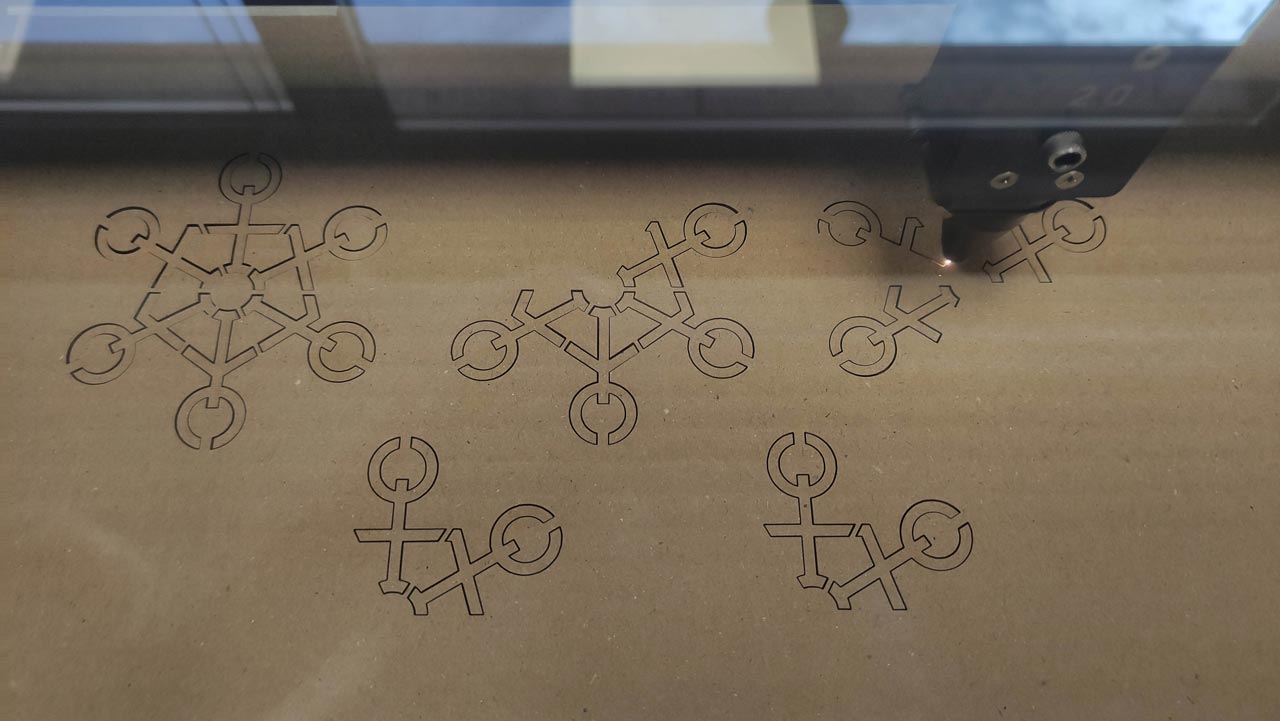
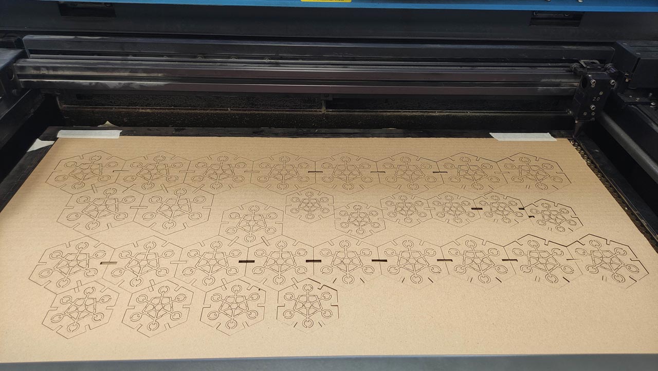
Laser cutting of H2O Construction Kit
Now it is time to materialize our design using the laser cutter in corrugated cardboard of 4 mm. thickness. The FabLab UE has a template with the layers, colors, thicknesses already set.
- We open the template in AutoCAD, import our Rhino file (previously saved as .dxf), copy and paste it into our template, and set each layer in its corresponding color and thickness. Important: apply the following commands for a good result in the laser machine:
EXPLODE(it explodes the lines of our drawing independently).OVERLOAD(removes duplicate lines so that the laser cutter does not go over the same line twice and can make mistakes and take more time).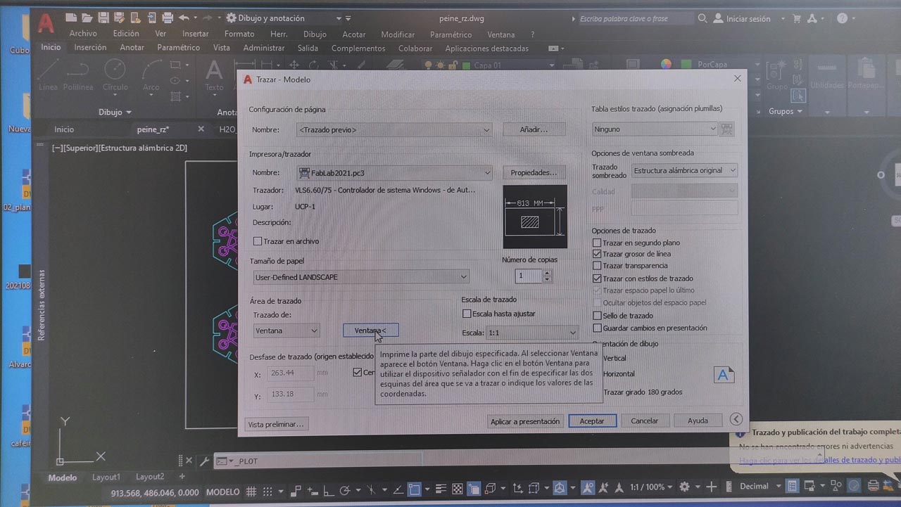
- We launch our file to the laser cutter.
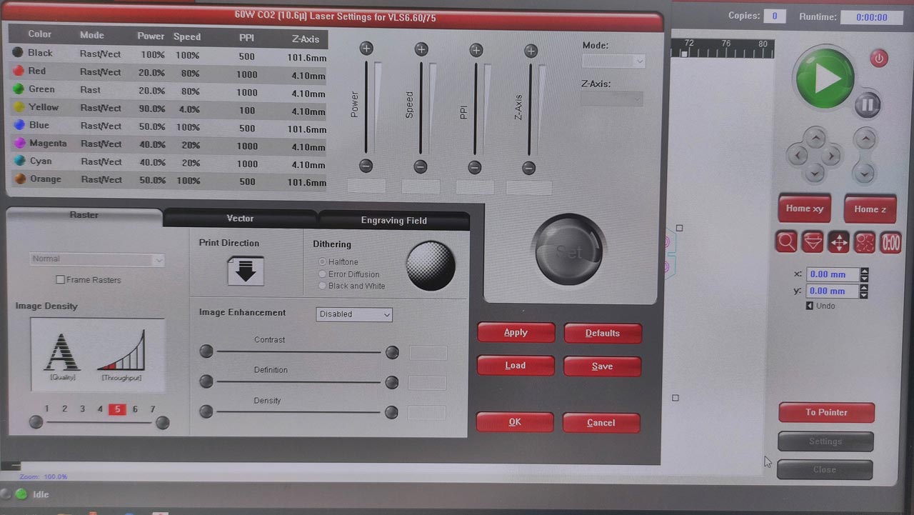
- In the interface of our laser, we set the cutting settings. We have a library of materials in our Fablab. It is always a good idea to do a test run beforehand in case you need to adjust the settings. The configuration we have used is:
| Power | Speed | PPI | Z-Axis |
| 40% | 20% | 1000 | 4.10 mm |
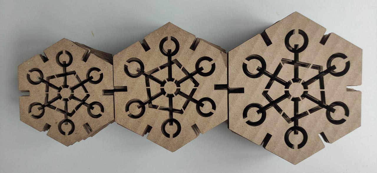
And this is the result!!
What went wrong
It is necessary to give a larger chamfer to the connecting rectangle from one piece to another, in my design it is a little tight.
The 4 mm. corrugated cardboard is very weak. It is very weak if you generate many gaps in the design it becomes very delicate to manipulate.
It is necessary to make bridges between the interior holes to hold them to the main hexagon. In the first file I didn't do this and had to redo it.
What went well
After cutting the design twice all the hours spent on the design come to fruition and the laser machine does its job. If we made a mistake, we have to go back to the beginning. I love to see the precision and speed with which this machine works. Attached is a video of how it works.
This is a video of the laser machine working!
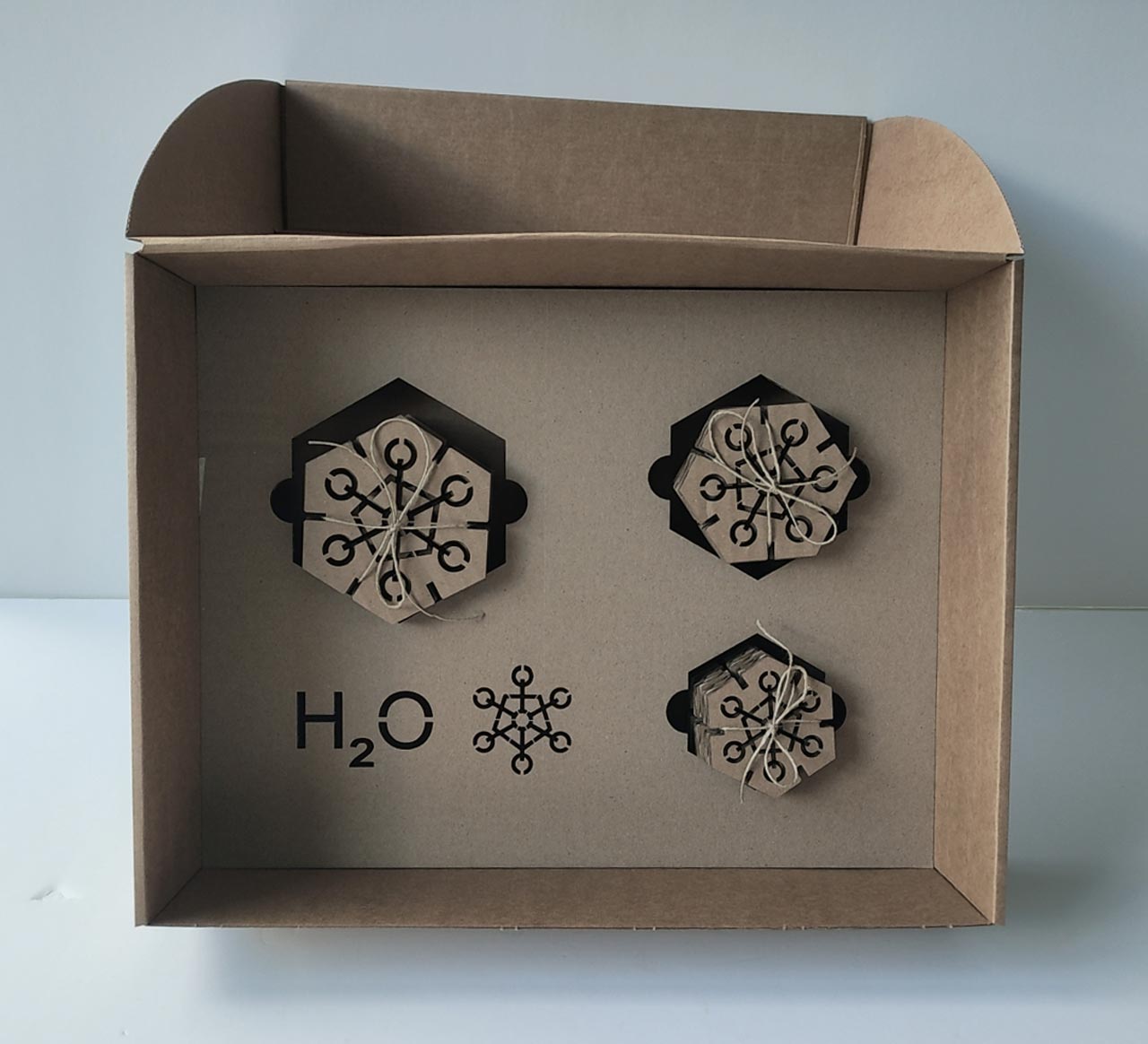
And this other video show you the Packaging of the project
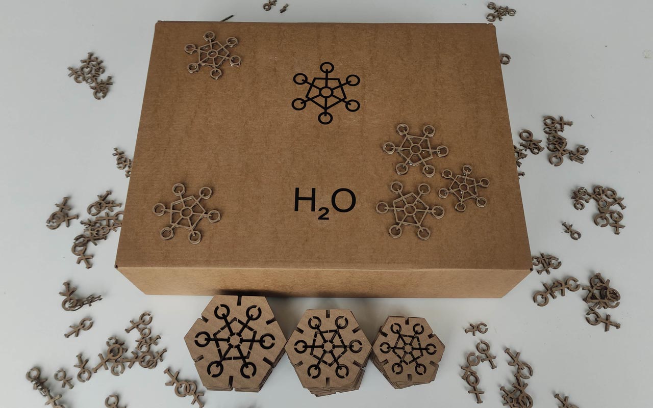
H20 Vinylcutter
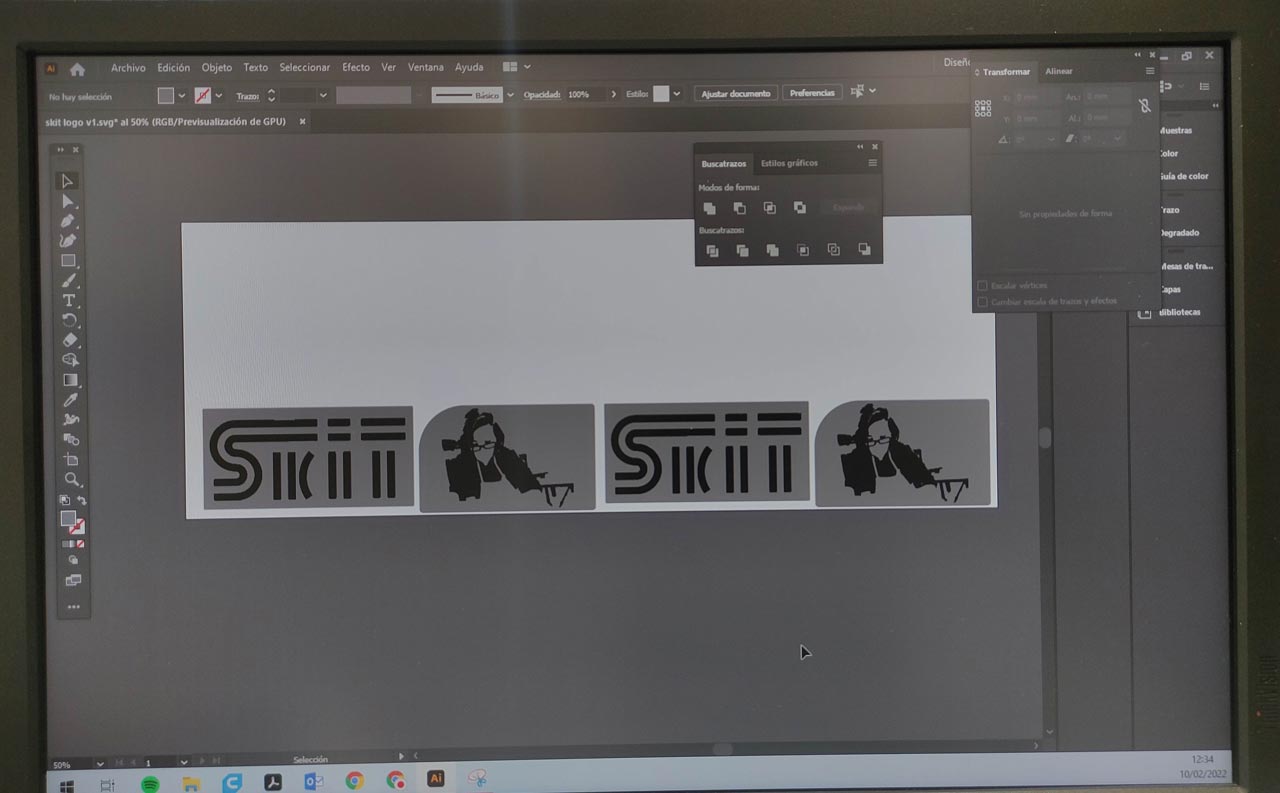
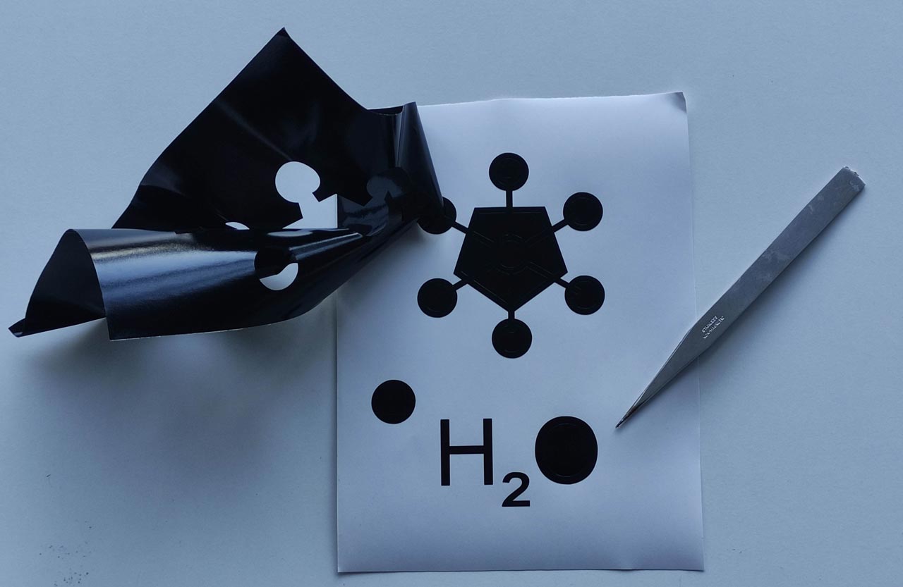
As we are making a Construction Kit, I thought I would store the whole kit in a box designed for that purpose. So in the vinylcutter test I'm going to cut a black vinyl image and text to apply to the presentation box.
- Load the black vinyl into the Roland GS-24.
- We make the corresponding test, as we have been taught in the group demo.
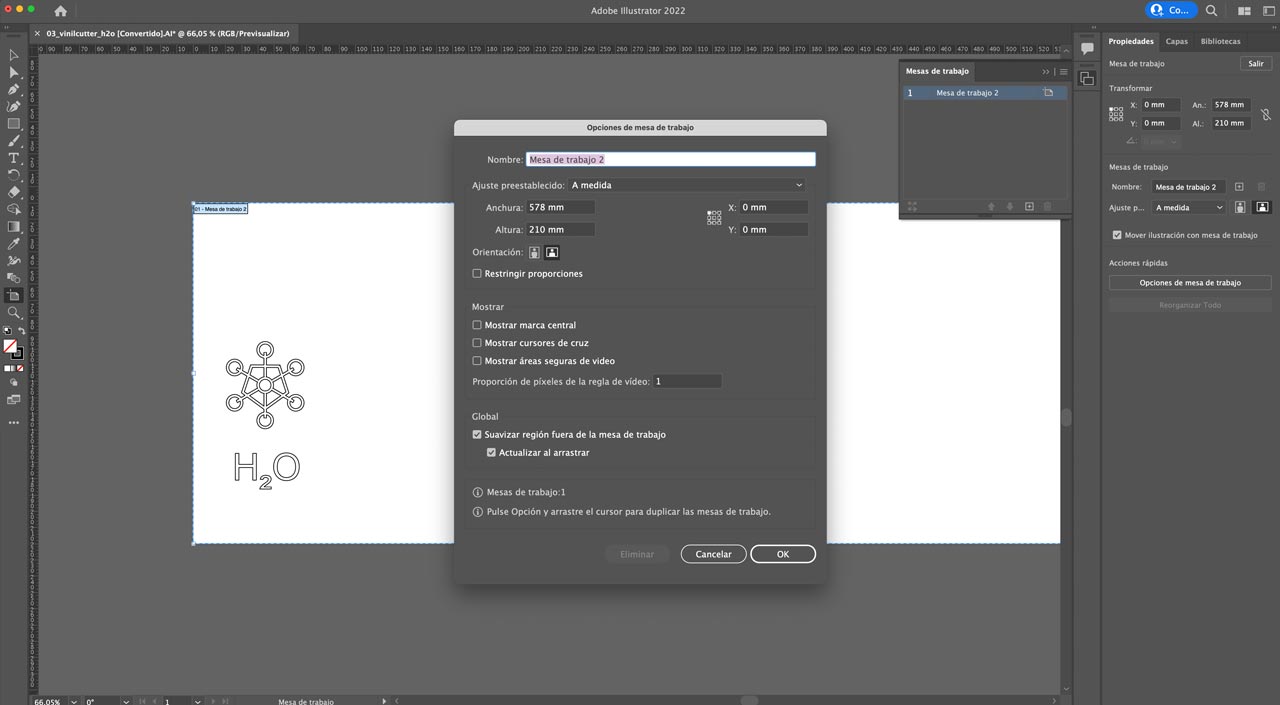
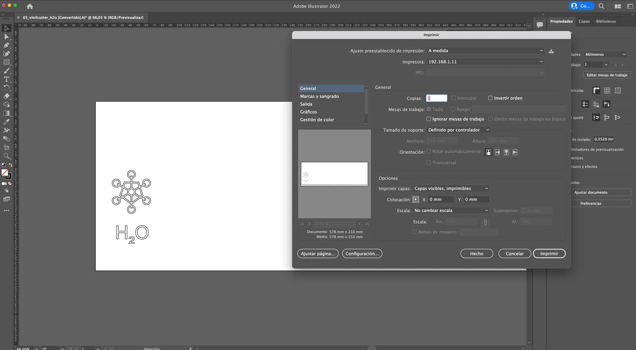
- Open the file in Illustrator. To prepare the print, I follow the instructions given by our instructor, Alberto González, and review a detailed tutorial he has on his website with the steps to follow (very well explained). Indispensable video if you have no experience with either Illustrator or the vinyl cutter, like me :(( The important part when you send to the printer, it is to set the working space to the measurment of the with of the vinyl.
- We launch the file to the printer.
You can find some images of the process.
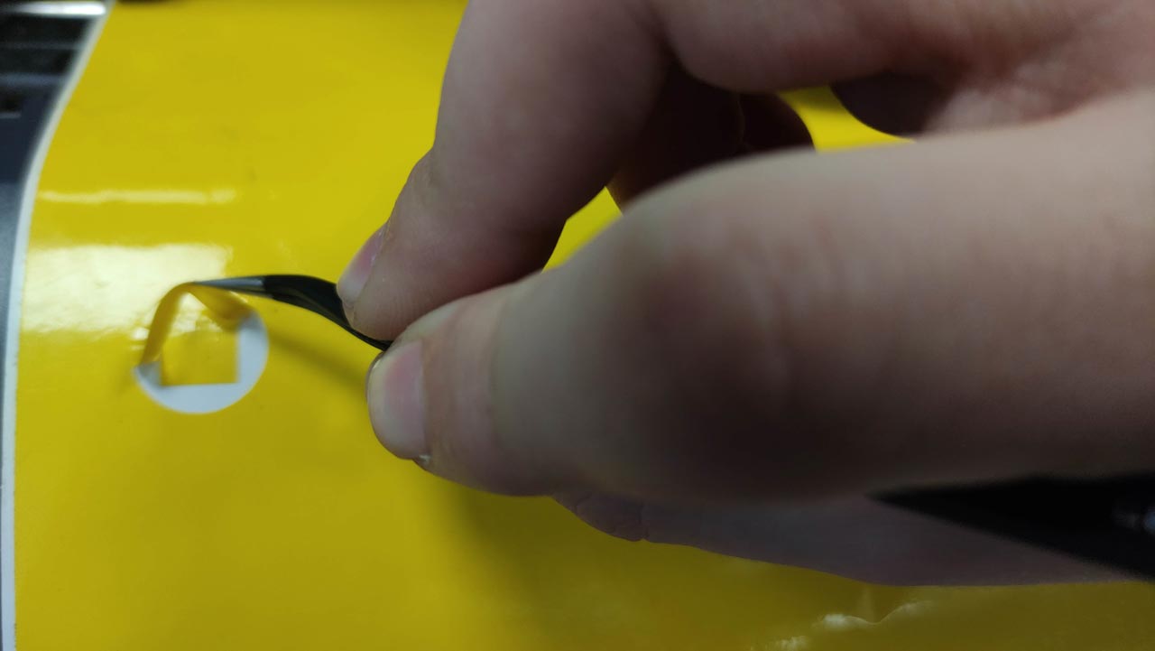
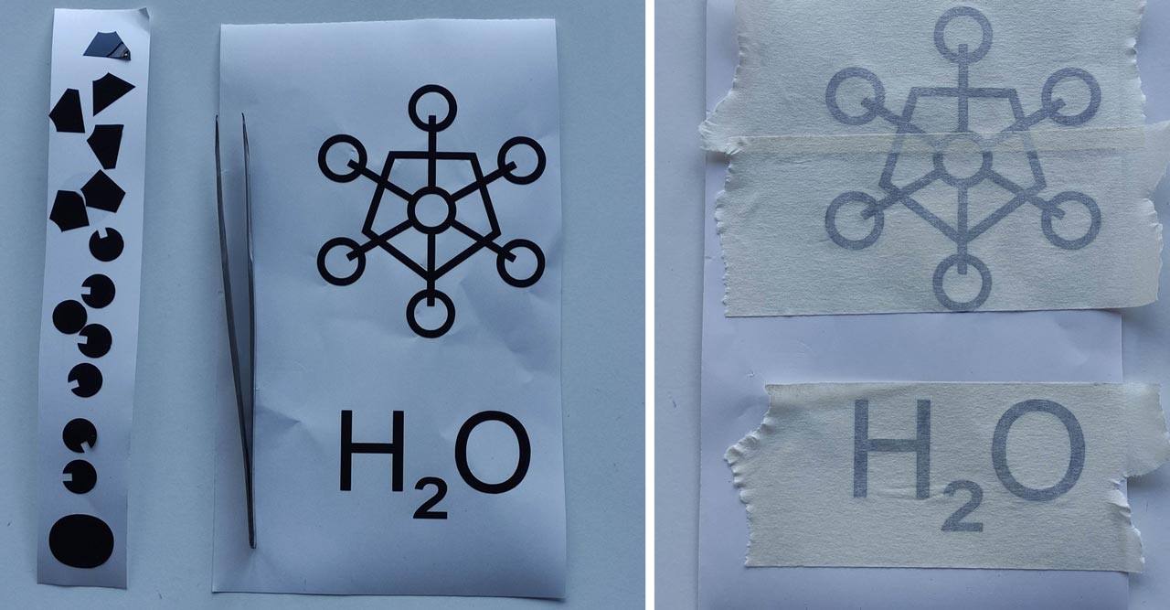
Once we have our vinyl cut, we remove with tweezers the part that we are not going to use. We put the carrier paper (it can also be replaced by overlapping masking tape) and position it on the surface to be vinylized. Apply pressure with a card and peel the carrier paper carefully and diagonally so that it does not lift from the surface we are vinyling. This is the result.
And you can find here the Time Lapse of the project.
FILES
H2O Construction Kit
- Cuttle page with the three shapes (parametric): link
- SVG of the shapes (non-parametric): hexagon A link; hexagon B link; hexagon C link
- DXF of the development of the Construction Kit (non-parametric): link
- DXF template FabAcademy UE laser machine: link
- DXF of the kerf proof (non-parametric): link
- AI of the vinilo H2O: link
H2O Vinilo
- AI of the design (non-parametric): link
Table of Contents