04 Week :: ELECTRONIC PRODUCTION

One month into FabAcademy, we are entering our fourth week: Electronic Production. I have no prior knowledge of electronics, so I'm afraid it's going to be a tricky assignment; although the ISP fabrication and soldering part, I'm going to like it!
WEEK CHALLENGES
Group assignment:
- Characterize the design rules for your in-house PCB production process: document feeds, speeds, plunge rate, depth of cut (traces and outline) and tooling.
- Document your work (in a group or individually).
- Document your work to the group work page and reflect on your individual page what you learned.
Individual assignments
- Make an in-circuit programmer that includes a microcontroller by milling and stuffing the PCB, test it to verify that it works.
Have you answered these questions?
- Linked to the group assignment page
- Documented how you made (mill, stuff, solder) the board
- Documented that your board is functional
- Explained any problems and how you fixed them
- Included a ‘hero shot’ of your board
GROUP ASSIGNMENT
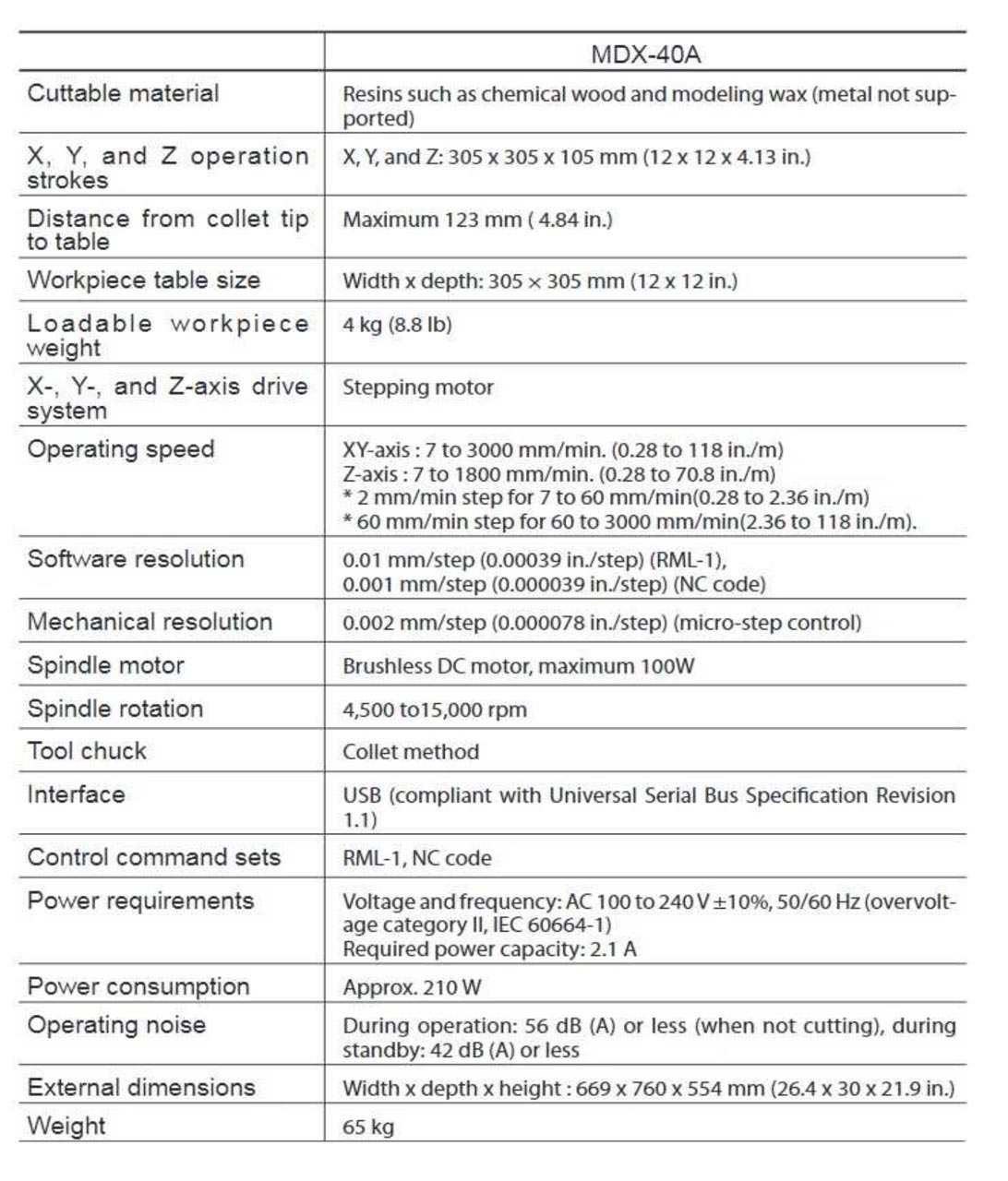
For this second grupal assignment, my "fabmates" Pedro Chana and Jon Merino and I have to characterize the design rules for our in-house PCB production process. In our FabLab FablabUE Madrid, we are going to use the Modela MDX-40A, special thanks to Pedro, who is the great documenter of the group!!
1. PCB DESIGN
To start with this week´s assignment, after reviewing some past repositories Alberto Gonzálex, Adrián Torres, Lorena León, we had a test hand-on tutorial with our instructor, due to the fact that it seems that the most frequent used program to work with, called fabmodules, doesn´t give online support anymore, so, we have to use modsproject.org (mods CE) instead with our MDX-40A.
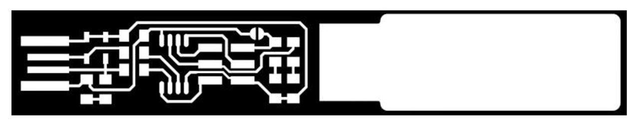
So, our first step is to transform our traces, and board outline .png to .rml files. To achieve this, we plan and decide to build Brian´s FabTinyISP by following, firstly these steps in modsproject.org:
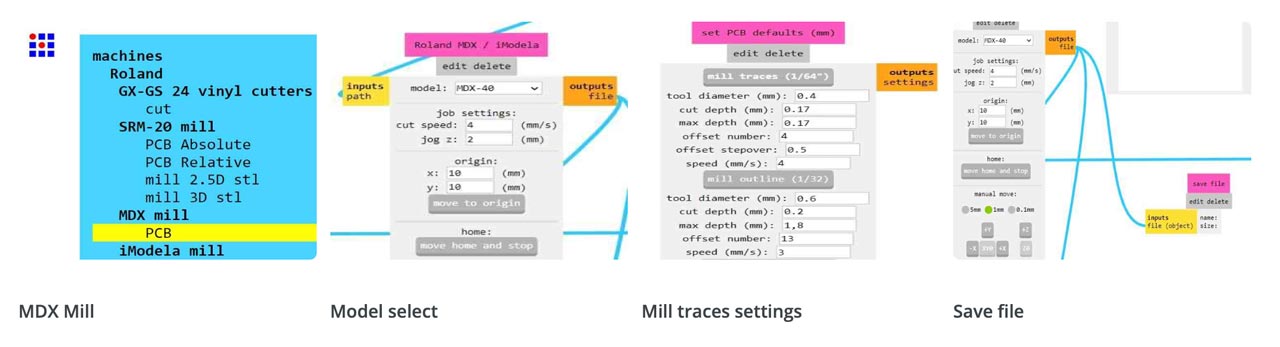
- Open modsproject.org
- Open program -> machines -> MDX Mill (PCB).
- Load your traces .svg or .png file with 1000-dpis. It´s important to do it at first, or your PCB settings changes won´t be recorded.
- Select in Roland MDX/iModela the MDX-40 Model. Adjust origin as needed.
- Configure your mill´s traces or outlines, depending on your file: Tool diameter, cut depth, max depth, offset number and speed.
- Click on the grey button above the chosen setting, so they will be established: You can check in the mill raster 2D values.
- Create a new module -> modules -> open module -> file save.
- Click in mill raster 2D -> CALCULATE: A toolpath view of your design will appear.
- When you click CALCULATE, a download window will appear. Rename you file, that´s going to be saved with a .rml extension.
- Open file in the Modela MDX-40A VPANEL: We´ll check this further on.
- We have to do the same with the other file: outlines.
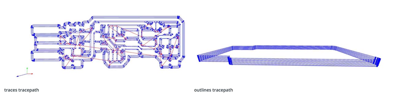
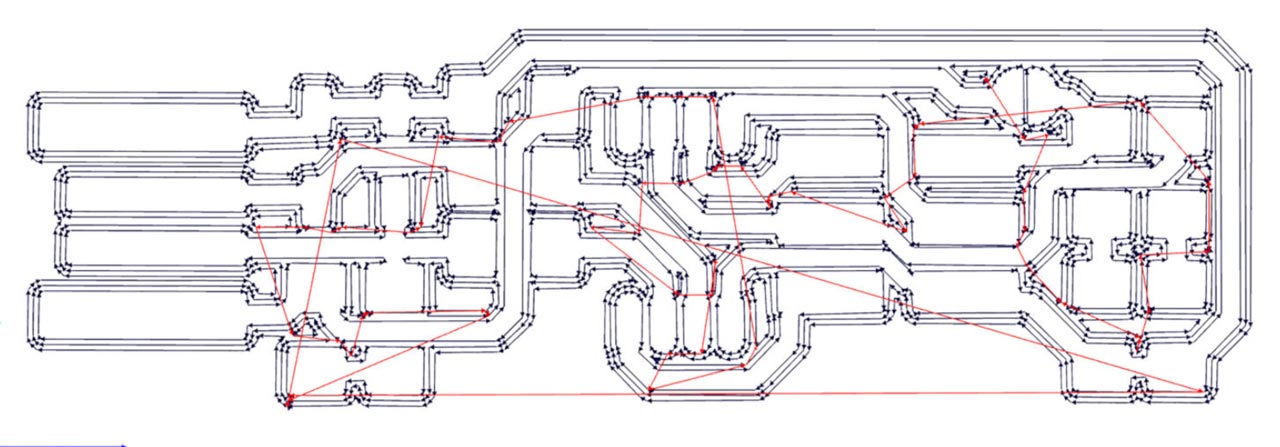
Here below you can see the toolpath view of your design once you click CALCULATE. Blue lines are the milled lines, red lines not, they´re the mill direction/path. These image is very useful because you can check that your cut depth is correct, that will help you avoid breaking milling cutters, specially in the outline file.
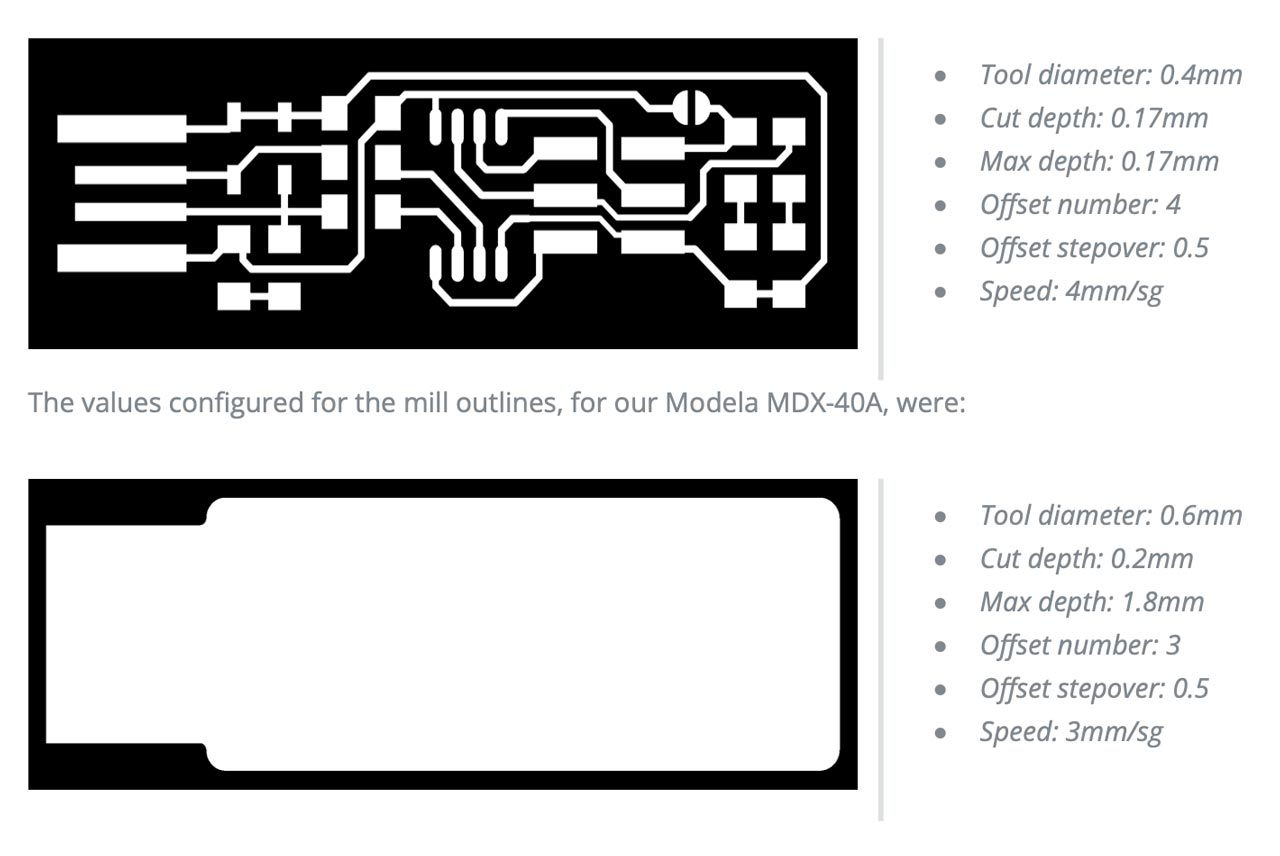
For first impressions, it was a surprise to test a program not used before by our instructor, once you understand the settings needed to configure, in order to cut later in the Modela MDX-40A, it´s an easy protocol. Probably, the most important part is to know before hand the milling tool diameter that your going to use in every part of the process (traces and outlines) and the PCB clad board to use.
In our case, we are going to use a copper FR1 clad blank board and the setting established for the traces, in our Modela MDX-40A, were:
2. MODELA MDX-40A + PCB PRODUCTION PROCESS
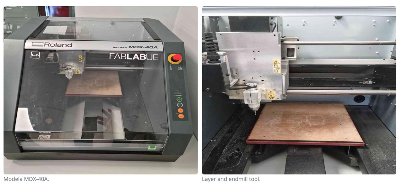
Now that we´ve got our .rml files ready, it´s time for the next step on this week´s assignment. First of all, let´s have a look to our Modela MDX-40A:
SAFETY PROCEDURES
This device is designed for laser milling, and it needs to follow some general requirements to ensure that no damage is done:
- Check always that the cover is closed, if not, the machine won´t start the milling process.
- Remember that the end mills are sharp tools, inadverted contact can cause injury.
- Never touch the spindle head after milling, it can be at high temperature.
- Never use a pneumatic blower: cutting waste may get inside the machine and cause fire or electrical shock.
- Never operate the laser system without constant supervision of the cutting and engraving process.
- Never leave materials in the laser systems after the laser processing has finished
The Modela MDX-40A is a milling machine that can, basically, be divided in two specific parts:
The workpiece table, or the layer where our copper FR1 clad is going to be set.
The spindle head, were you´ll change the endmills and calibrate the Z axis for the VLS.
3. PCB PRODUCTION WORKFLOW
So, to start with the Modela hands on, first of all we open the VPANEL (a dedicated program for controlling the machine) in our windows computer. From this program we´re going to be able to move the table in the Y axis, and the tool in the X and Z axis. And it´s also the program where we´re going to set our (0,0,0) coordinates. So with the help of the VLS program we:
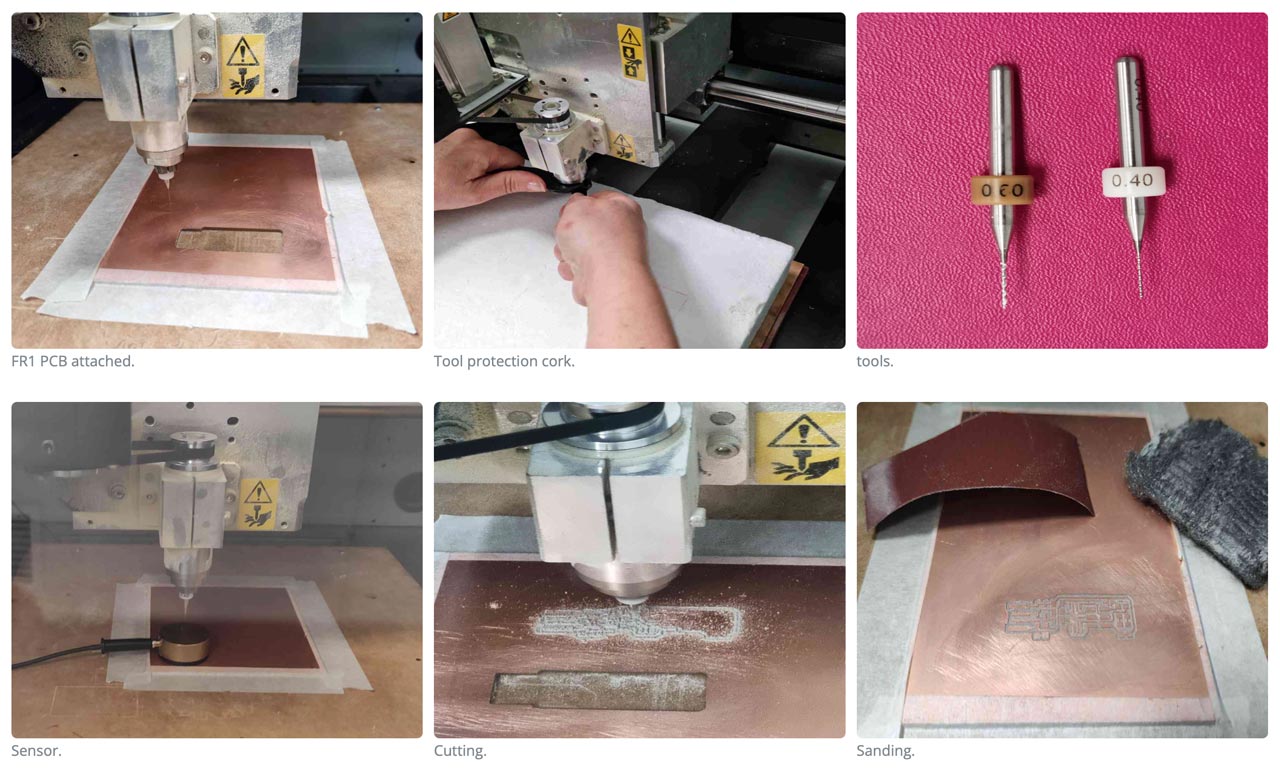
- Open the Modela MDX-40A lid and attach our PCB FR1 clad with masking tape: It´s important to seal it strongly.
- Change the tool for milling: It´s important to protect the tool from falling and breaking. Grab firmly and lower gently. To tightening, snug gently.
- To change the tool: Use the two wrenches, don´t touch the tip of the tool (it can break!), close without putting too much strength.
- When changing tools, the big wrench on the left and the right wrench on the right, close them together to loosen up. Put the wrenches on the other hands and you will tighten the tool.
- When changing tools, the big wrench on the left and the right wrench on the right, close them together to loosen up. Put the wrenches on the other hands and you will tighten the tool.
- Go to the VLS: Set X,Y origins with the VLS control pad, and once set, go to XY-> APPLY.
- To set Z origin: Use the Modela Sensor (Set on top of the PCB FR1) and detect. Don´t forget to remove the sensor and the cable after.
- Check the RPM´s: In our case, we settled them at 15.000RPM´s.
- Press CUT in the VLS: Select the .rml file to cut.
- Press OUTPUT to start cutting. DON´T FORGET TO CLOSE THE LID!
- Once the cutting has finished, it´s important to vacuum to remove the cutting waste.
- Clean and sand the piece.
- Start again with the outline file: Don´t forget to change the tool, and set Z to it´s new origin.
Mistakes done!!: It gave us (the three of us!) a big headache and some precious time to start milling properly. The issues we encountered were that the first PCB FR1 board that we used was combed, but we didn´t notice until the first mills. Secondly, we didn´t realize that the X,Y settings on mods CE are preestablished in 10mm, and that took us some time to figure it out as well. In this case, you need to re-do your .rml file with the desired X,Y settings. We also had some issues with the tools, we broke our first one because we didn´t check on the toolpath view (mods CE previously explained above) the cut depth for the outlines, so we gave it too much depth at first (you can check it on the video below). The second tip we broke was a mystery because we double checked everything but it still broke at the first touch with the board during the milling, but it worked well at the second attempt. But once everything was sorted out, the milling went fine since then.. and hopefully will stay this way..!
INDIVIDUAL ASSIGNMENT
FabTinyISP
Our challenge is to make a FabISP. What is a FabISP? A FabISP is an in-system programmer for AVR microcontrollers, designed for production within a FabLab. It allows you to program the microcontrollers on other boards you make, using nothing but a USB cable and 6-pin IDC to 6-pin IDC cable.
To make the board we follow Brian´s FabATtiny 45 tutorial, and we use the png boards to mill it on the machine. See the grupal assignmet for details!
1. MILLING THE PCB BOARD
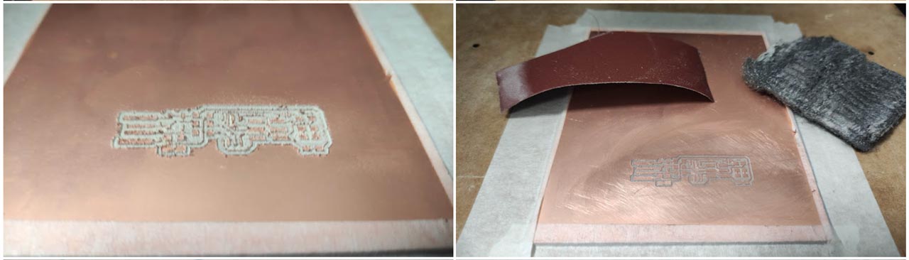
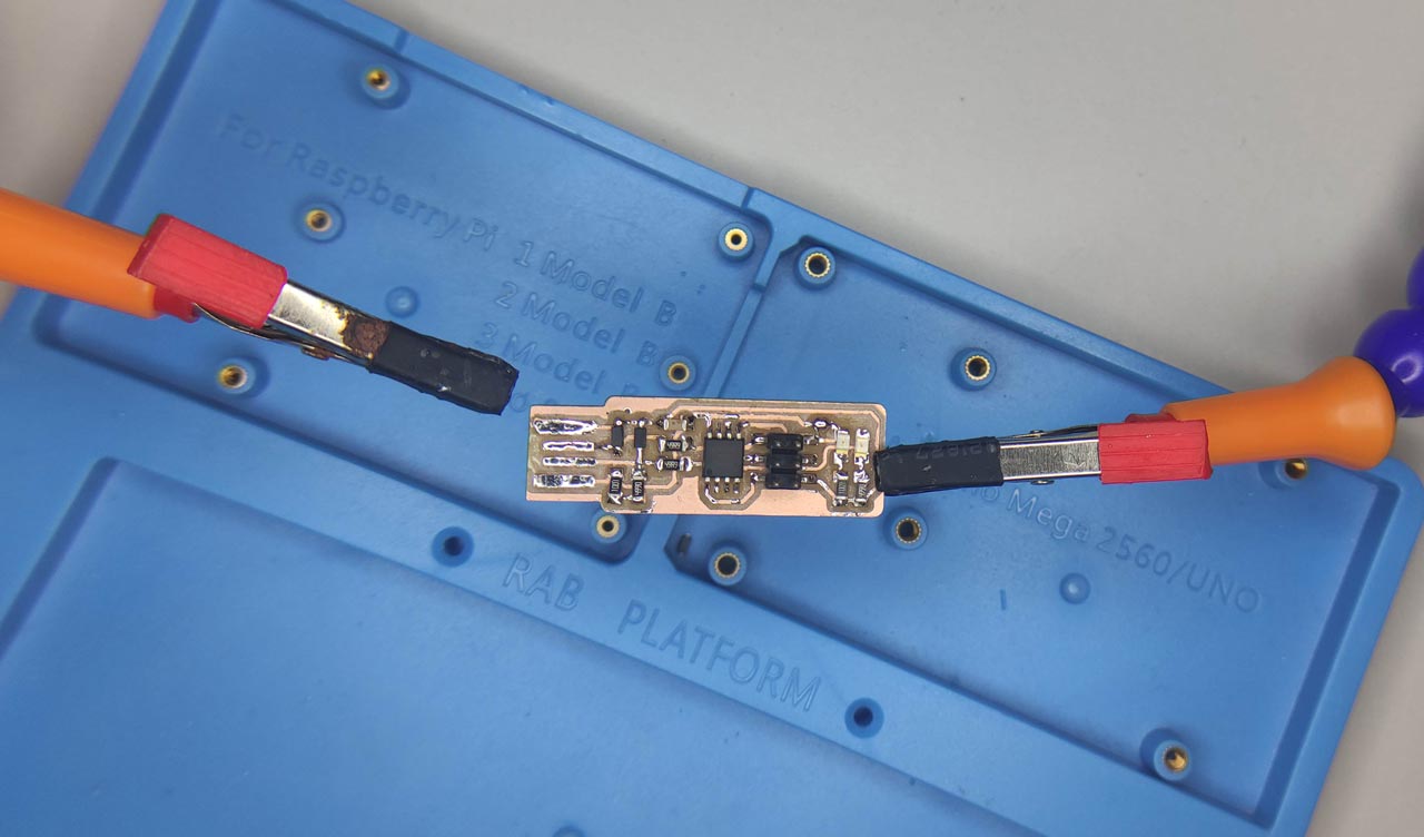
In our FabLab we did the milling in the group assigment, after breaking two milling cutters to get our three boards, this is the result. All the steps to follow are described in the group assignment.
Here is a video of the process.
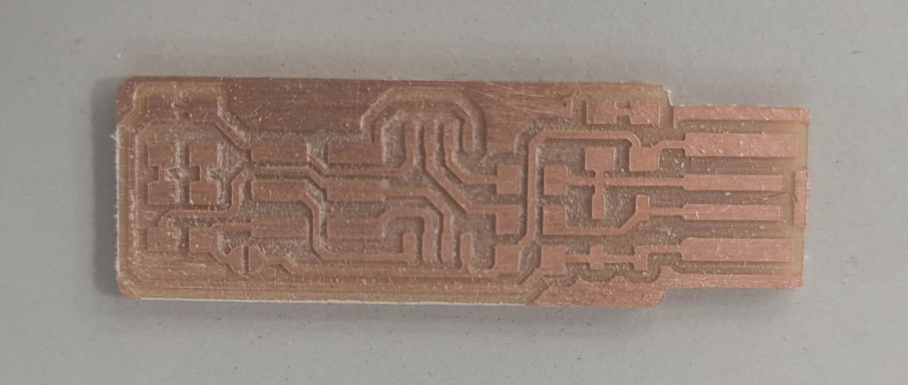
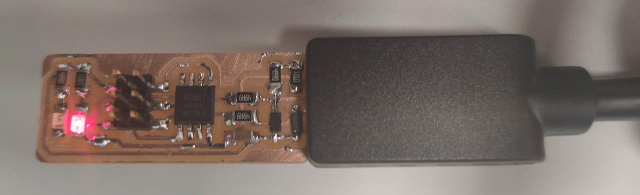
And this is the result!
2. SOLDERING FabTinyISP COMPONENTS
To solder the components on the board, we had the electrical and graphic diagram, at hand, to locate the components correctly and we must take special care to place the components with polarity (LEDs, ATtiny 45 and the Zener Diodes).
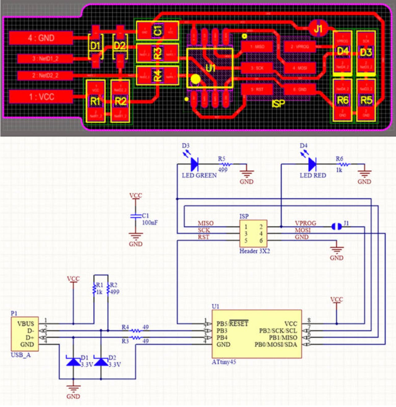
To compose the FabTinyISP we need:
- 1x ATtiny45
- 2x 1kΩ resistors
- 2x 499Ω resistors
- 2x 49Ω resistors
- 2x 3.3v zener diodes
- 1x red LED
- 1x green LED
- 1x 100nF capacitor
- 1x 2x 3 pin header
Once selected our components, with a good pulse, good light and magnifying glasses, we get down to work with the soldering. I have to admit that I had never soldered electrical components and I loved the experience, it is amazing to see how the tin flows through the tracks. Let's hope it works!
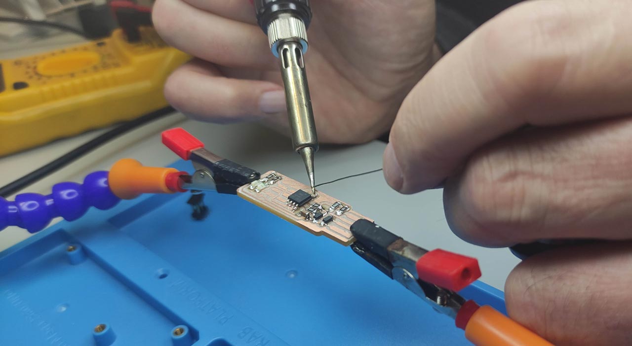
Important: Solder from inside to outside or left to right. Put some tin on the track, place the component on top, reheat to fix, and then go to the other end. If you put the solder on the two points to be soldered, you will probably get some lumps and it will be difficult to put the component flat, as happened to me with the soldering of the first component.
FILES
Table of Contents