5. Electronics Production
Objectives
- I have to make an in-circuit programmer by milling and stuffing the PCB, test it, then optionally try other .PCB fabrication process.
Group Assignment Group Assignment page
- To characterize the design rules for our PCB production process: document feeds, speeds, plunge rate, depth of cut (traces and outline) and tooling and document our work.
The Fifth week’s class of my fab academy life took place and the professor Neil class started as usual,this week assignmend as khown as 3D Scanning and printing
Group Assignment
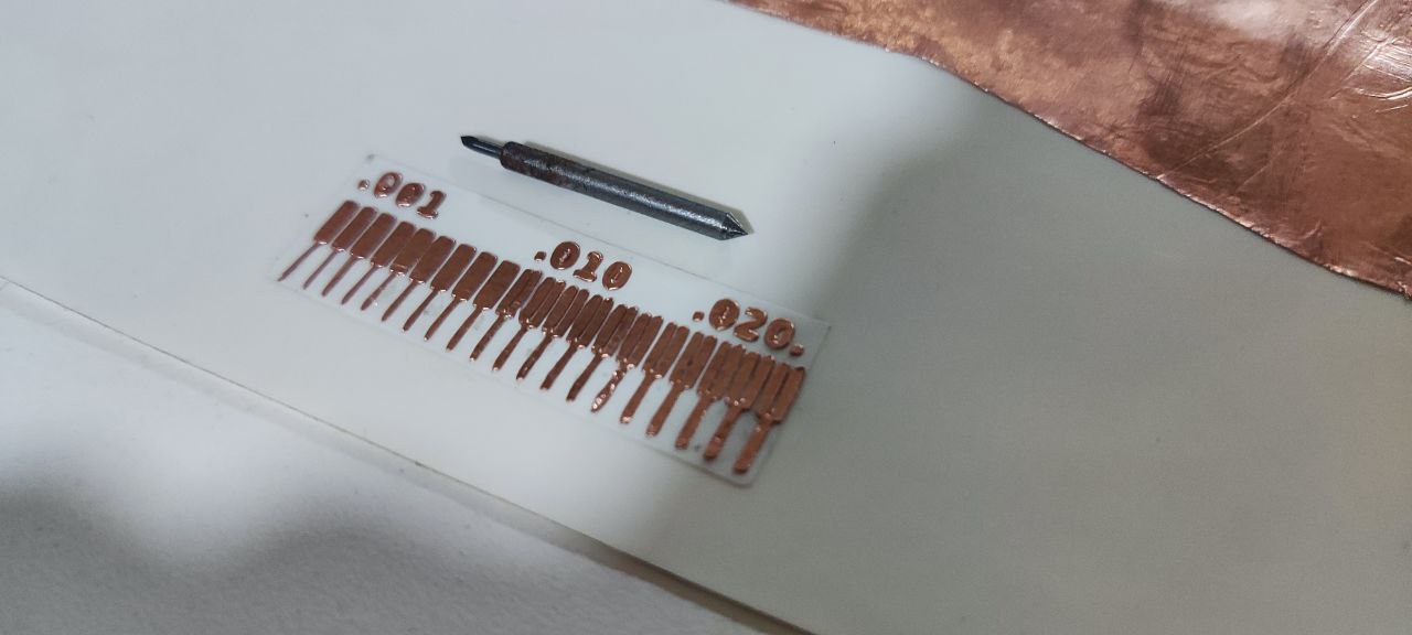
 For this we used the PCB Milling Machine with the 1/64”, 1/32” and 1/100” toolbits and the results.
 After the examination, we came to the conclusion that
- 1/64 bit can trace upto 0.16 mm
- 1/32 bit cannot be used to make traces better to use as a cutting tool
- 1/10 bit can trace upto 0.11 mm
This week’s assignmend I used the milling machine is Modela MDX20 Machine.
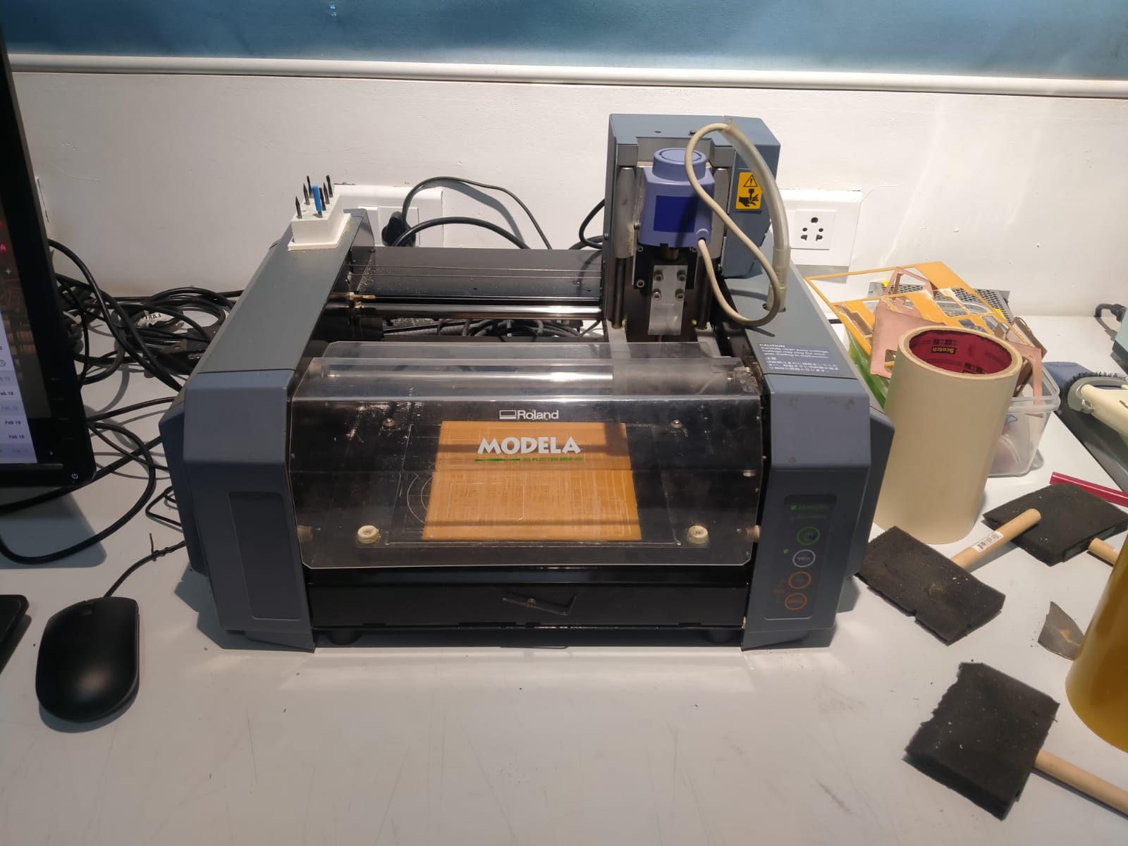
 For milling the circuit I used a Roland MDX-20. The Modela MDX20 is a Desktop 3D scanning and Milling machine by Roland. Easy to use,Compatiable with popular softwares.
Work area 203.2 x 152.4 mm
Z stroke 60.5 mm
Spindle speed 6500 rpm
For milling the circuit I used a Roland MDX-20. The Modela MDX20 is a Desktop 3D scanning and Milling machine by Roland. Easy to use,Compatiable with popular softwares.
Work area 203.2 x 152.4 mm
Z stroke 60.5 mm
Spindle speed 6500 rpm
In two types of milling are available
Climb Milling
Conventional Milling
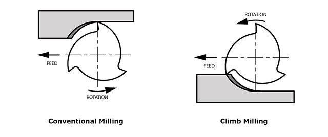 Difference between Conventional Milling and Climb Milling
There are two distinct ways to cut materials when milling, conventional (up) milling and climb (down) milling. The difference between these two techniques is the relationship of the rotation of the cutter to the direction of feed. In conventional milling, the cutter rotates against the direction of the feed while during climb milling, the cutter rotates with the feed. Conventional milling is the traditional approach when cutting because the backlash (Figure 1), the play between the lead screw and the nut in the machine table, is eliminated. Recently, climb milling has been recognized as the preferred way to approach a workpiece due to the fact that more and more machines compensate for backlash or have a backlash eliminator. Below are some key properties for both conventional and climb milling.
Conventional Milling (Figure 2)
• Chip width starts from zero and increases which causes more heat to diffuse into the workpiece and produces work hardening • Tool rubs more at the beginning of the cut causing faster tool wear and decreases tool life • Chips are carried upward by the tooth and fall in front of cutter creating a marred finish and re-cutting of chips • Upwards forces created in horizontal milling tend to lift the workpiece, more intricate and expansive work holdings are needed to lessen the lift created
Climb Milling (Figure 3)
• Chip width starts from maximum and decreases so heat generated will more likely transfer to the chip • Creates cleaner shear plane which causes the tool to rub less and increases tool life • Chips are removed behind the cutter which reduces the chance of re-cutting • Downwards forces in horizontal milling is created that helps hold the workpiece down, less complex work holdings are need when coupled with these forces When to Choose Conventional or Climb Milling Climb milling is generally the best way to machine parts today since it reduces the load from the cutting edge, leaves a better surface finish, and improves tool life. During conventional milling, the cutter tends to dig into the workpiece and may cause the part to be cut out of tolerance. Even though climb milling is the preferred way to machine parts, there are times when conventional milling is the recommended choice. Backlash, which is typically found in older and manual machines, is a huge concern with climb milling. If the machine does not counteract backlash, conventional milling should be implemented. Conventional milling is also suggested for use on casting or forgings or when the part is case hardened since the cut begins under the surface of the material.
Let’s start the work
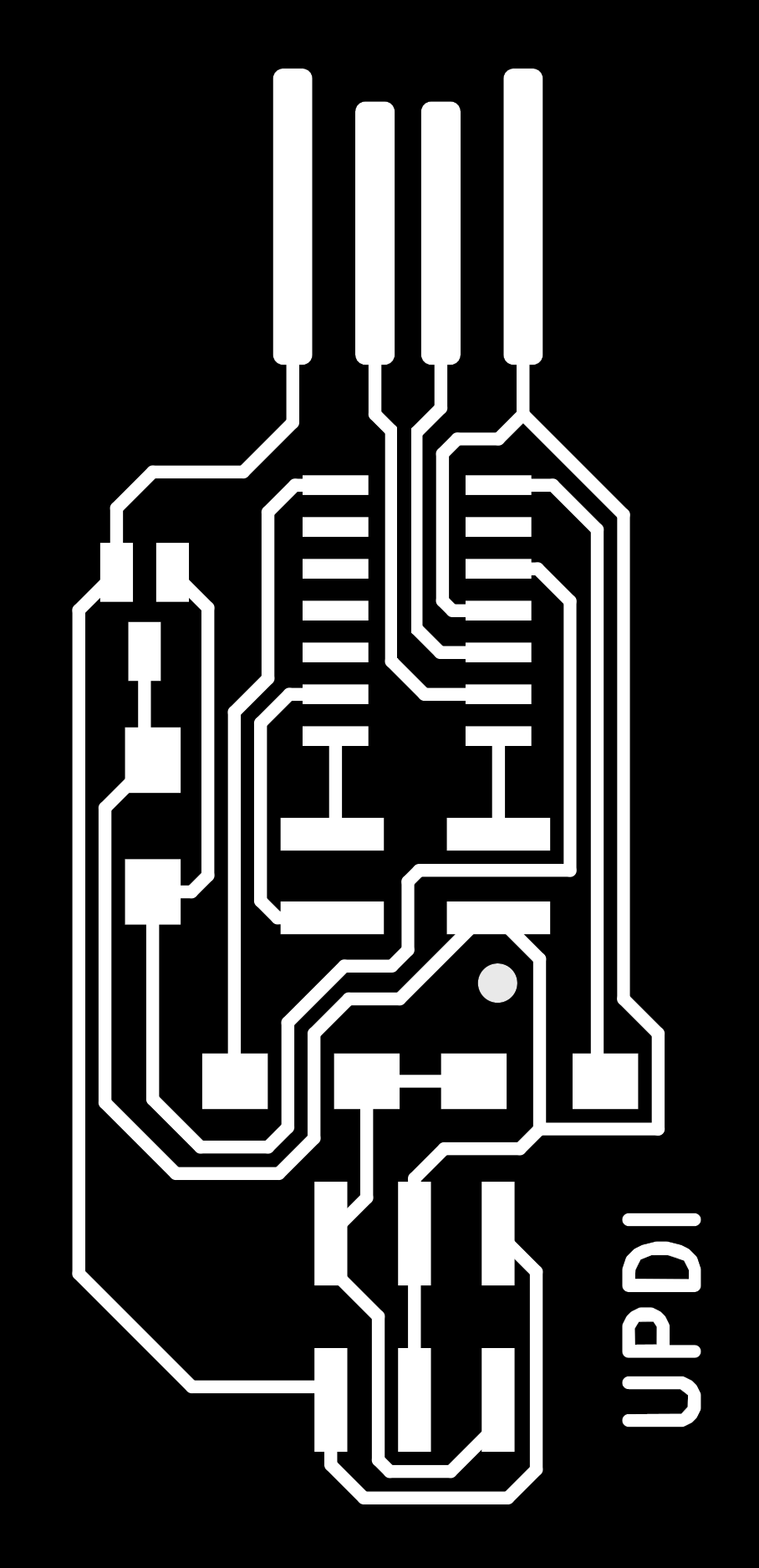
I started the wors in making Programmer UPDI D11C
Individual Assignment
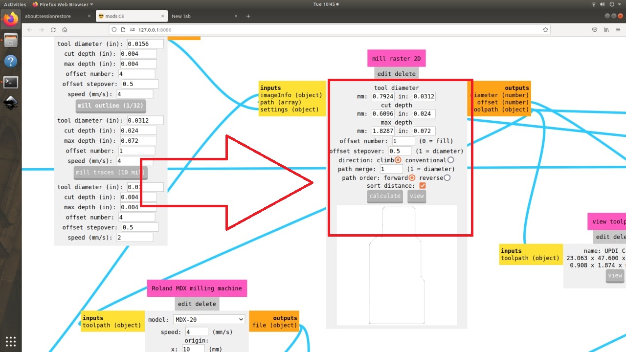
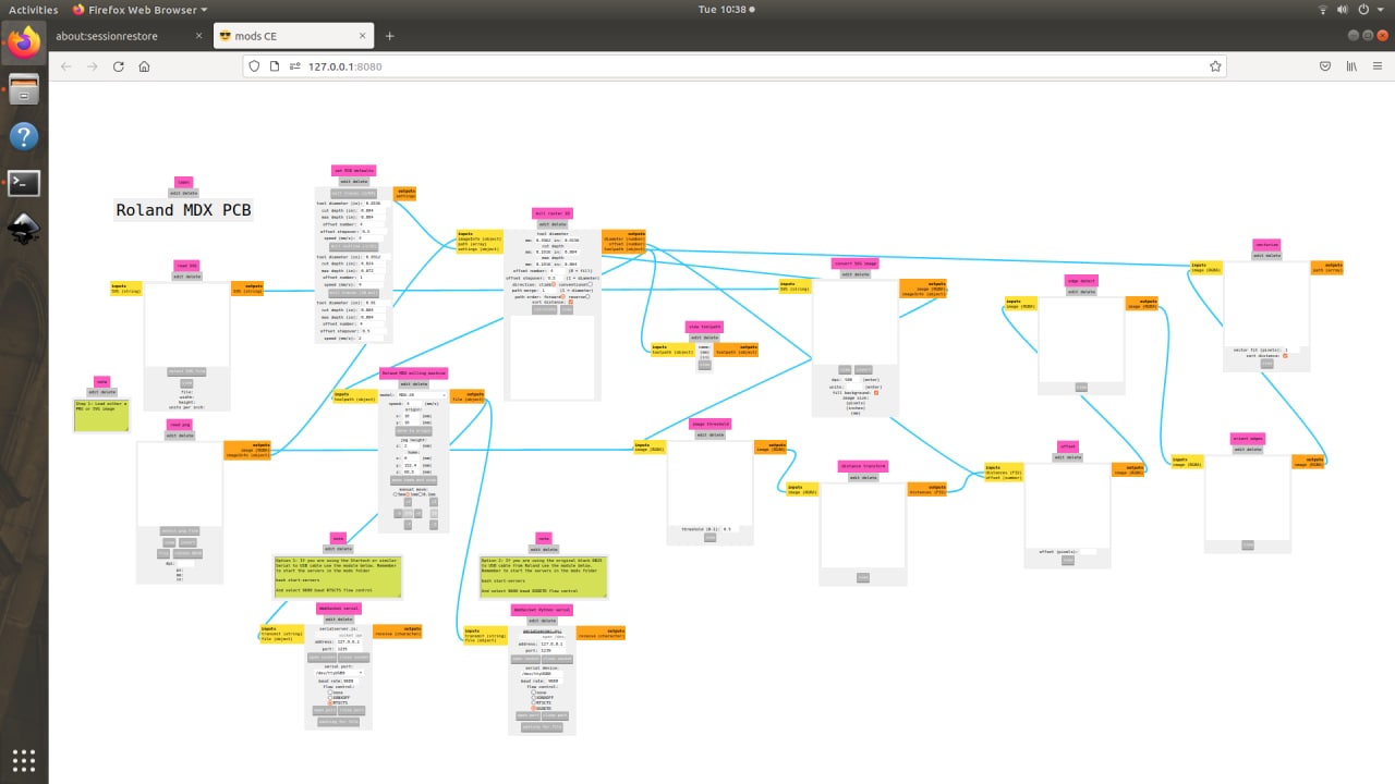
PCB Milling
Then first I studed the milling machine and the using bits, in two types of bits are I used in this work 1/16 and 1/32 in 1/16 bit is used to take a cutting in the PCB and 1/32 bit is used to engrave the PCB

 and I studied the bit fixing in the machine, it is a very risked job because in more chance to the bit will jump to the fixer at any time if it happens suavely the bit is bricked it very costly, so I take more time and I studied that prosses
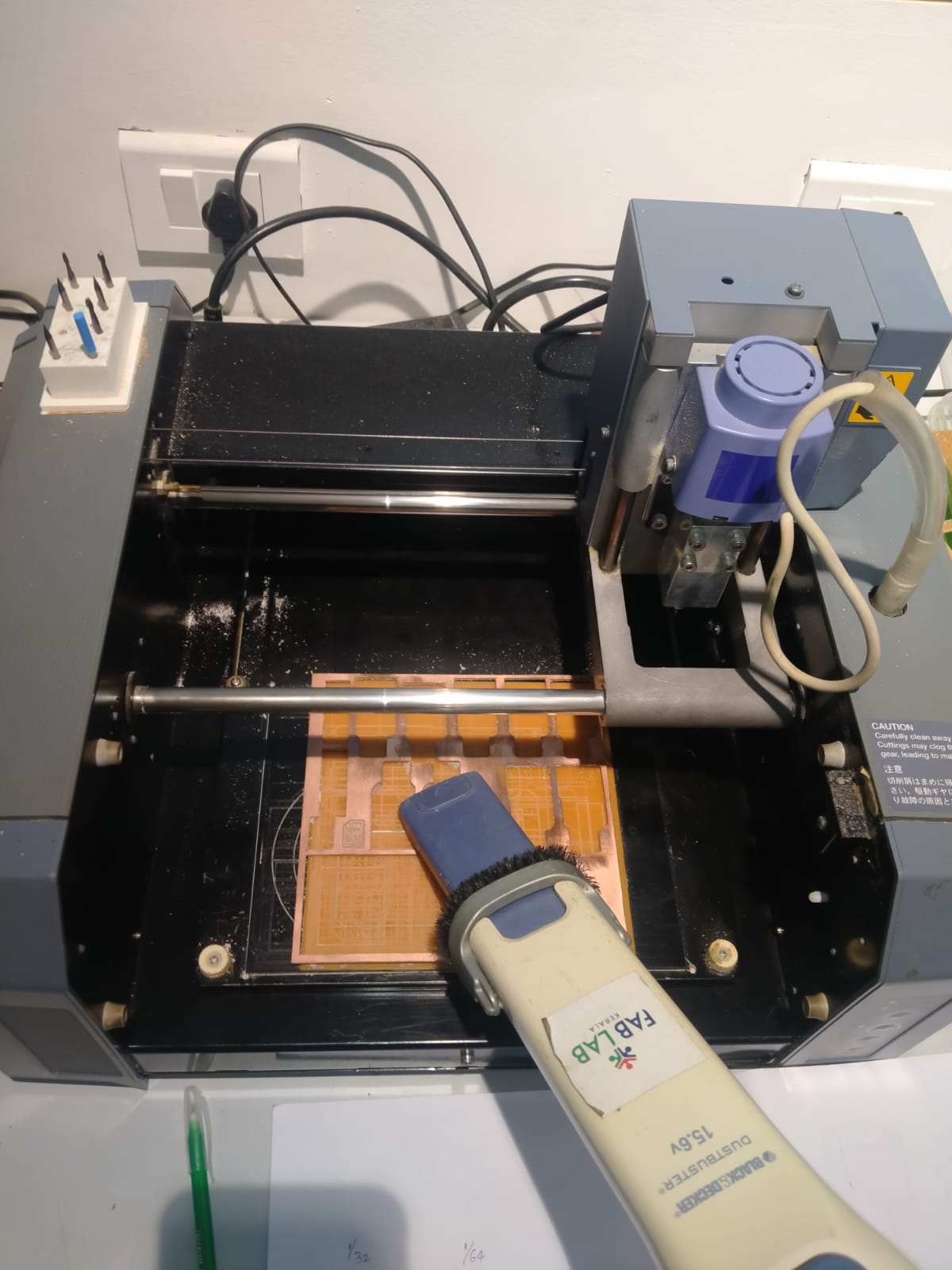
then I started to milling process, I take the coper PCB sheet and I fixed that sheet in the bed if machine using jell tap,
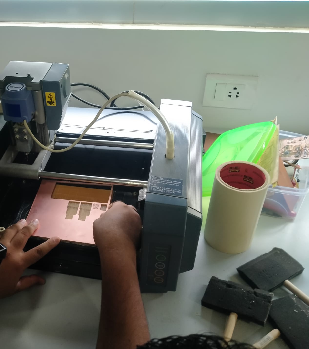
And I arrange the machine in view position then I take and fixed to the the bit if i fixed the 1/32 bit because in first I start te engraving prosses then take that bit
and I Arrenge the origin position using the mode software
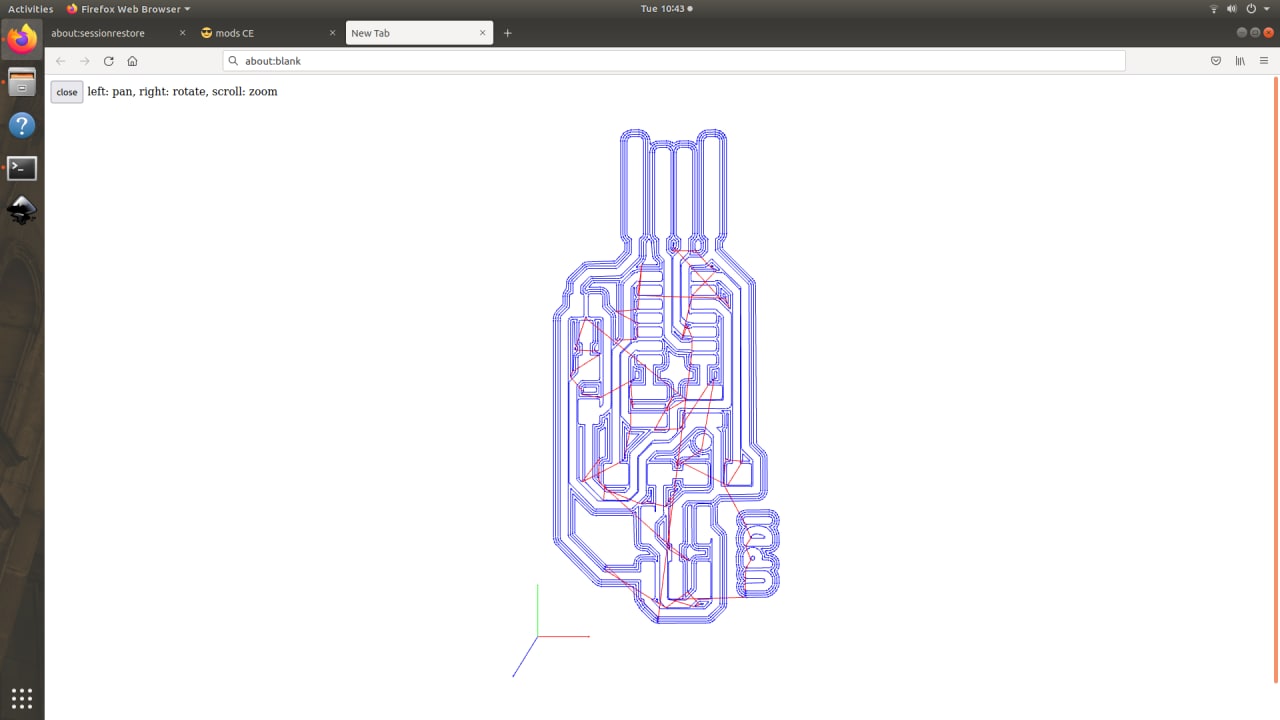
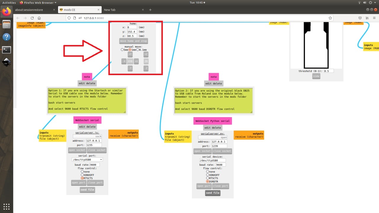 thin I open the engraving file in this software , at that file is already designed because in this weeek assignmend is only mille the PCB so i take the file
 and again fixed the bit in after the set orgin and tited the screw
thin click the calculate button and i click the open stock, then the machine is started the milling prosess
after milling I take the vacuum cleaner and take out the milling dust
 UPDI_Cut.png
then next change the bit in cutting bit 1/32 bit i fixed
UPDI_Cut.png
then next change the bit in cutting bit 1/32 bit i fixed
then open the cutting file on modes and calculate and i click the open stock then i click the start butten
 After te cutting prosses again i use the vacum cleaner then clean the dusts
take the PCB and I cleand very well using san paper
After te cutting prosses again i use the vacum cleaner then clean the dusts
take the PCB and I cleand very well using san paper

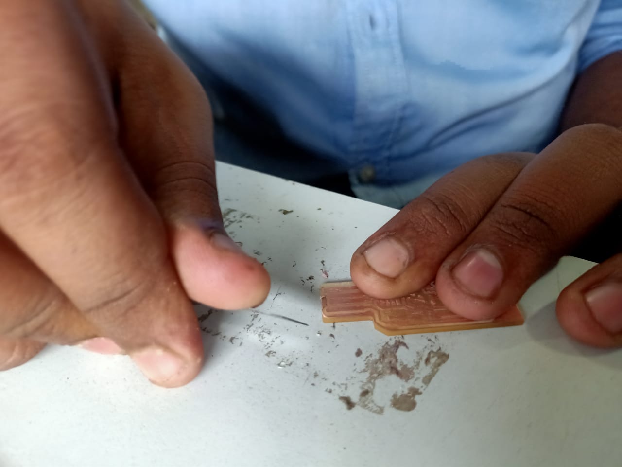 and scrape the edegs using the knife

Soldering
In soldering i am not beginner i have some soldering experiance , so i take the componence in our Fab Lab inventory
so I take the componence
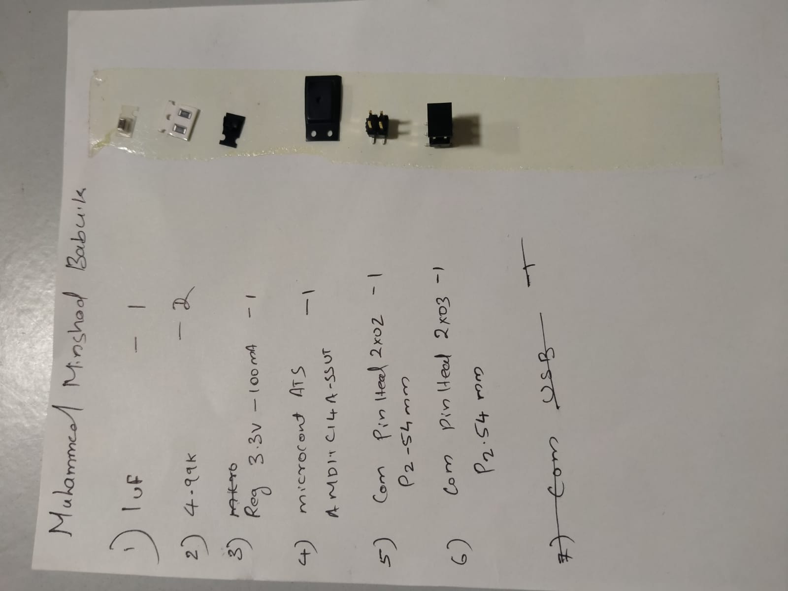
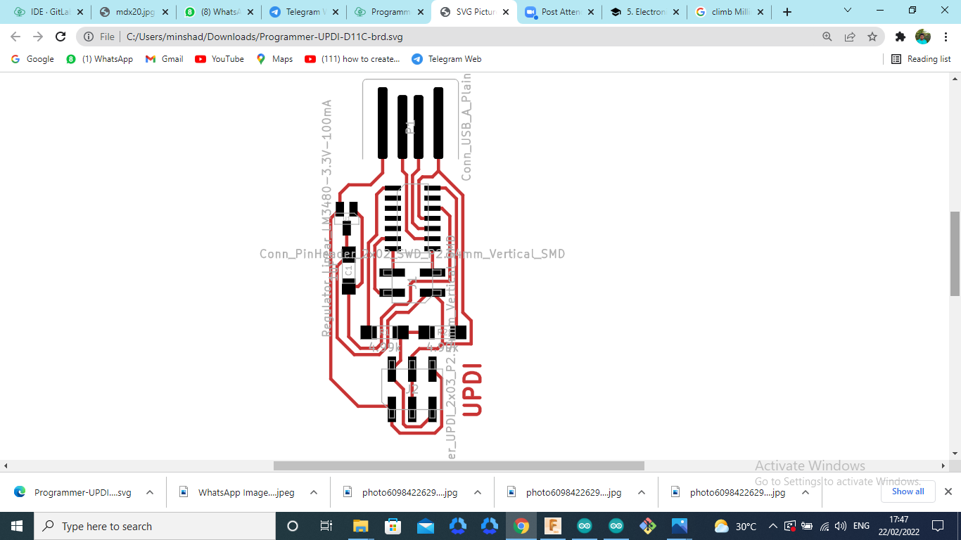
- egulator_Linear_LM3480-3.3V-100mA -1
- Res 4.99k -2
- C1 1uF -1
- ATSAMD11C14A-SSUT -1
- Conn_PinHeader_2x02_SWD_P2.54mm_Vertical_SMD -1
- Conn_PinHeader_UPDI_2x03_P2.54mm_Vertical_SMD -1
so I stick the componace in a page using jell tap because more chance to missing in that compnance
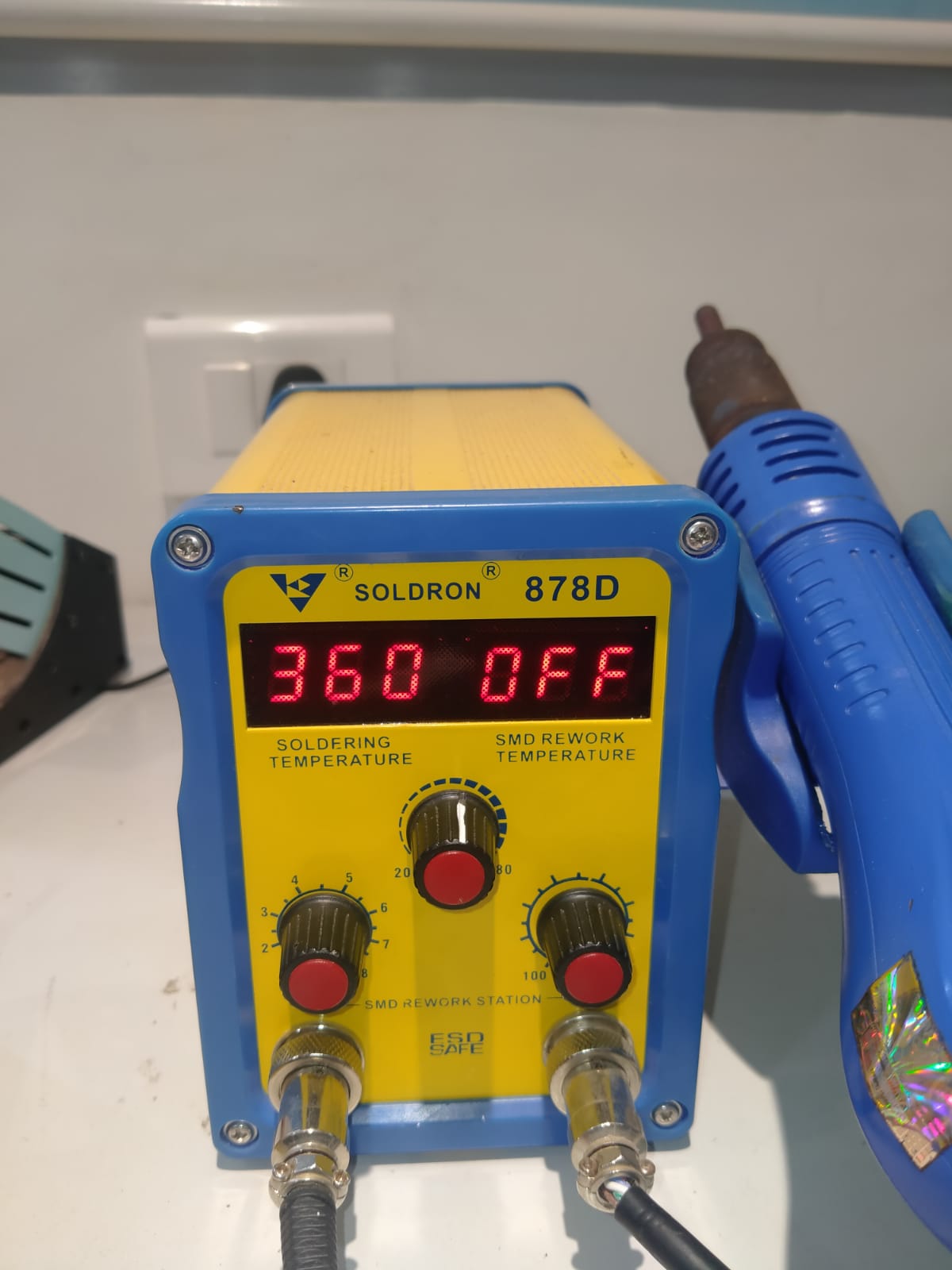
then I start the soldering , in the heat value of the soldering iron is ~ 360
 i take the circut diagram , then started the soldering prosess
 then complete he soldering prosess
chacked the connections in using multimeter
 so the PCB is correct then it ready to programming
Programming
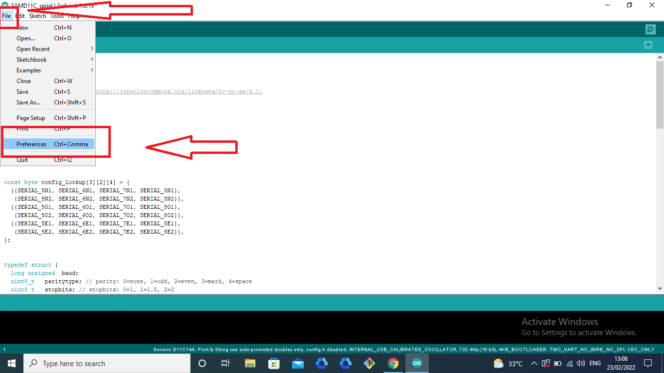
I start the programming process ,I am not begener in programming I have some experiance in the programming,so i started that prosses, first I downlode arduino software and install it,
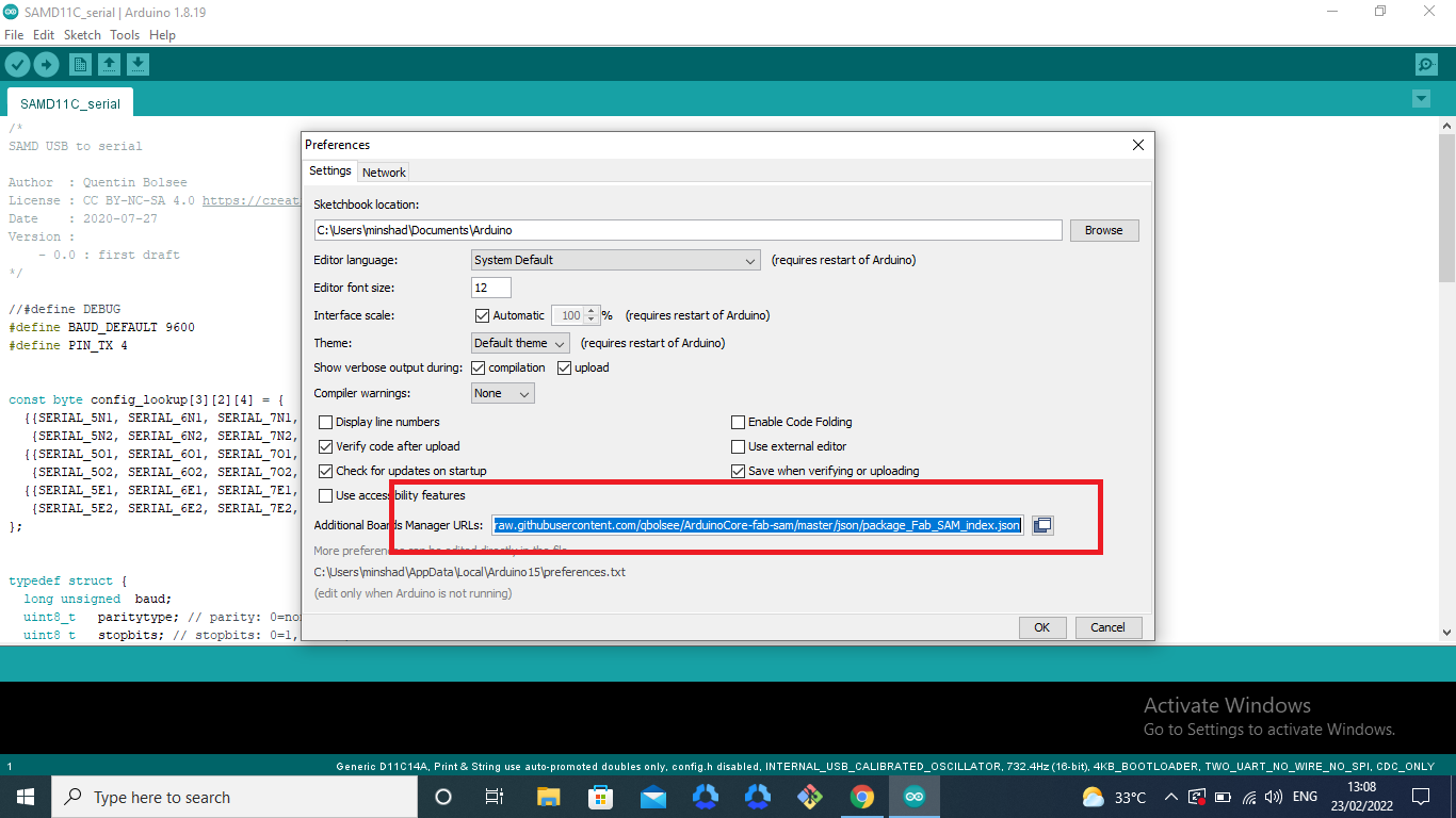
then I go to - THIS website, in this website have the full details for the UPDI D11C ,so opend it
then I take to copy this link and go to arduion software and paste and upload THIS in the preference
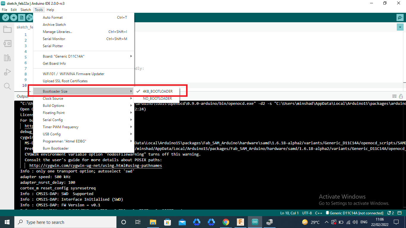
next I go to manage boards and serch that boad for fab ,then got it.

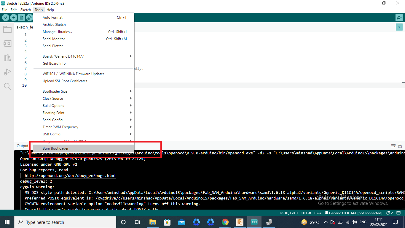
then take that boad and connect the my programmer in to the SAMD11 master programer and take to compair and upload that program

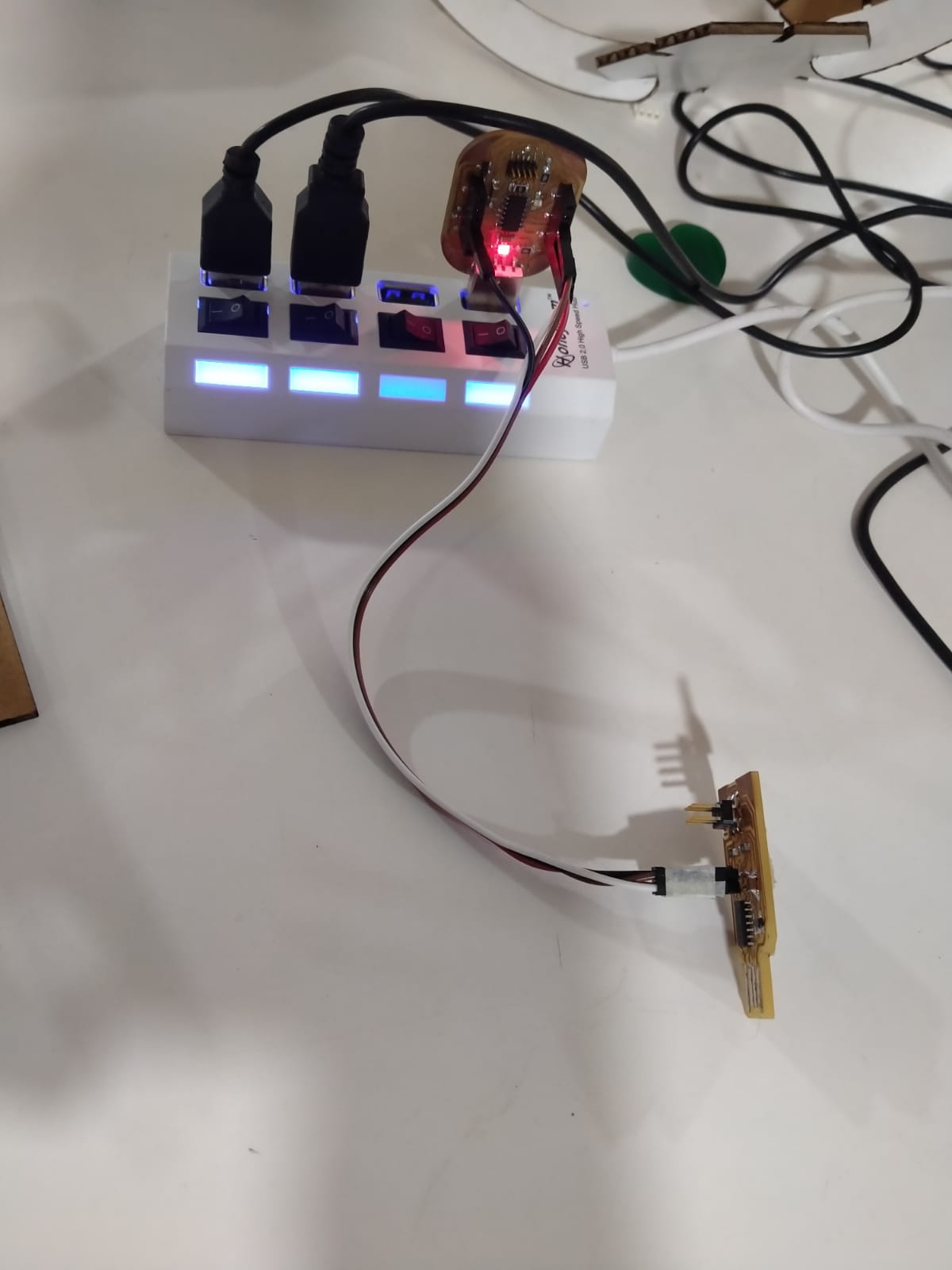 got it for the notification in arduino for uploding is done
next go to this link and cloun the git bash at thet time got the programm
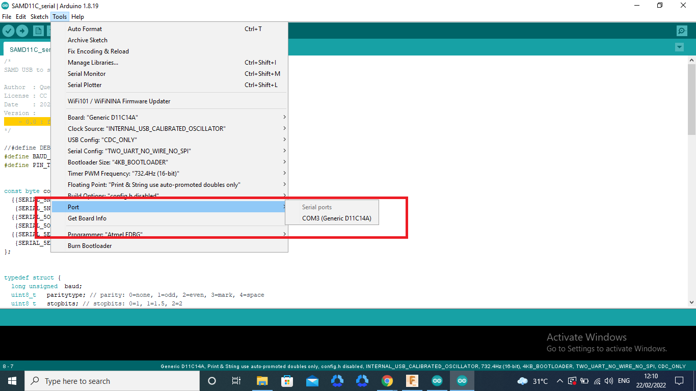
then connect my programer and select the com port and upload the program, that prosess is sucssesfuly done
All Files Download here Download