4. Computer Controlled Cutting
Objectives
Design, laser cut, and document a parametric press-fit construction kit, which can be assembled in multiple ways. Account for the laser-cutter kerf.
Cut something on the vinyl-cutter.
Group Assignment Group Assignment page
Characterize the laser cutter’s focus, power, speed, rate, kerf, and joint clearance.
Document the work.
The Fourth week’s class of my fab academy life took place and the professor Neil class started as usual,this week assignmend as khown as Computer Controlled cutting thay introduce using vinyl cutting and laser cuttingand to make modular models.
Group Assigment
- Kerf
During any cutting process, the cutting tool causes some excess material to be lost in addition to the specified design. When a laser cuts a material, its path burns off some material, known as the kerf of a laser cutter.
- Cutting Parameters used
We created a file as shown below and adjusted the settings in the job control to find the best cutting parameters for each material, maintaining power constant and speed ranging from 100cm/sec to 20cm/sec for engraving and 1cm/sec to.2cm/sec for cutting *the values may change as per the meterials used.
Acrylic
Cutting Power=100 Engraving Power=70 Cutting Speed=0.4cm/sec Engraving Speed=60cm/sec Number of passes=1 Frequency=1000
Wood
Cutting Power=100 Engraving Power=70 Cutting Speed=0.2cm/sec Engraving Speed=60cm/sec Number of passes=1 Frequency=1000
Cardbord
Cutting Power=100 Engraving Power=70 Cutting Speed=1cm/sec Engraving Speed=60cm/sec Number of passes=1 Frequency=1000
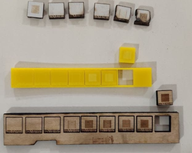
Test and Calculation
We measured the inner diameter of the square hole within the cutout component using a digital vernier, then the exterior dimension of the removed piece.

Now we can determined kerf by subtracting the inner from the outer dimension and then dividing by two.
Acrylic
20.20-19.87= 0.33 kerf=0.33/2 kerf=0.165
Wood
20.41-19.8= 0.61 kerf=0.61/2 kerf=0.305
Cardbord
20.35-19.84= 0.51 kerf=0.51/2 kerf=0.255
Press fit

Vinyl Cutter
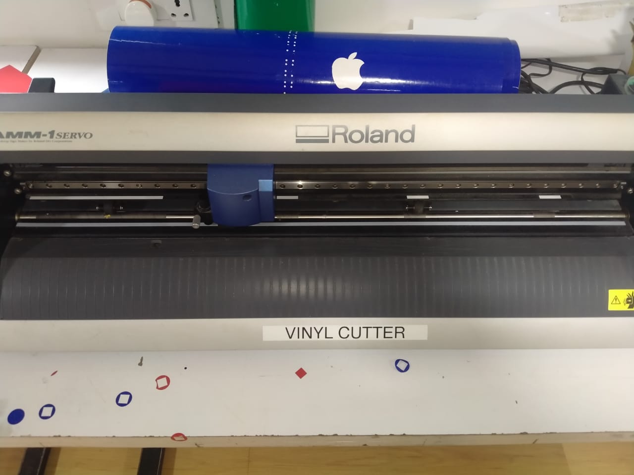
A vinyl cutter is an entry level machine for making signs. Computer designed vector files with patterns and letters are directly cut on the roll of vinyl which is mounted and fed into the vinyl cutter through USB or serial cable. Vinyl cutters are mainly used to make signs, banners and advertisements. Advertisements seen on automobiles and vans are often made with vinyl cut letters. While these machines were designed for cutting vinyl, they can also cut through computer and specialty papers, as well as thicker items like thin sheets of magnet.
our fab’s vinyl cutter is Roland

stups of vinyl cutting - Draw 2D image Pichtue using 2d software
-
Downlode that file in PNG
-
Transfer that file in CBA modes
-
Calculate and set force of vinyl cutting machine
-
Switch ON vinyl cutter mechin and fix to the meterial roll
-
Set the orgin in vinyl cutter
-
Click the start butten
-
Take the result
Draw 2D image using 2d softwares
I done my 2D image design using inkscape software becours inkscape very easy to design in bigners so that known I used it .
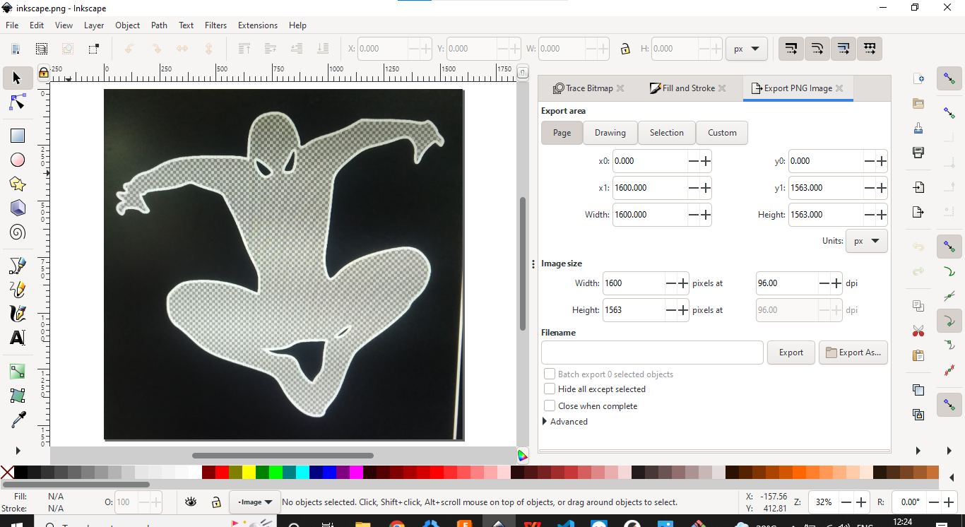

I designed that pictuer in not fully i drsign ,i downlode thais pctuer and edit to only take that pictuer
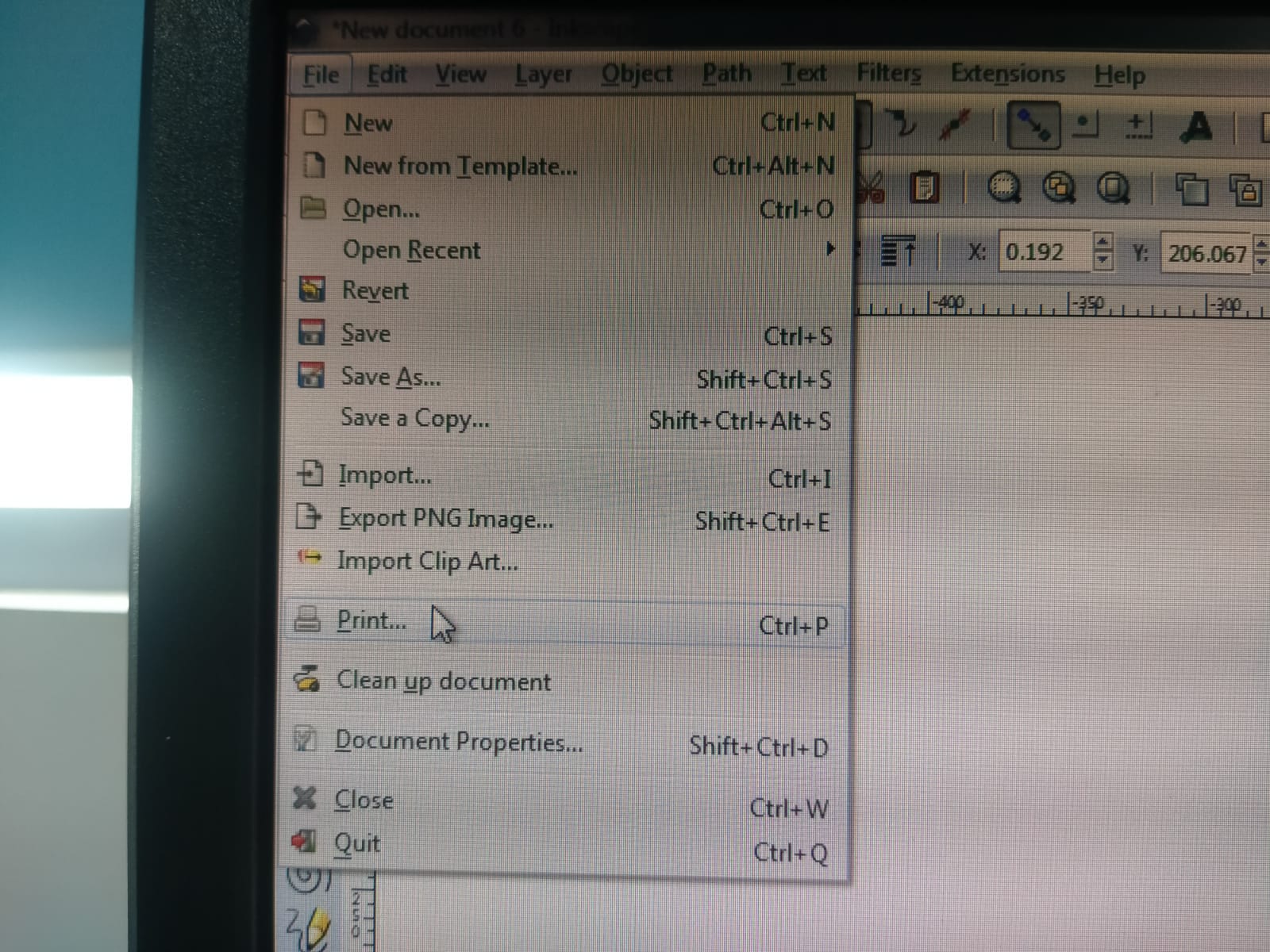
Downlode file in png format
At last I saved that pictuer in png format
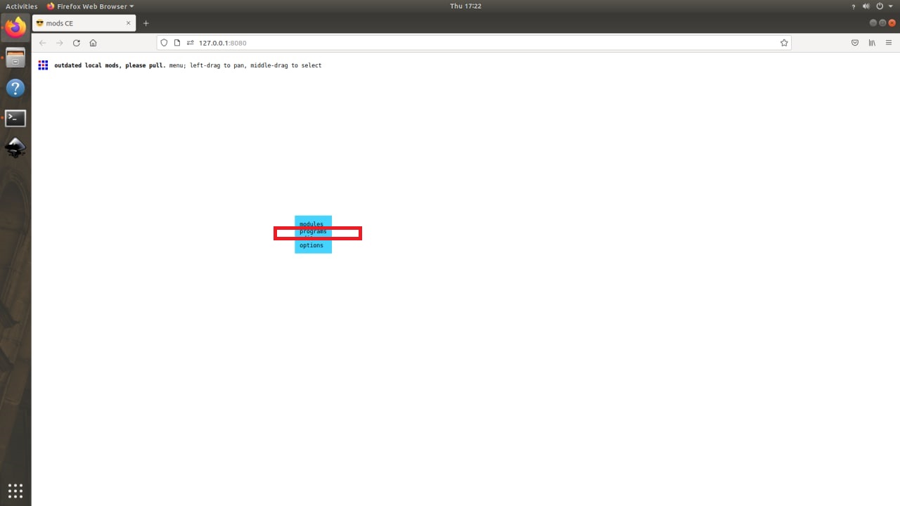
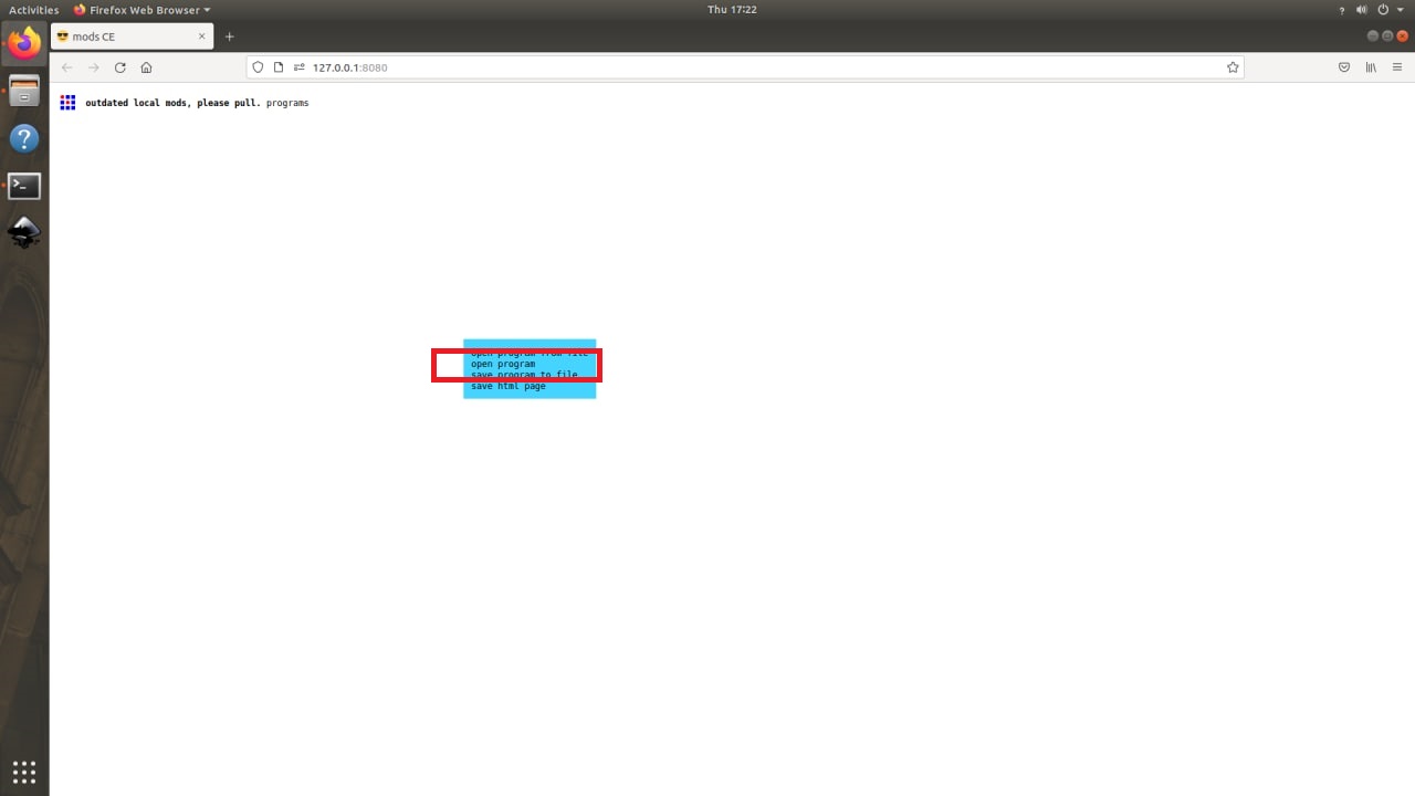
Transfer that file in mods
In modes software only install in our lab’s computer i transfer that file using send anywer website.
Then I opend thay pictuer in computer files


Calculate and set force of vinyl cutting mechine
 I calculate thae force using this so modes in on screen
Switch ON vinyl cutter mechin and fix to the meterial roll
The company that makes our lab’s vinyl cutting machine is Rolend, and it runs on a 24V 2.8A 67.2W AC current. I turn on the machine, and to fix the meterial roll, I used vinyl sticker, which is normally used in sticker works on cars, bikes, and other vehicles. Anyway, I fix that roll, and in the foxing time, make sure to notice that there are only a few fixing points, and pull the fixing lever.
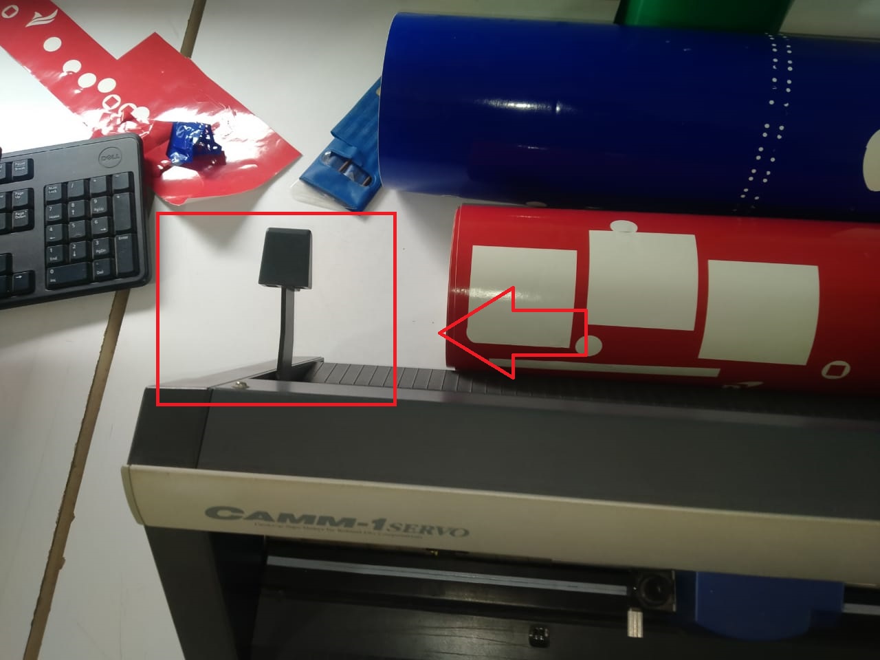
Set the orgin in vinyl cutter
Orgin is a known as starting point in theb rolend company calling is orgin that only ,in orgin seting take four switch to take left, right ,back andfront to switch and i take one point ant to fix it
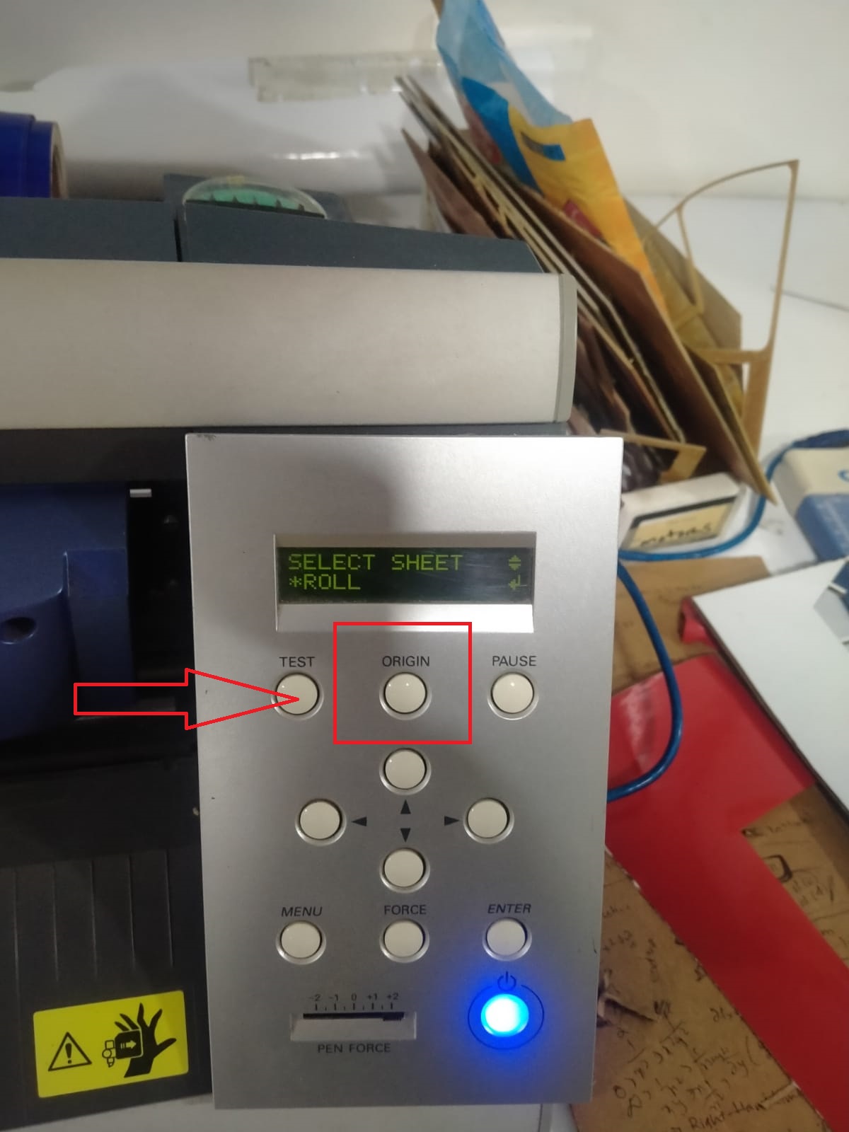
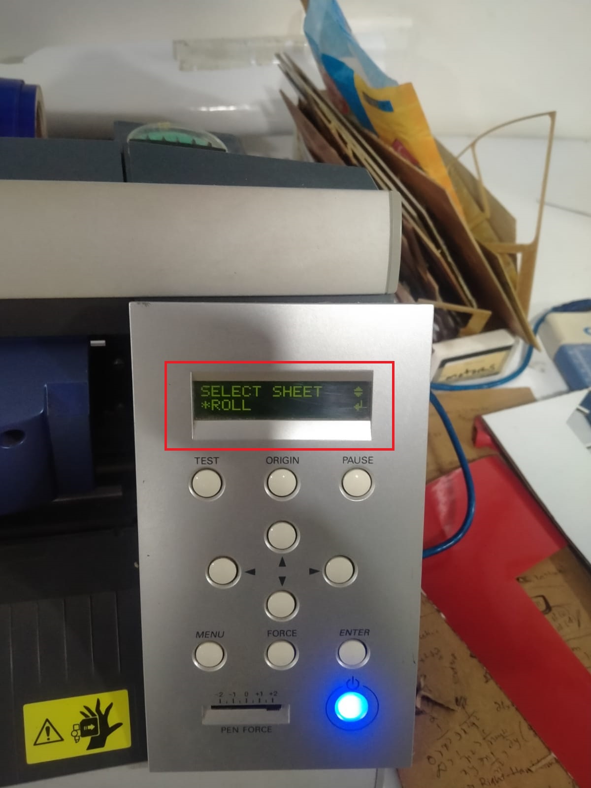
Click the start butten
I turn on the machine’s control knob and select the file tranfer software from the menu on the screen. I press the button and begin cutting in my photograph.
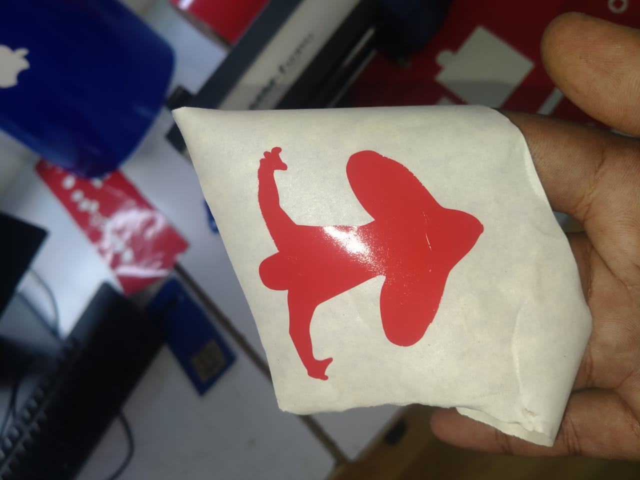
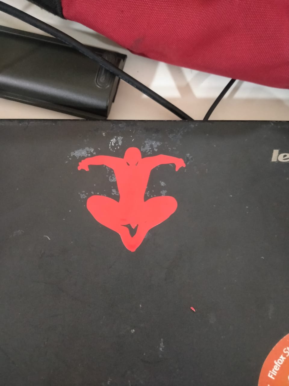
Take the result
I can obtain my outcome, and then I take out the external portion and take the masking tap and stick it on the sticker, then I take my output, and then I stick the project in my laptop.

Laser Cutting
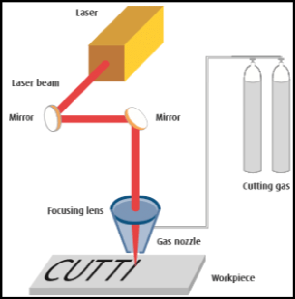
Laser Cutting uses a high-power laser which is directed through optics and computer numerical control (CNC) to direct the beam or material. Typically, the process uses a motion control system to follow a CNC or G-code of the pattern that is to be cut onto the material. The focused laser beam burns, melts, vaporises or is blown away by a jet of gas to leave a high-quality surface finished edge.
The laser beam is created by the stimulation of lasing materials through electrical discharges or lamps inside a closed container. The lasing material is amplified by being reflected internally via a partial mirror until its energy is enough for it to escape as a stream of coherent monochromatic light. This light is focused at the work area by mirrors or fibre optics that direct the beam through a lens which intensifies it.
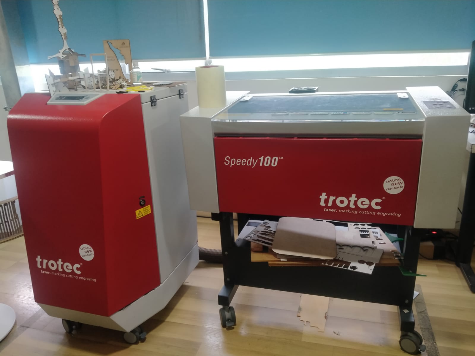
In our fab lab using this laser machine
I begin my design process with Fusion 360. FUSION 360 is a good 3d design software, therefore I use it to create a variety of products, including some humorous ones. Because I’m new to laser cutting, I’m spending more time studying. As a result, I’m designing more goods and using the laser cutter’s output..
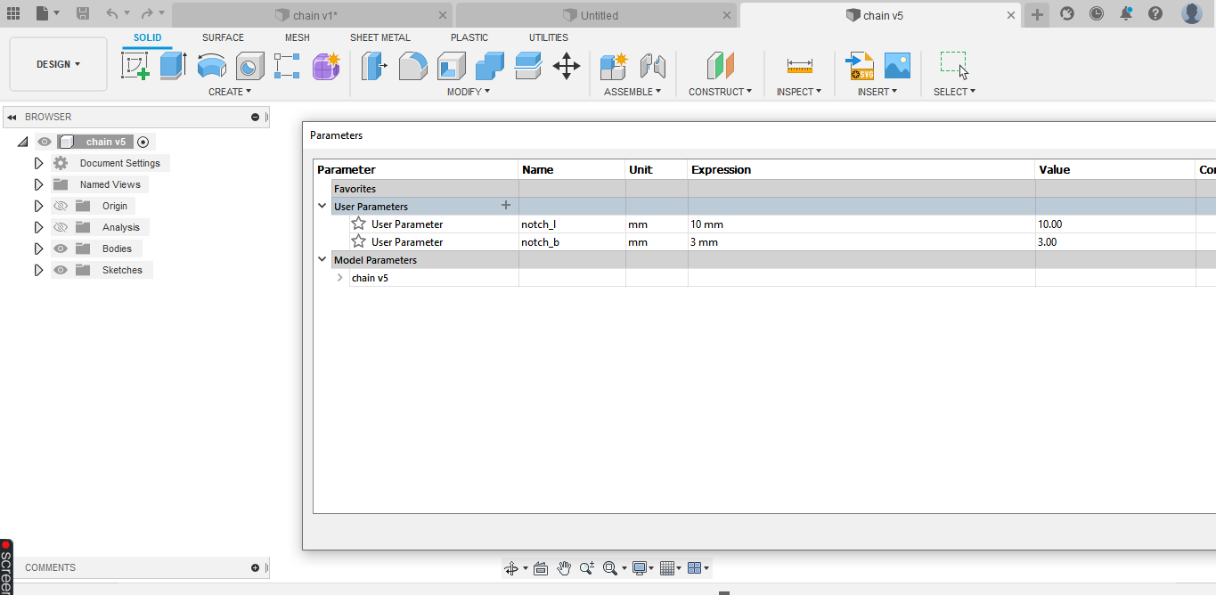
 arametric design
After searching about models of the parametric construction kit, I made an idea about the design.
arametric design
After searching about models of the parametric construction kit, I made an idea about the design.
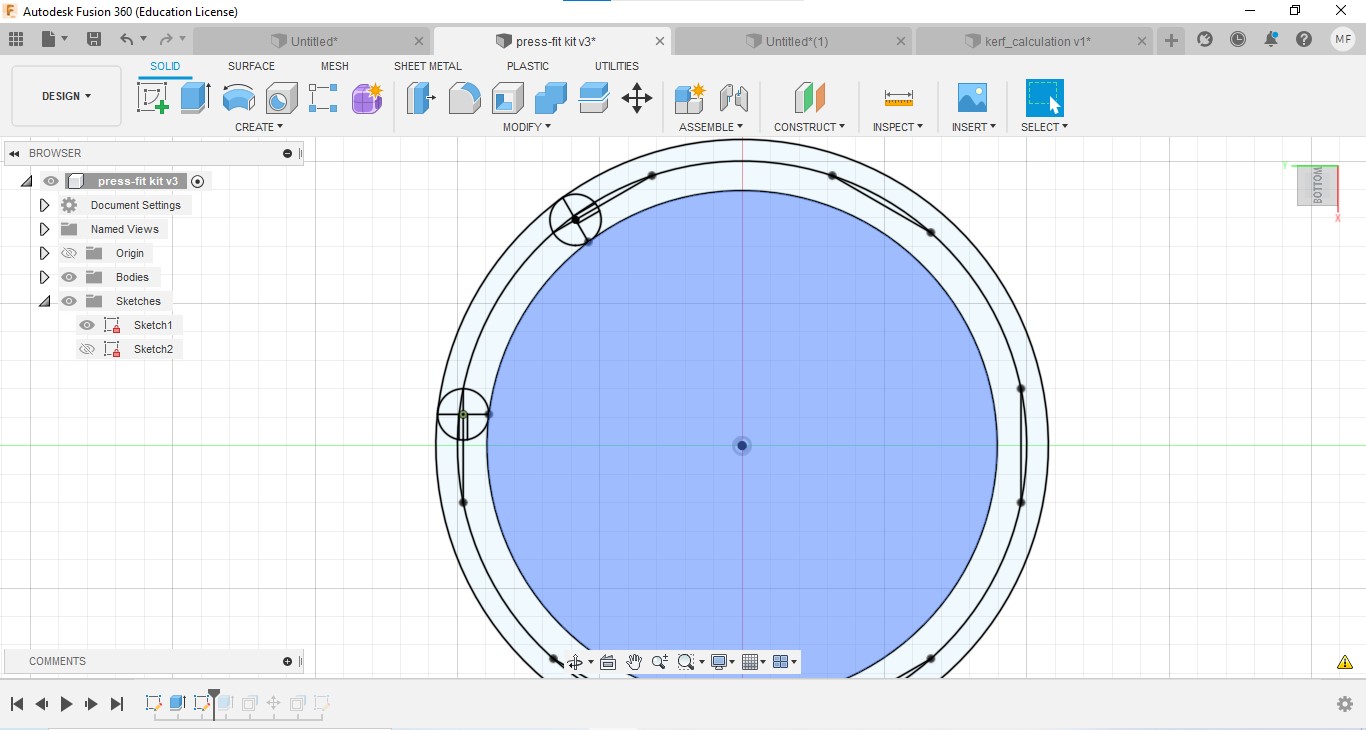
Then I started drawing in Fusion 360.
Instead of normal drawing, here I set some parametric values(Thickness, noch length, noch breadth, etc.)
For this, select ‘Modify’→ ‘Change Parameters’
We can add new parameters by clicking on the ‘+’ icon near ‘User parameters’.
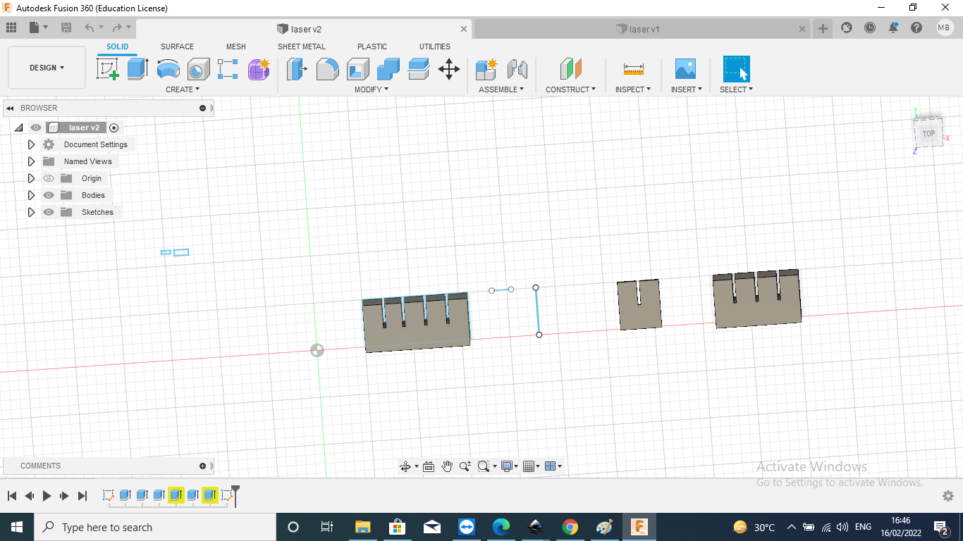 In using to press fit method I designed the parametric designs ,so this is the perametric values in the usage of parametric is in chainging values is easly, so I do it.
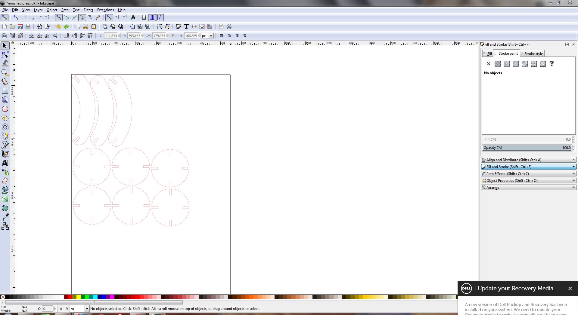
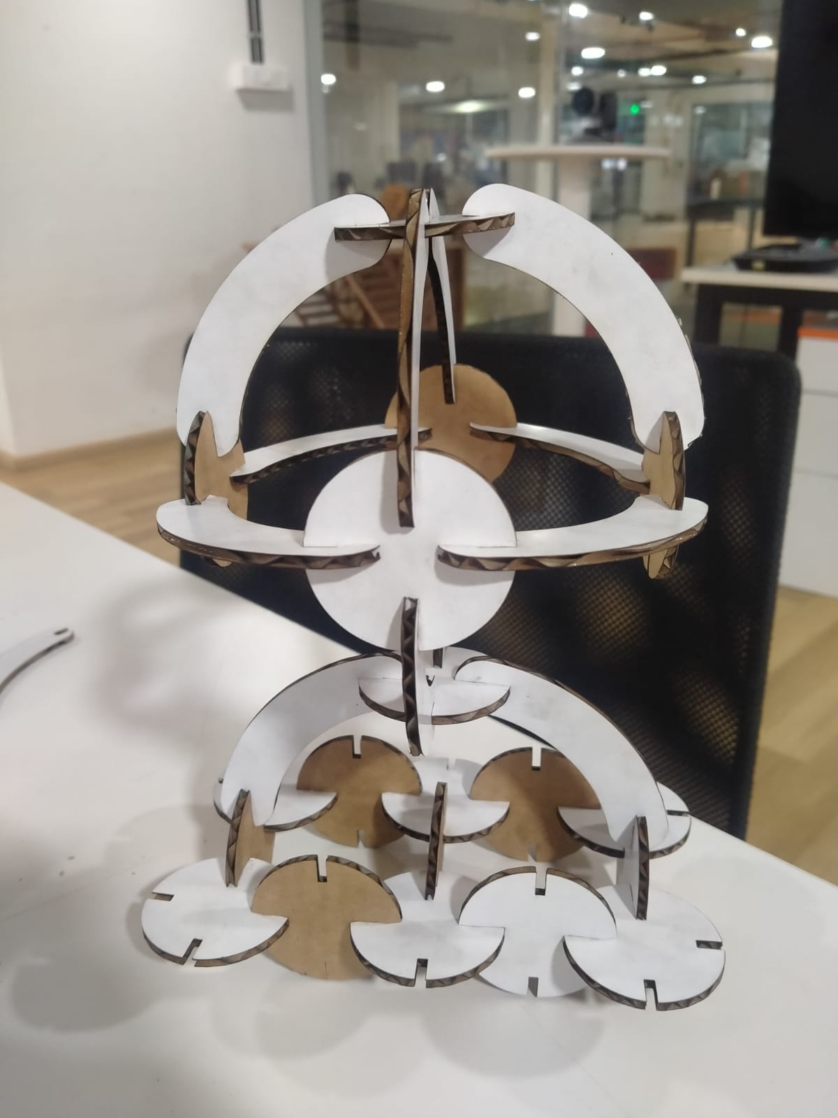
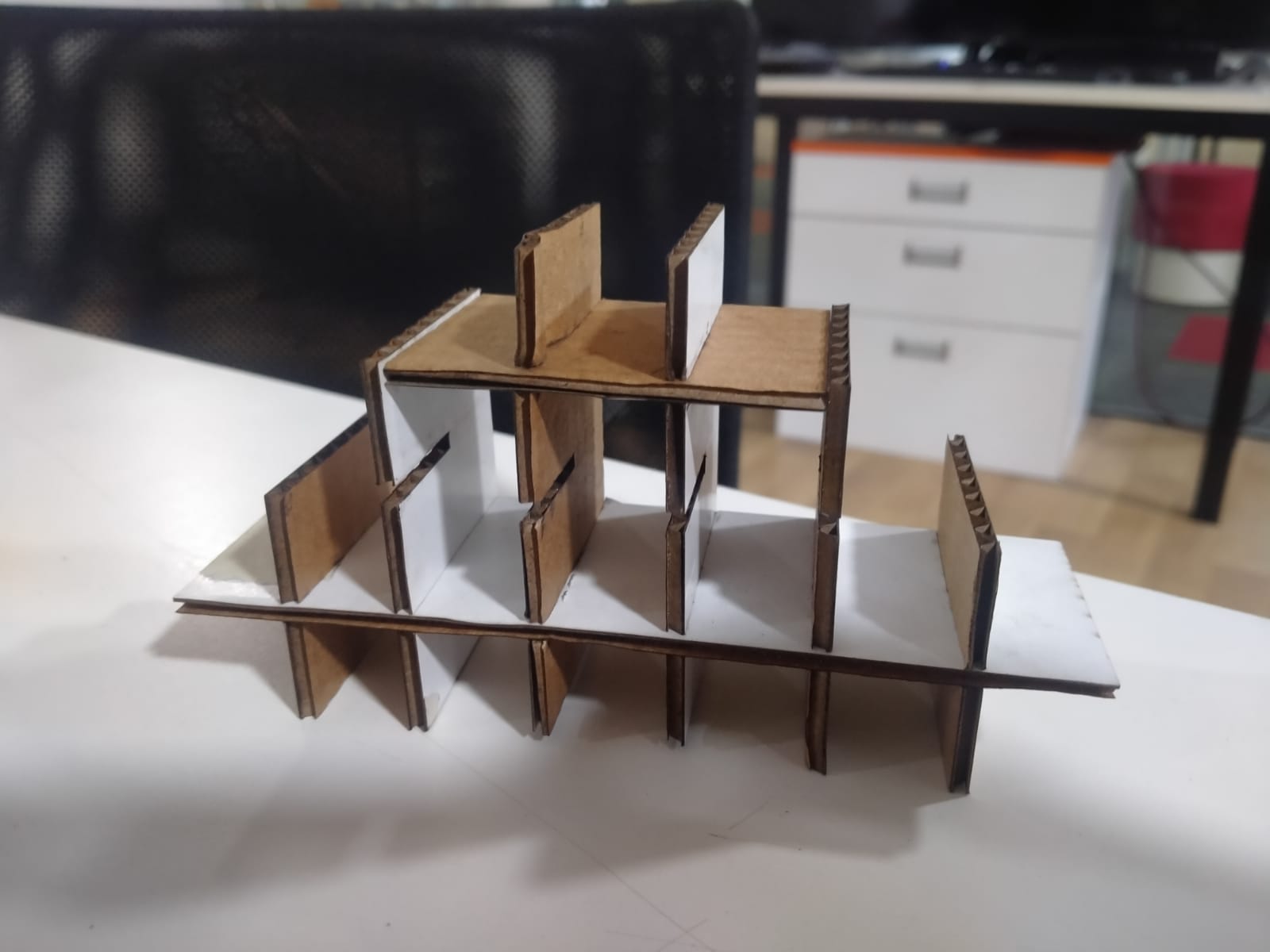
This is my design in this design is a small designs
So I used send anywere to transmit those files to our lab’s computer, and then I opened that file in inkscap and edited it with the fill and strock the border fill with red colour, and then I printed it.
Finally, I opened the Trotec job controler programme, which allows me to control the laser cutting machine, so I opened that picture in it.

Then, depending on the materials, I adjust the speed and power, therefore I used the carboad to do so.
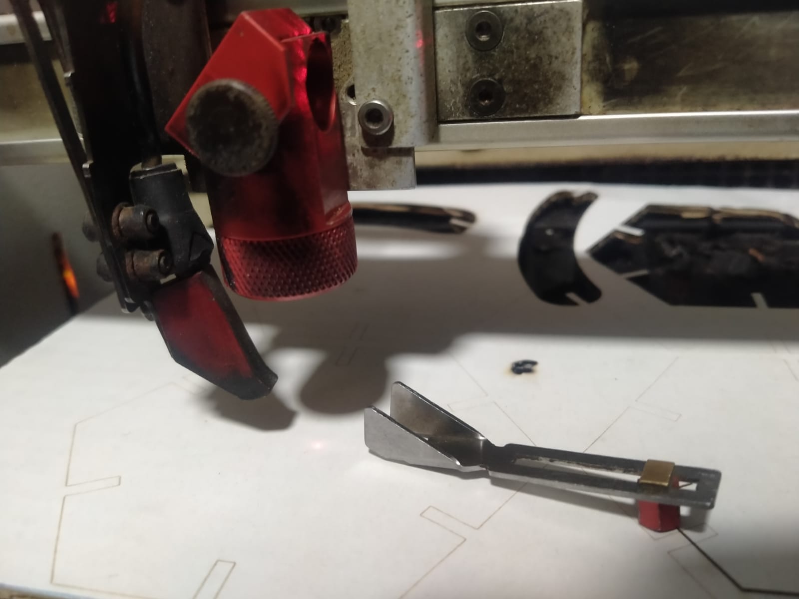
After that, I’m ready to start laser cutting procedures. First, I choose the material for the laser bed, then I focus the laser in this procedure using a fcusing tool in this machine.
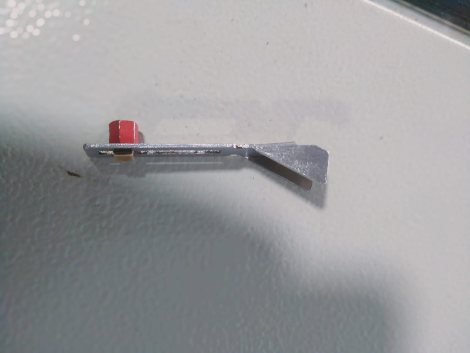
I use the focusing tool to focus the laser, and the laser in this bed moves up and down. At that point, the focusing tool will think out how to remove the material, so I take out in the up position.

In using this to button the bed can take up or down
and focusing
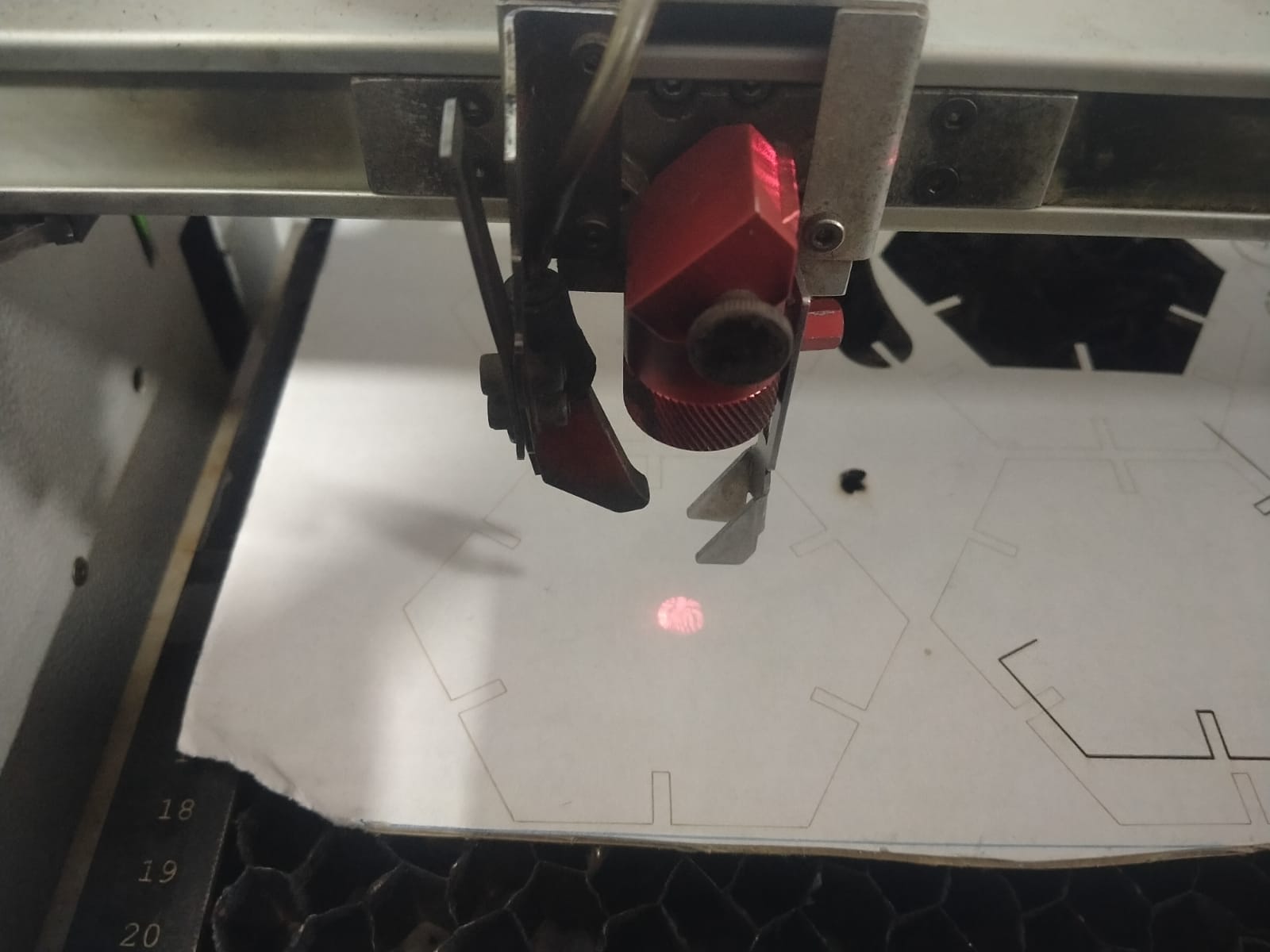
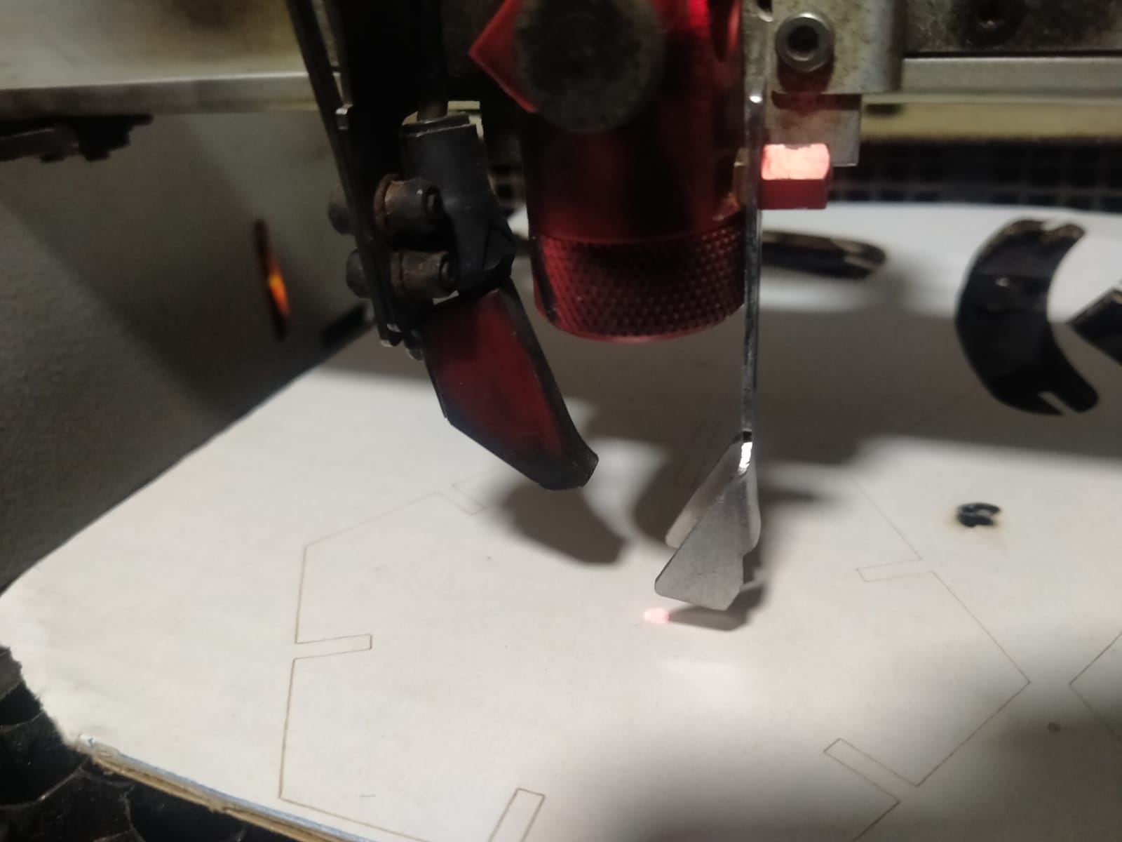
I got my focus ready and started cutting.
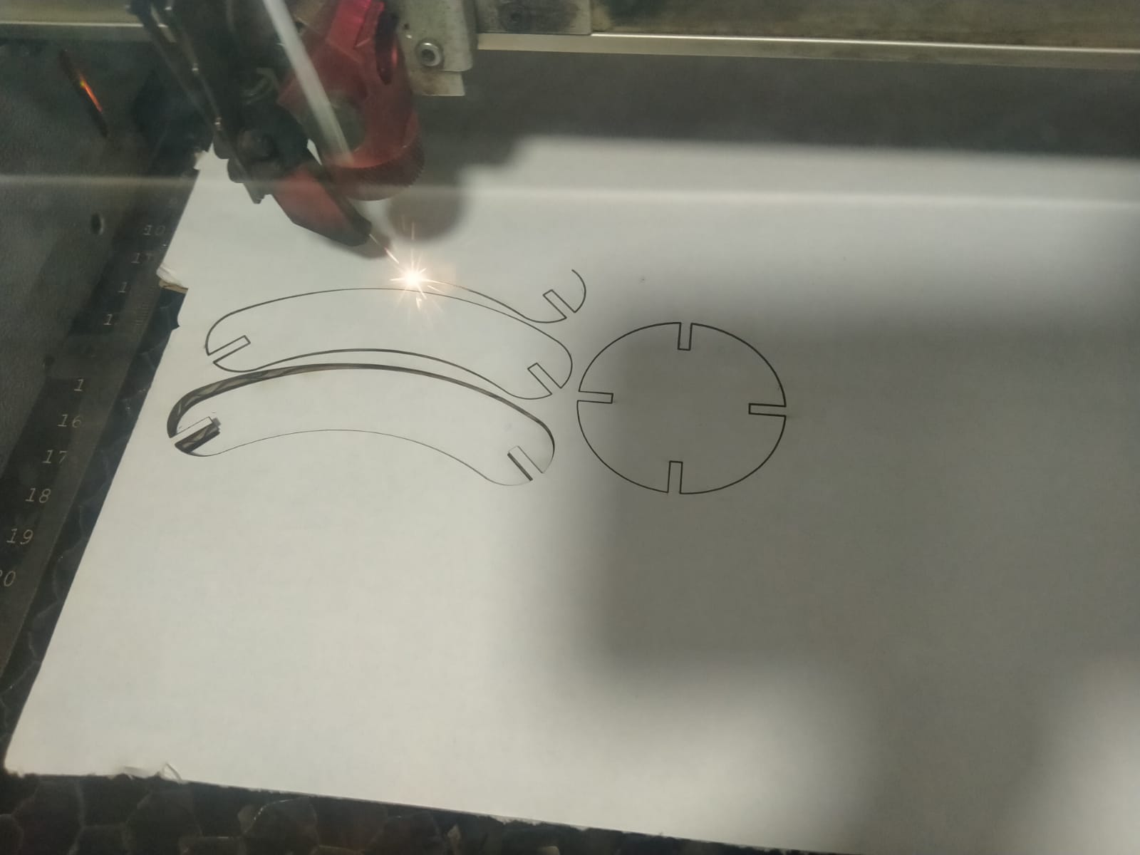
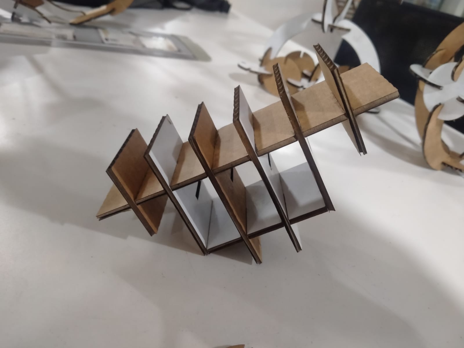
Finally, I cut the material and joined it together, and here is the end result.


I do some laser cutting and engraving in acrilic


In this project i find and cut the curf

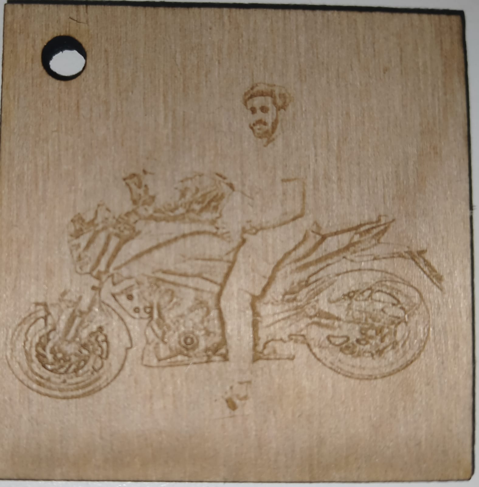
Then I do some laser Engraving in acrilic and wood
All Files Download hereDownload