Week 16 Wildcard Week

Assignments:

Assignment:
    • Design and produce something with a digital fabrication process (incorporating computer-aided design and manufacturing) not covered in another assignment, documenting the requirements that your assignment meets, and including everything necessary to reproduce it.

Learning outcomes:

    • Demonstrate workflows used in the chosen process.
    • Select and apply suitable materials and processes to do your assignment..

Assignmnets

This week was really fun as we were allowed to go wild but with a certain budget :)
So firstly I chose to explore writing g code to understand more how the machines works and kinds of dive in computer vision/machine learning process.
Thanks to my instructors for availing valuable resources, especially this link . It is like a must go website for learning g code. Then thanks to my colleague who provided me with writing the g code handbook which explains deeply and more technically. So kind of group assignment we both explored together and wrote our first code from scratch.
image
image

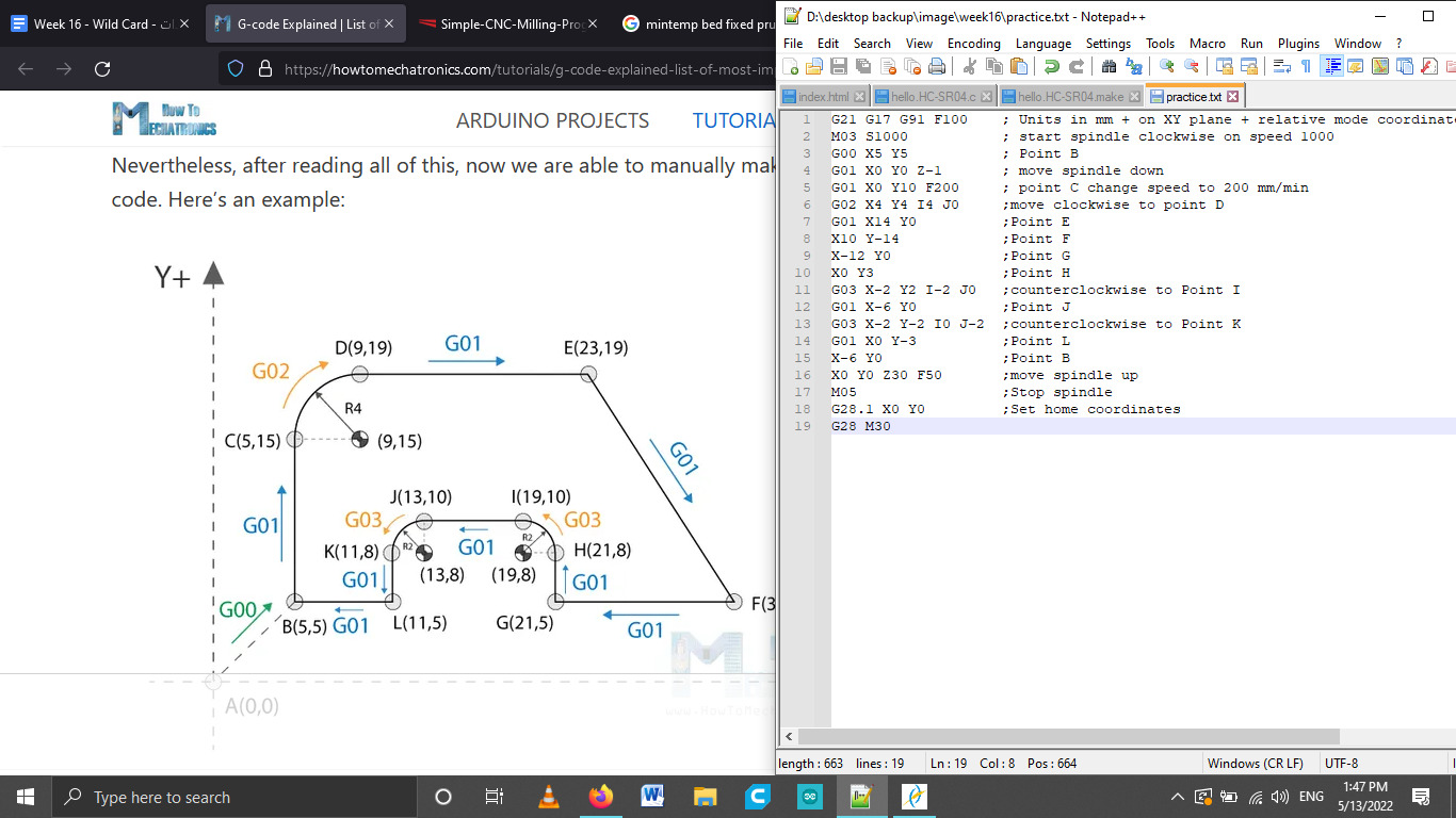
Here is my individual practice according to the resource provided.
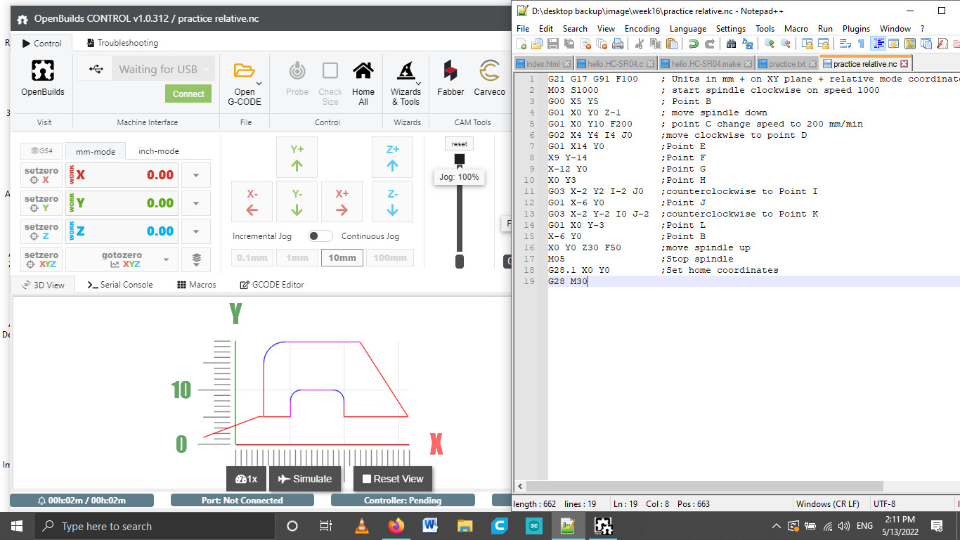
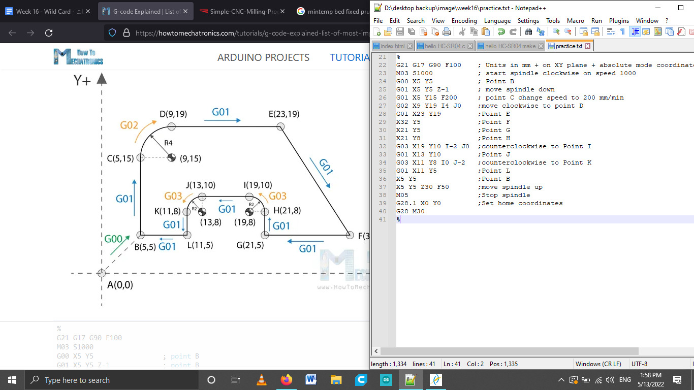
The pictures describes writing of gcode in 2 different modes,

    1. The picture above: code written in absolute mode using command G90 which means that the following code (coordinates) will be written according to the positioning of the tool is always from the absolute point or zero.
    2. The picture below: relative mode G91 command. Which indicates to the machine that the coordinates will be positioning of the tool relative to the last point.

Example: Point Es coordinate is 23,19 so in G90 its written as it is. Because it is relative to the Zero point.
In G91 it is written relative to the last point D the tool will move 14 in X axis and 0 in Y axis.

image
Writing of G-code book

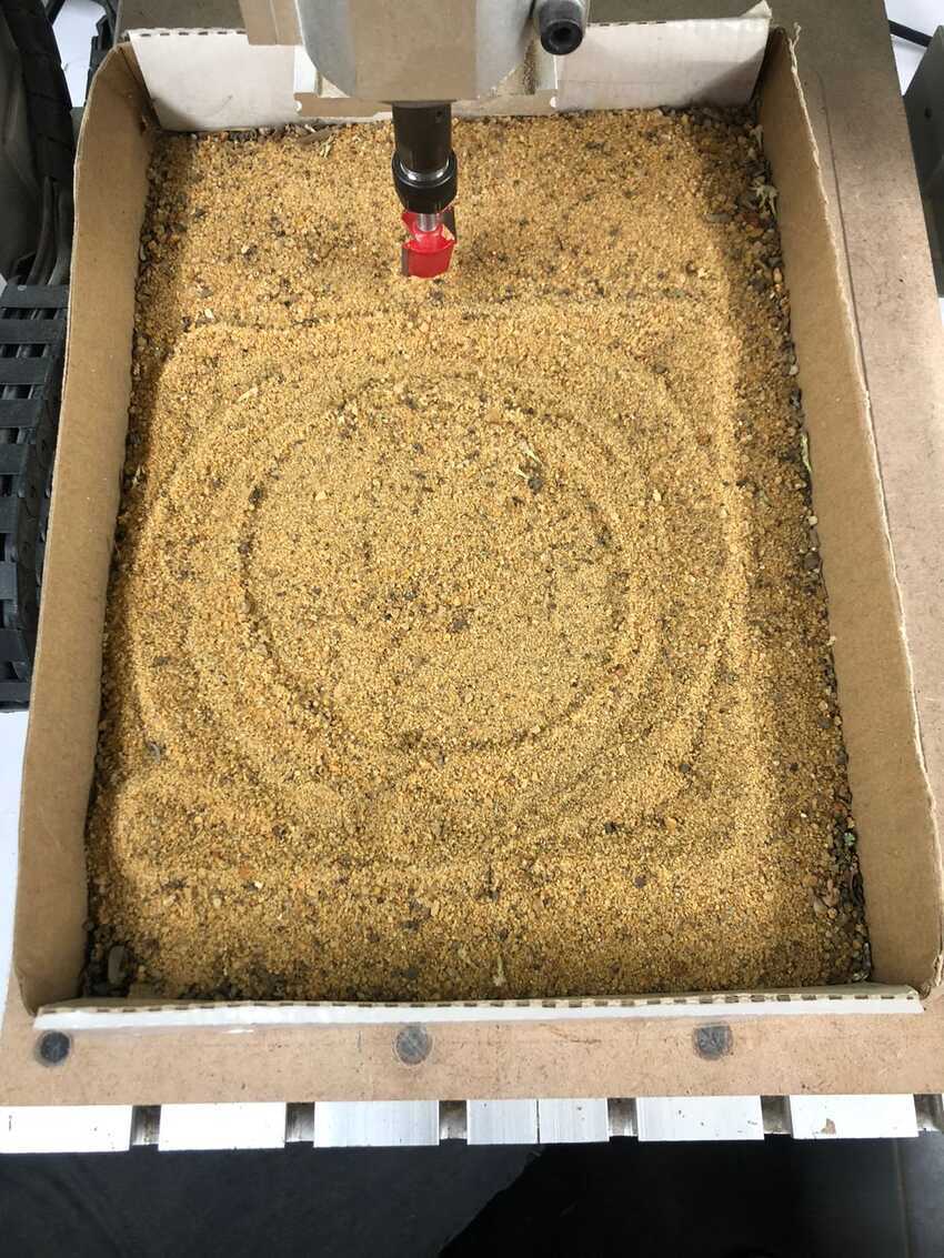
Then after reading the book we both combined our code together to test it on our milling machine china router and without operating the spindle we tested only the cartiesiem movement of the 3 axis. For a better view of our work instead of using a spindle in milling we were instructed to use sand and view our progress on it.
Setup: We used a small rectangular box and filled sand in it. Instead of using the actual material fixed on the sacrificial layer. As for the tool we used the biggest tool available (6*22mm for surfacing) in the lab which was for a hand craft machine because it would only make visible line on the send. The spindle was kept off as the sand would dispers and scatter around the lab :) .
I wrote the circle code by defining 2 points first the starting point and then the second point oposite to the first point after 180 degrees so that in 2 lines comands only.
Here is our code:
Gcodes The video below describes simulation of my code before implementing it on the machine, I used the Open Builds CAM software.

image

For for information view Omar Seif 's documentation.
Voila our result on the milling machine.

image image

Preparing for my final project I decided then to explore acrylic bending and get familiar with it so that in my final project I can easily complete my task. I followed this documentation for bending on laser CNC machine.
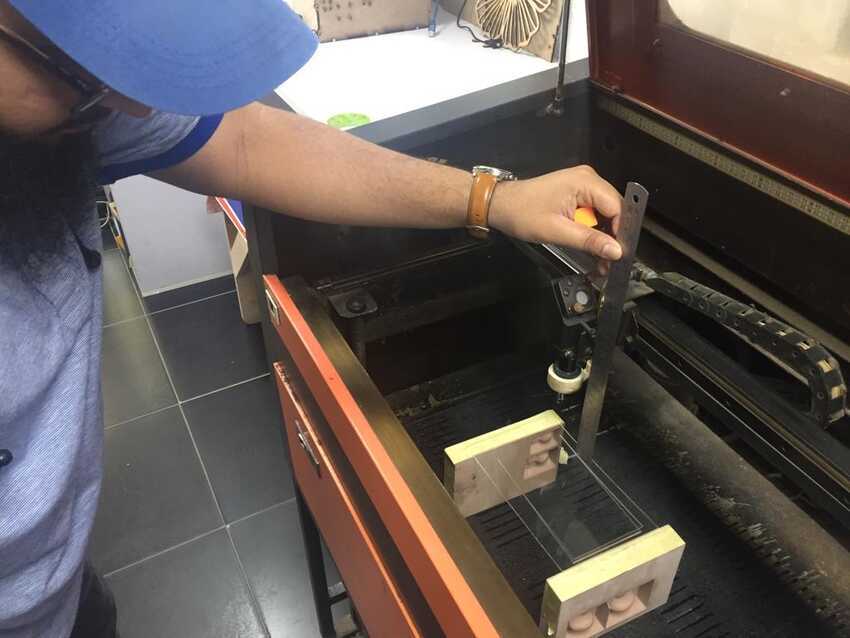
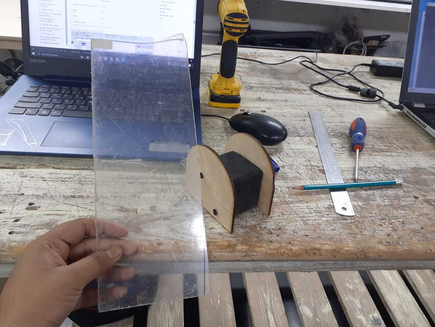
The setup for my assignment: I used FabLab Egypt’s Roland laser machine which has the ability to change the height by moving the bed in the Z axis. It allowed me to set up the acrylic piece far away from the nozzle. The rectangular piece of acrylic was taped on both ends to a chemical wood cut out each side so that the height will allow the bending to happen freely.
To start with, I started experimenting with the optimum settings for bending transparent acrylic 2.5/4.5mm. It was really exciting as u see the acrylic starts bending on its own. I started with 4.5cm height, 15 speed and 75 power. It was the same as the cut settings so after some counts it started to cut.
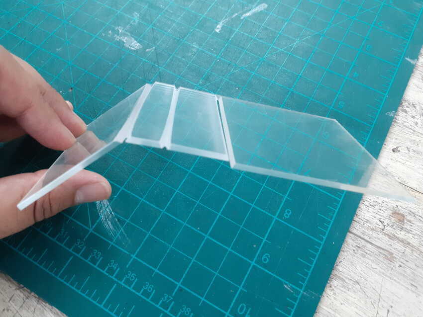
Then I lowered the power and maximized the speed example 200 speed and 40 power. But still it was too high. I also observed that as the nozzle comes to the edges of the line it starts to slow down so due to slow speed it cuts the edges of the bending part. Then I tried to increase the height so that it doesn't cut. I had made progress that it finally bent but still a cut was made throughout the line which was seen on the edges more.
Then I decided to increase the length of the line so that it doesn't slow down on the bending part. And increased the height also to 7 cm with the speed of 300 and power 40. It bended but still made a little cut. Due to time constraints I am satisfied with my progress and hope to return back for it after completing the documentation.
Comments from the instructors were very valuable that next time I should experiment with scan settings not cut settings for polishing for optimum settings for bending acrylic.

image image

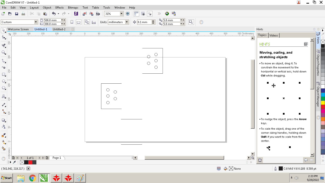
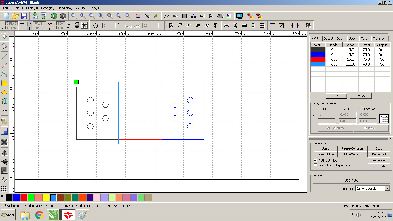
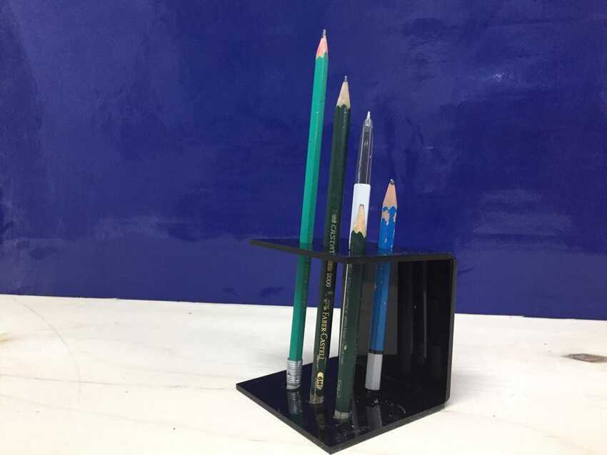
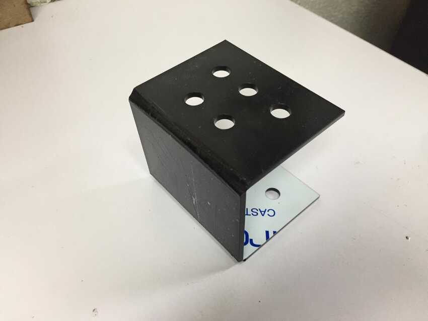
I wanted to make a pen/pencil holder as shown in this video. I sketched a simple design on Corel draw on the fablab’s computer directly, to send the cut command directly from it. According to my scrap size I drew a rectangle 22x8cm, imagining 7cm each side (3 sides) plus the 2 bending arcs so added 1 cm as a spare and gave room for bending freely. As for the pen pencil slots I drew a 9mm circle (diameter) and placed five of them indicating the olympics 5 interlocking rings :) Then I separated all 3 parts so that each section could be modified on the laser works (CAM software) with any definite settings. Then I remembered that the 2 parts on the edge should be the same, only the middle part will be cut after bending. I chose black acrylic scrap sheet and added its cut settings which are 15 speed and 80 power. I downloaded 3 files on the laser machine, so that after each process i could have time to prepare for the other like lowering the Z axis.

image
image image

DXF files Voila here is the result.

image image

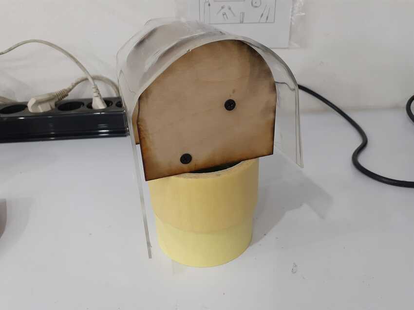
Since the laser machine bending process was not yet polished I tried another technique for bending the acrylic sheet but it was a manual process by providing hot air from the soldering station. The fablab specialist Omar abdulhameed whom I greatly appreciate for his guidance, had tried bending the acrylic before similar to what i was trying to do so he suggested the hot air temperature as well as the holding orientation of the tool itself. I had to first make a mold type shape for giving the acrylic sheet to have support on and take the shape of it. I cut 2 small pieces of circle on a rectangle and joined both by screws on a wooden cube which was left as a spare in the lab. 400 degrees celsius was suggested by my colleague Omar.
Observation for this process is that the acrylic didn't bend perfectly to give a circle shape. It needed another mold type which should be on top of the acrylic sheet as it is beneath it.
Voila here is the video.

image

I continued to go wild :)
Fablab Egypt had also screen painting equipment, as I couldn't manage to explore more machines which were outside the lab. I was inspired by Amany's work for this week so I thought why not let's give it a try. I really appreciate her guidance to better understand the process and successfully achieve it.
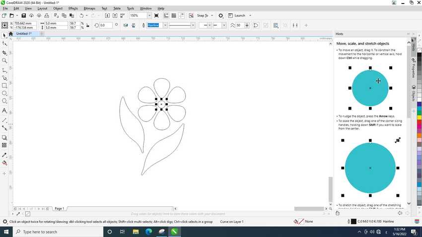
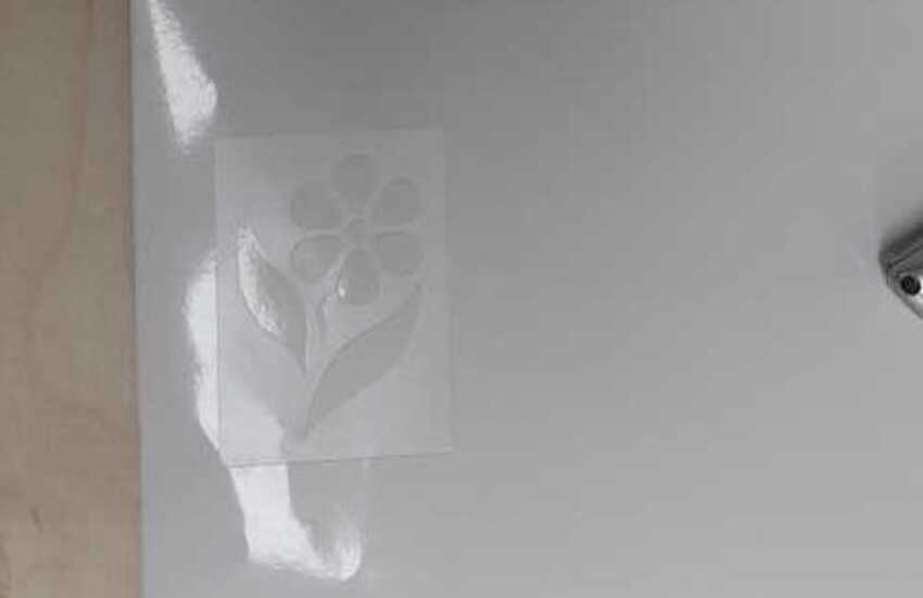
It all started with a simple design which we had to choose and cut in on a vinyl cutter. I chose a flower on my white cloth as I knew the die color was blue. I used the same vinyl sheet as Amany did. It was a white sheet.

image
image image

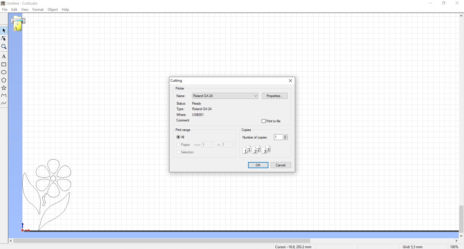
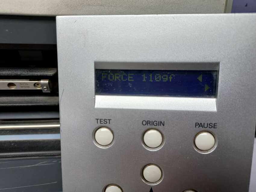
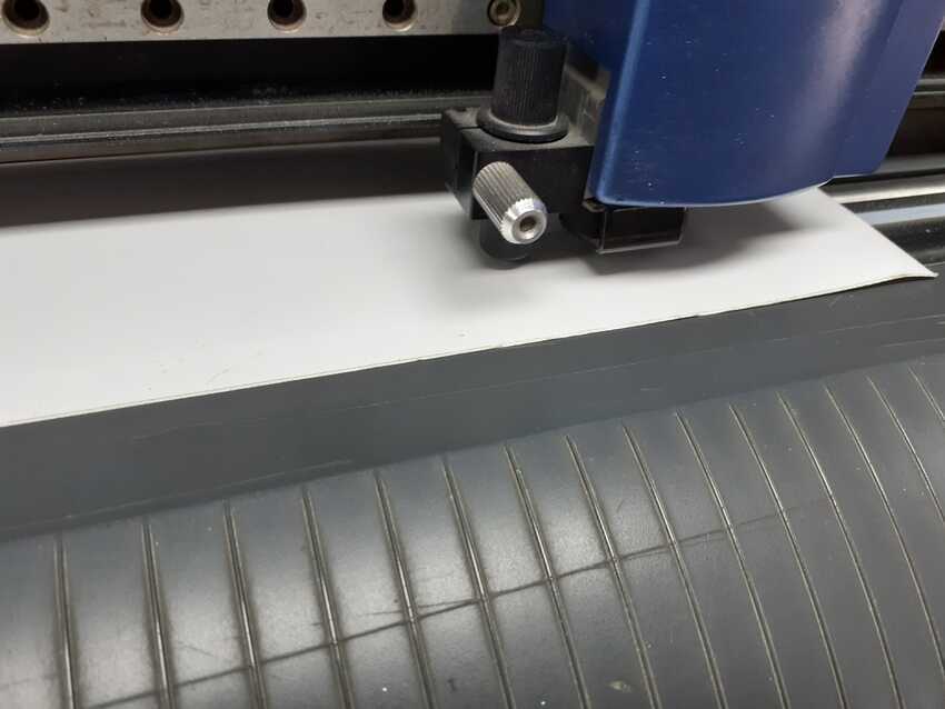
Process of vinyl cutting: I used the fablab’s vinyl cutter Roland machine and Cut studio as its CAM software. The process is simple, just added the white sheet and set the force to 120 on the machine. Then finally I did small setup to open my design on the Cut studio software (whole process is explained in my week 3's assignment ).
The files for this process is attached at the end of this section.

image image
image

The next process was to prepare the cloth and screen painting tools while taking every safety measure possible. I had to cut the pattern of the flower with a frame type rectangular shape outside the flower so that I could easily peel the stencil and use it for screen painting.
I carefully taped the cloth on a cardboard to keep it steady and positioned the wooden screen painting frame on it.
I poured some blue paint on it and started spreading it with the spreader of the screen painting tool, as shown in the video below . Then gently removed the wooden frame from the top of the cloth. Thankfully the first one turned out perfectly. I decided to do it on all 4 corners so I had calculated the process after that on how to use it theoretically. Cleaning of paint residue from beneath the frame was necessary as it doesn't spoil the white cloth. The cleaning process is very difficult with water and tissues as shown in the picture due to the residue. It didn't paint the second one perfectly. I went on with the 3rd and the fourth one.

image image
image

Observations:

    • Cleaning properly is a must till all the residue is clear.
    • I found out on the fourth one that due to speeding of liquid a small portion of sticker got loose in the paint and went beneath it which ruined the whole flower effect. So if using vinyl stickers for multiple screen painting, change the sticker on a new dry area.
    • As for the damage caused by the residue, I tried using a wooden spoon to fill out the gaps. The trick worked very nicely but still needs a hand of an artist for perfection and not to cause any more additional damage as I did by dropping the spoon on the cloth :)

Here is the final image. Flower files

image

Stay tuned for being more wild as I have taken an appointment with a water jet machine owner :)
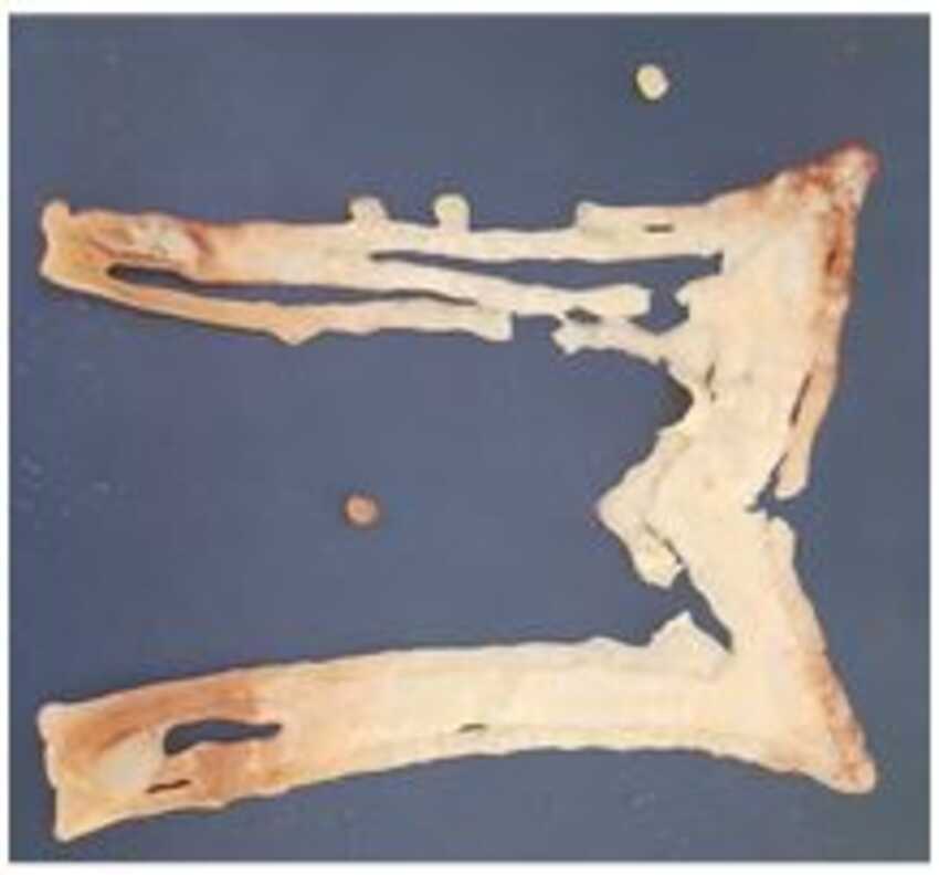
This may not be considered as this week's assignment as I didn't do it this week but as an intern in this lab I explored the pancake bot and made pancakes on it. It was an amazing experience to use a food machine. That is why I wanted to share here and add to this documentation for future memories.

image

Voila its done

To sum up, I completed the following:

    • √ Documented how you made your creation.
    • √ Described problems and how you fixed them.
    • √ Included your design files and ‘hero shot’ of the result.

#Challenges 1

The acrylic bending on laser cnc couldn't find the optimum settings as the laser beam seems to start cutting the material.

#Solution 1

Still needs further polishing of settings. Recommended to finish the final project first then work on all the due pending work.

Aknowledgment