#include // library for I2C connection
#include //liberary for LCD with I2C
LiquidCrystal_I2C lcd(0x27, 20, 4); // set the LCD address to 0x27 for a 16 chars and 2 line display
#define btngreen 9 // set button green on pin no. 9
#define btnred 8 // set button red on pin no. 8
#define ledgreen 2 // set led green for power on pin no. 2
#define ledred 3 // set led red for heater indication on pin no. 3
#define fan 0 // set fan for air direction on pin no. 0
#define sensor 10 // set thermistor sensor on pin no. 10
#define heater 1 // set heater on pin no. 1
float t; //create variable for temperature analog reading input
char bluetooth = '0'; //create variable for serial blutooth reading check
bool sys = false; // make the sys funcion off
void btngreen_int(void) //interupt command when pressed button green
{
sys = true; // make the sys funcion on
}
void btnred_int(void) //interupt command when pressed button green
{
sys = false; // make the sys funcion off
}
void setup() {
pinMode(btngreen, INPUT_PULLUP); // input pullup to gnd
pinMode(btnred, INPUT_PULLUP); // input pullup to gnd
pinMode(ledgreen, OUTPUT); // led green output
pinMode(ledred, OUTPUT); // led red output
pinMode(fan, OUTPUT); // fan via mosfet
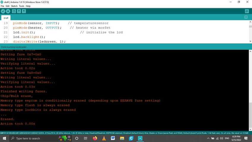
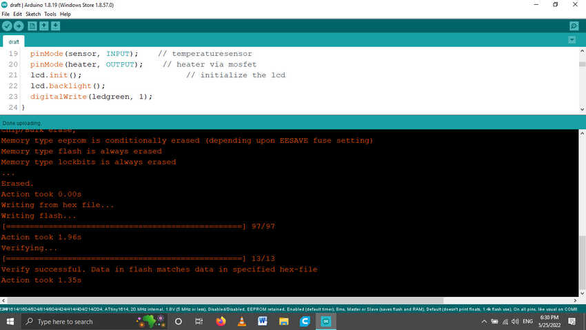
pinMode(sensor, INPUT); // temperaturesensor
pinMode(heater, OUTPUT); // heater via mosfet
lcd.init(); // initialize the lcd
lcd.backlight(); // blink black light
lcd.setCursor(1, 0); //set cursor to the first row on the first cell
lcd.print("Welcome"); // display welcome on LCD
delay(500); // delay 5 seconds for view it properly
attachInterrupt(digitalPinToInterrupt(btngreen), btngreen_int, FALLING); //interrupt command for button green which directs to button green funtion commands and its status is whenever it reads LOW.
attachInterrupt(digitalPinToInterrupt(btnred), btnred_int, FALLING); //interrupt command for red green which directs to red green funtion commands and its status is whenever it reads LOW.
digitalWrite(ledgreen, 1); // set green led on
digitalWrite(ledred, 0); // set red led off
Serial.begin(9600); // start serial communication for bluetooth
}
void loop()
{
if(Serial.available() > 0) { // if statement for serial availability
bluetooth = Serial.read(); // save the reading in this variable
if (bluetooth == '1')
sys = true; // when the reading decects 1 starts the sys function
else if (bluetooth == '0')
off(); // when the reading decects 0 starts the off function
}
if(sys) // when sys function called do the following
{
int temp = calcT(); // put the reading of calcT output in temp variable
if(temp <= 52 && temp >= 48) // when the temperature reaches between 48 to 52 do the following
limit(); // start limit reached function
if (temp < 48) // when the temperature is below 48 degrees do the following
hearteron(); // start heateron function
else if (temp > 52) // when the temperature is above 52 degrees do the following
off(); // start off function
}
else // when sys function is not called do the following
off(); // start off function
}
float calcT() { // wehn calcT function is called do the following
int t = analogRead(sensor); // read the thermistor sensor NTC and save it in this variable
float B = 3750; // do the calculations to return the temperature in degrees
float T0 = 298.15;
float R0 = 10000.0;
float R1 = 10000.0;
float rr1;
rr1 = R1 * t / (1024.0 - t);
t = 1 / (log(rr1 / R0) / B + (1 / T0));
return (float)(t - 273.15);
}
void hearteron()
{
lcd.clear();
lcd.setCursor(1, 0);
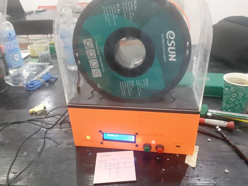
lcd.print("Heating T:");
lcd.setCursor(13, 0);
lcd.print(calcT());
digitalWrite(ledred, 1);
digitalWrite(fan, 1);
digitalWrite(heater, 1);
}
void limit() {
lcd.clear();
lcd.setCursor(1, 0);
lcd.print("Temperature:");
lcd.setCursor(13, 0);
lcd.print(calcT());
lcd.setCursor(2, 1);
lcd.print("Limit reached");
}
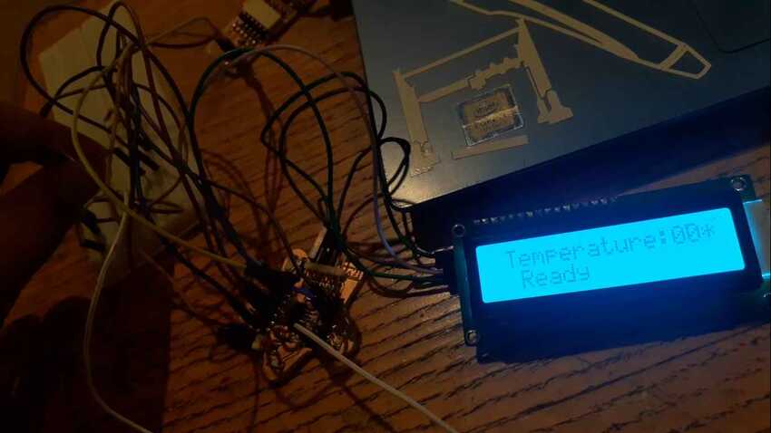
void off() {
lcd.clear();
lcd.setCursor(1, 0);
lcd.print("Off Temperature:");
lcd.setCursor(13, 0);
lcd.print(calcT());
lcd.setCursor(2, 1);
lcd.print("Ready");
delay(10);
digitalWrite(ledred, 0);
digitalWrite(heater, 0);
digitalWrite(fan, 0);
}


.jpg)
.jpg)