Week 3 Computer Controlled Cutting

Assignments:

Group assignment:

    • Characterize your lasercutter's focus, power, speed, rate, kerf, and joint clearance.
    • Document your work (individually or in group).

Individual assignments:

    • Design, lasercut, and document a parametric press-fit construction kit, which can be assembled in multiple ways. Account for the laser cutter kerf.
    • Cut something on the vinyl cutter.

Learning outcomes:

    • Demonstrate and describe parametric 2D modeling processes.
    • Identify and explain processes involved in using the laser cutter.
    • Develop, evaluate and construct the parametric construction kit.
    • Identify and explain processes involved in using the vinyl cutter.

Weekly practice Laptop stand parametric design

For my practice this week I had to design a laptop stand which is parametric regarding the thickness of the material and the kerf, by getting help from this video.
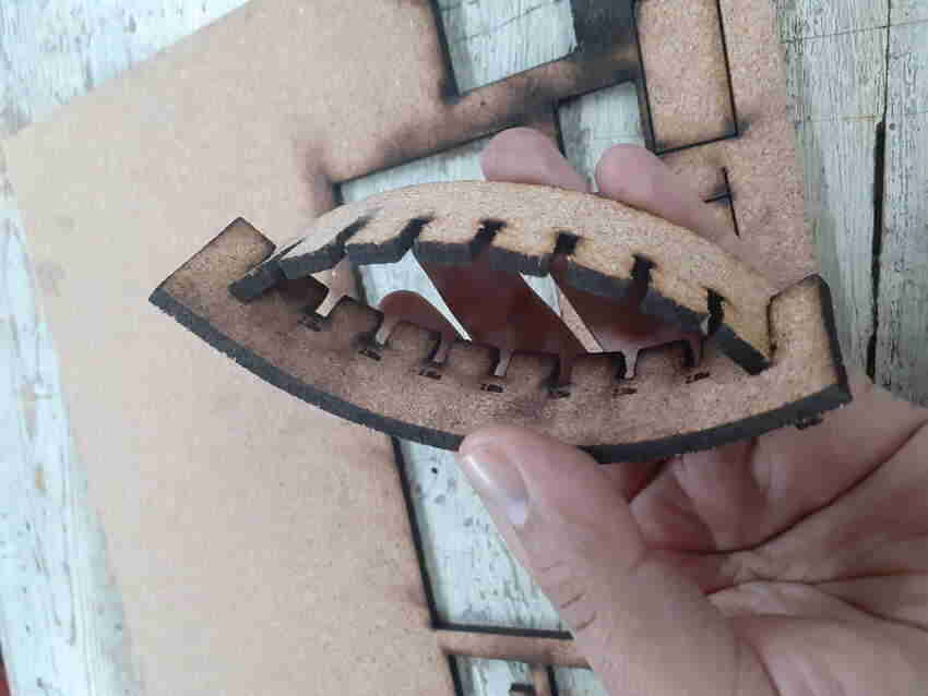
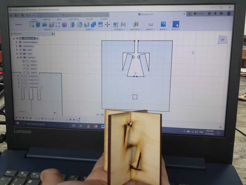
I wanted to push harder and explore more joints in my design so I started exploring different types of joints and fits.
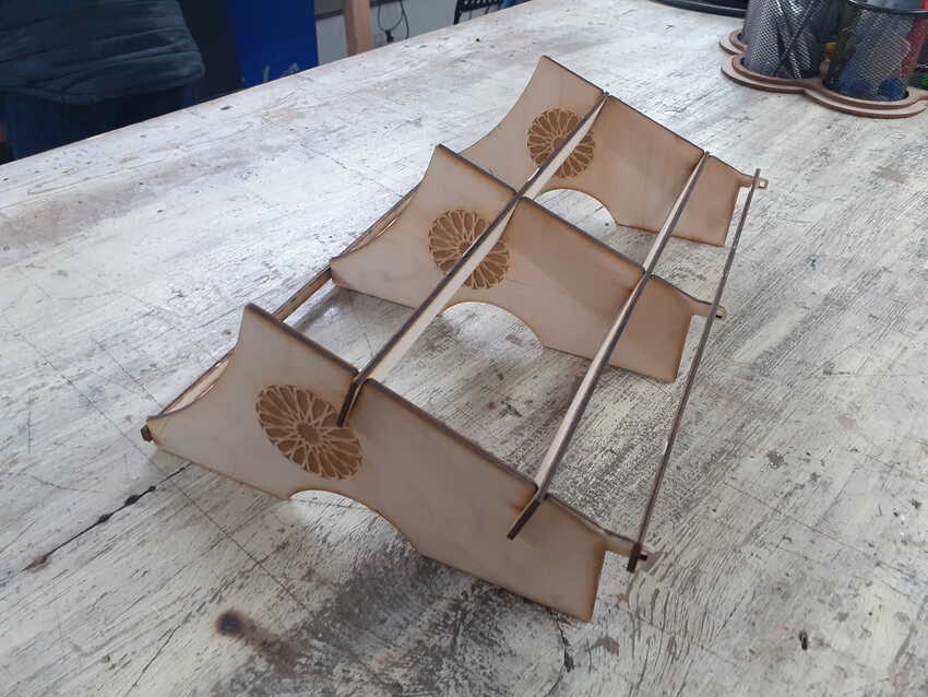
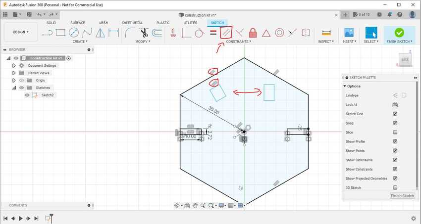
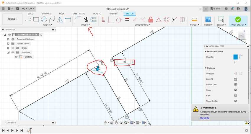
In the end I decided to apply finger, chamfered press fit, wedge and if possible snapping(flexure). Because some of them were new to me (like the flexure and the wedge) and some of them seemed important as they seemed commonly used like finger joints.
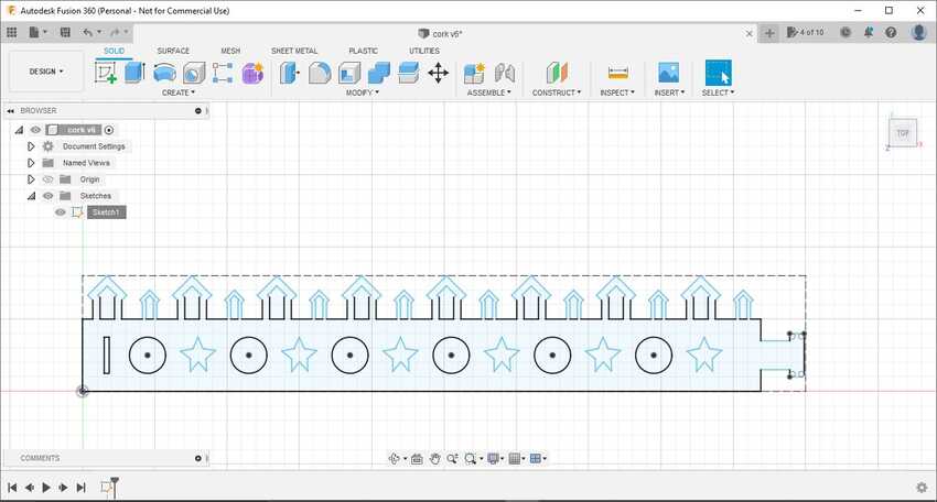
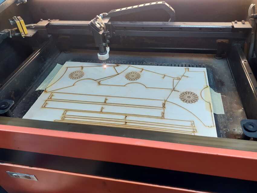
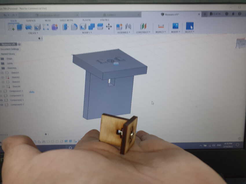
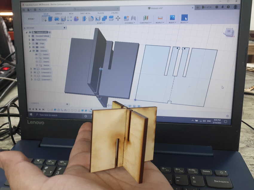
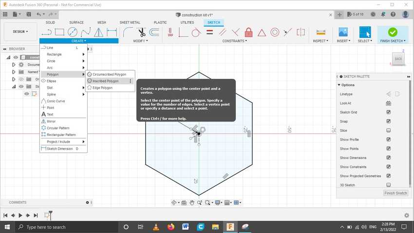
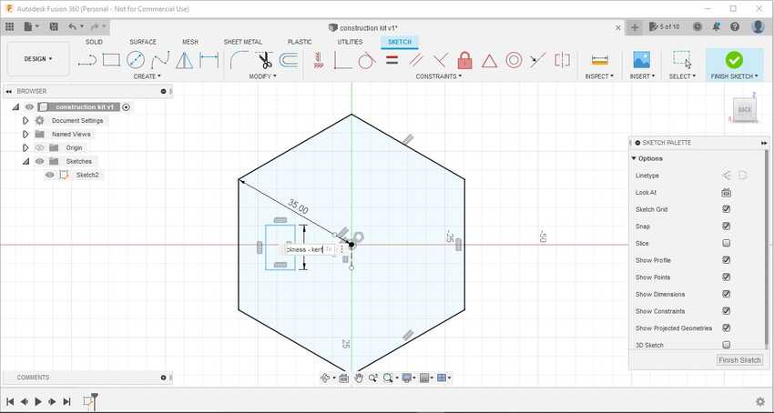
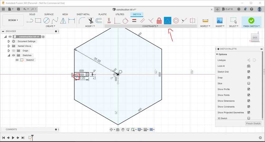
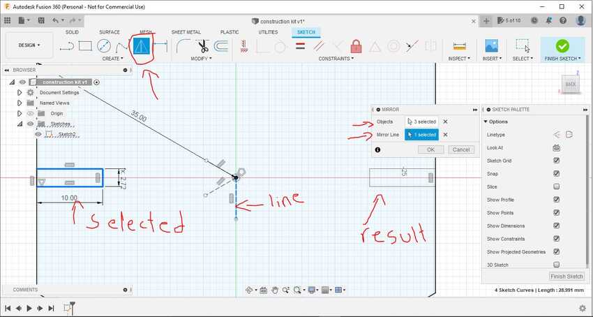
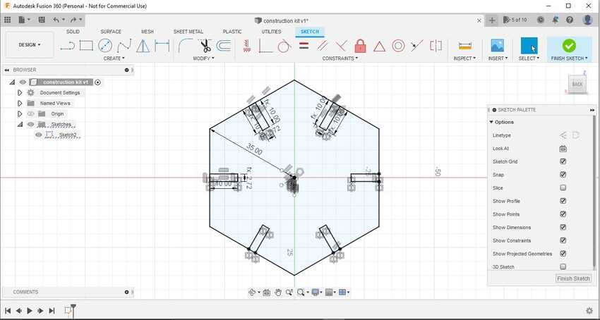
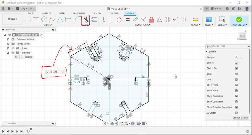
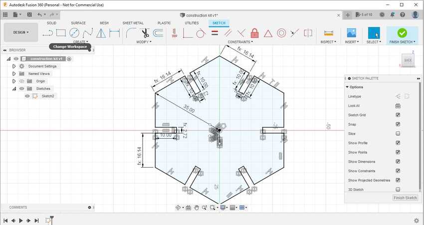
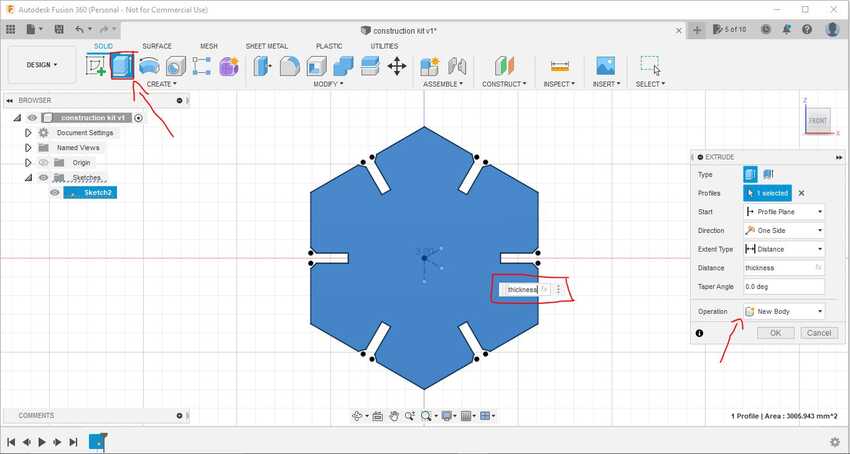
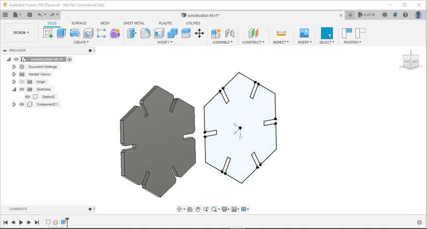
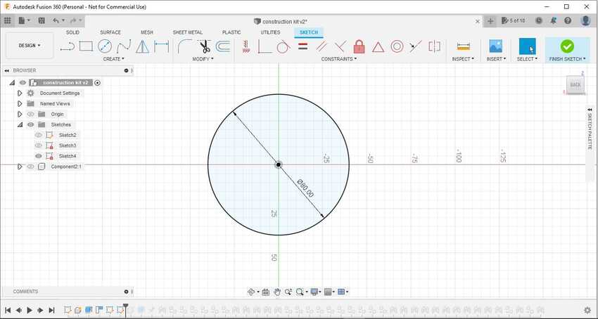
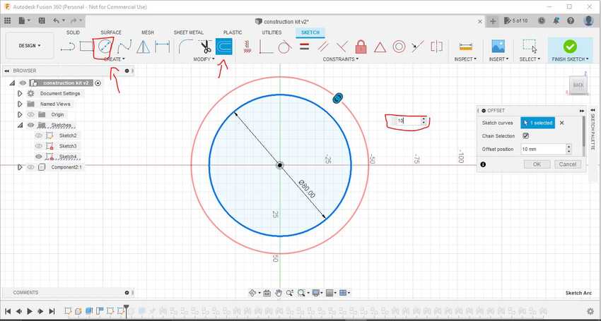
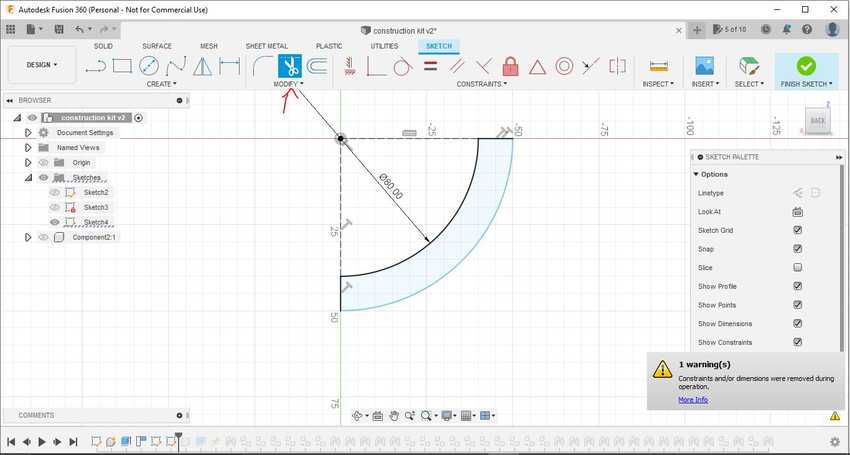
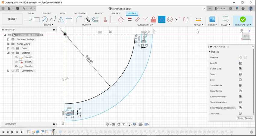
I then designed the model in 2d and 3d on fusion 360 and exported the dxf files for laser cut.
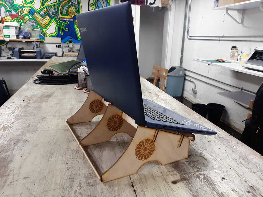
I successfully cut my laptop stand, but had some issues:

    • Measurements were a little bit small for the holder part, the laptop would slide down anytime.
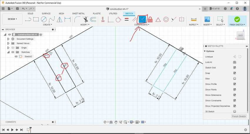
    • In my design I used a combine tool which left no trace of the sketch so I had to delete all the combine tools and make sketches for giving every side its parameter of kerf.
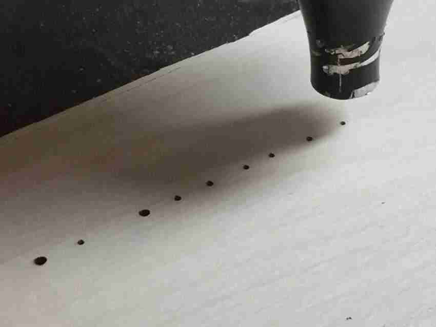
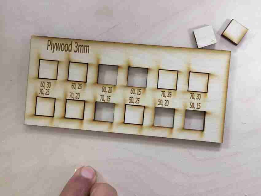
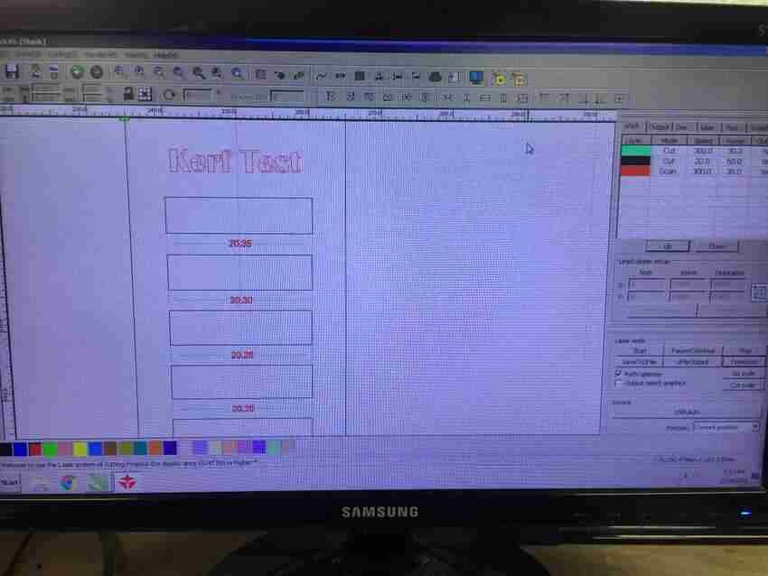
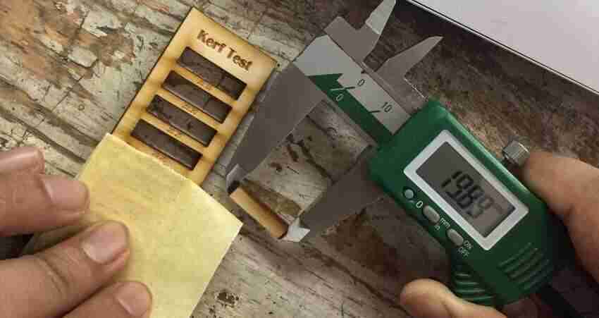
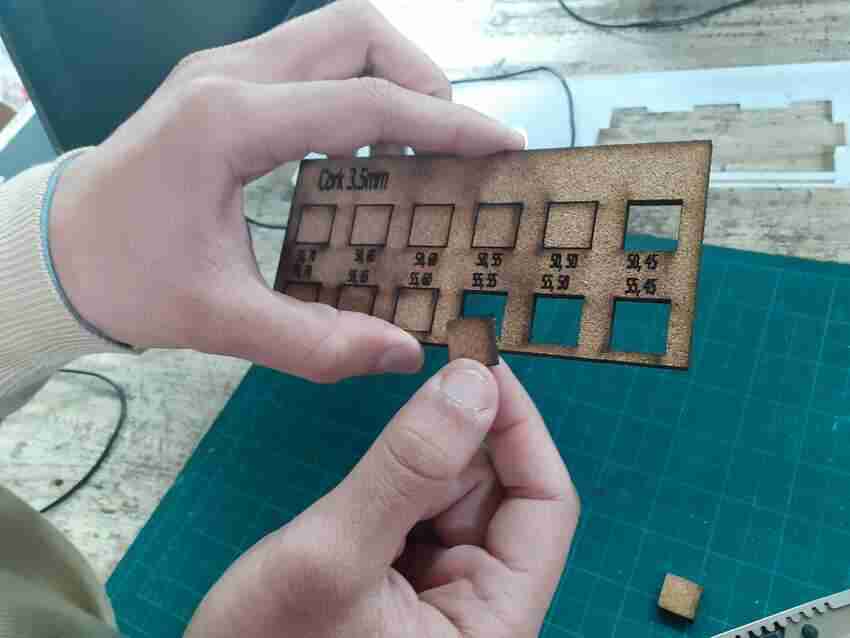
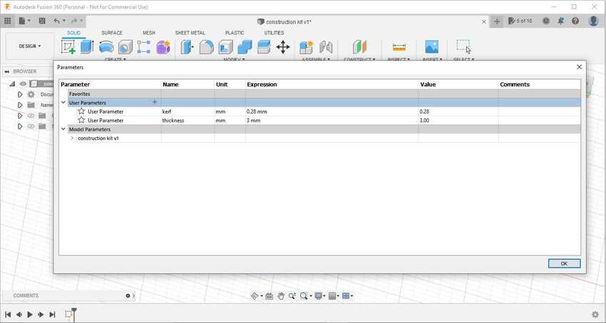
    • In our group assignment, we did a kerf test and agreed on the result that the kerf value is 0.28mm, after adding this value in my design still didn’t cut well. I think I may have not checked the focus well before cutting my laptop stand.

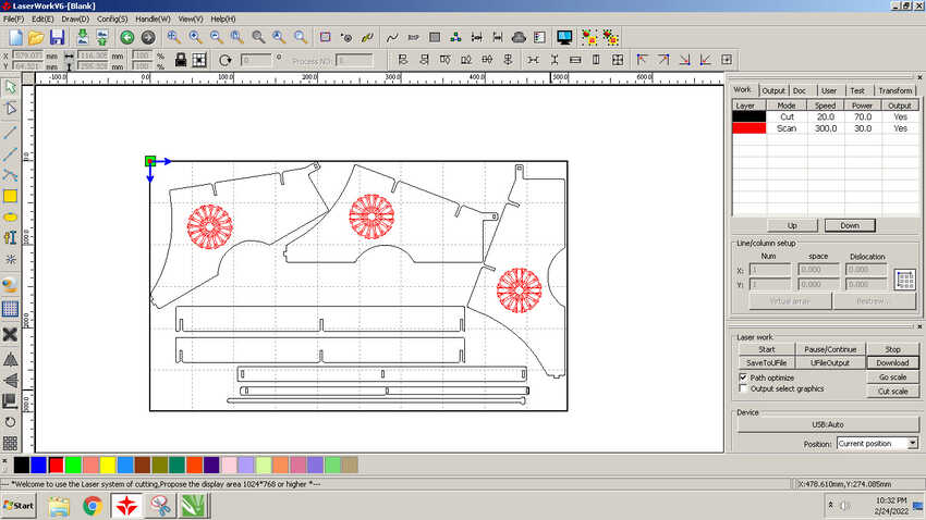
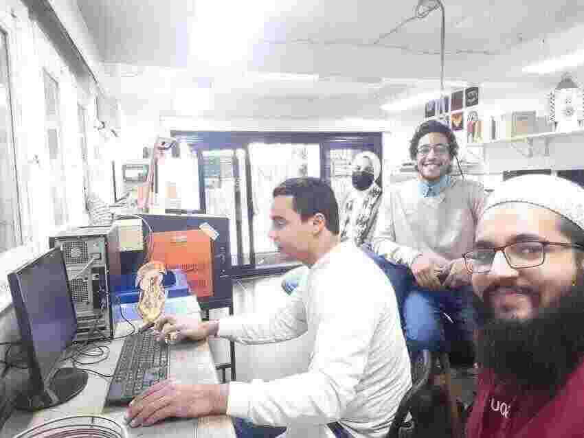
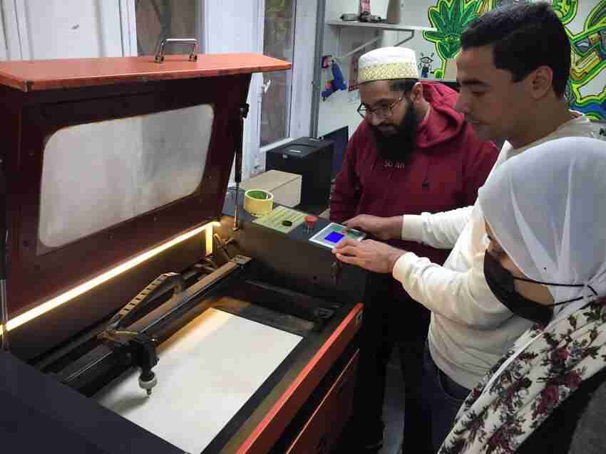
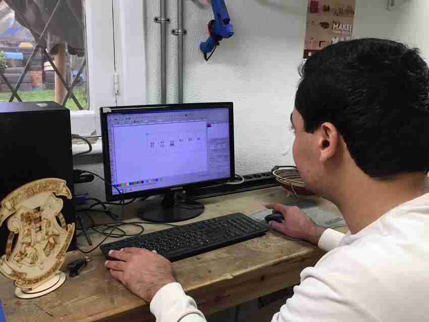
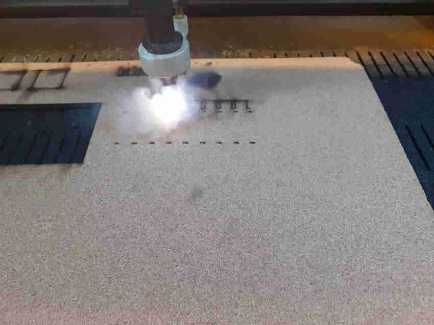
The best thing was to rearrange parts for cutting on the laser work application, it was like a puzzle to me and got found of it but due to time constraint I had to take help from the fablab specialist to speed up the process.
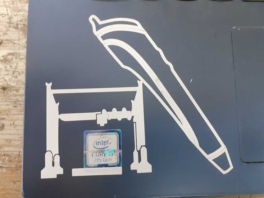
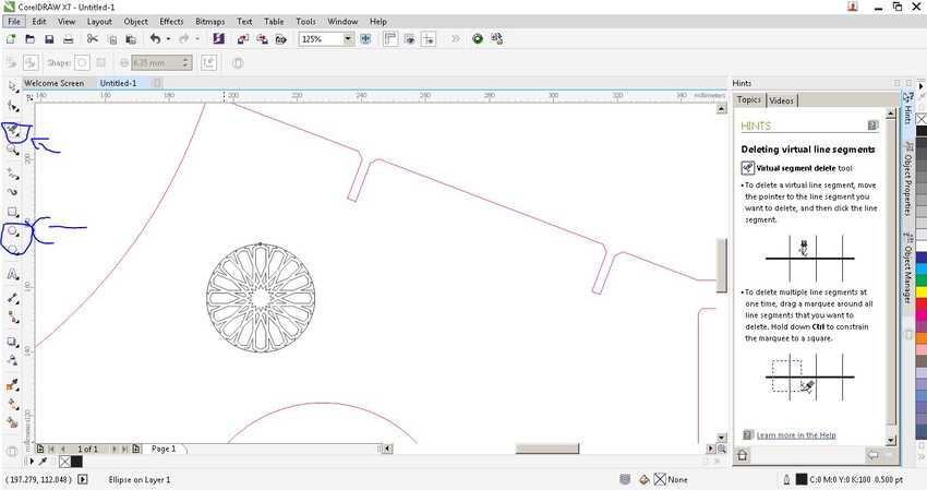
Also I wanted to fill the plain surface with a good design so I searched for it on the net and found this squared one but I eventually used coral draw to crop until I it looked for me a good design :)
Download laptop stand files (fusion360+.dxf)

image image
image image image

Here is the laptop stand.
I used wedge on the front, finger on the back and chamfered press fit on the top.

image image

Weekly assignments

Group assignments:

Here is the link to the group assignment page.
Eng Kamel, my instructor, conducted our group assignment in the beginning. He characterized fab lab egypt laser machine’s focus, power & speed and kerf on plywood 3mm, as it is the most common material used in the lab.

image
image

We started by measuring the focus of the machine. The focus is the smallest dot the laser makes, so we leveled the bed up and down until we reached the smallest dot then we measured the distance between the nozzle and the material which is around 8 mm.

image
image

Then moved on to the power & speed test by designing around 12 rectangles and giving each different speed and power settings on the laser work application. As far as I remember the result of the test was the clean cut settings power: 50 speed 15.

image
image

After getting the optimum focus and power and speed settings for the machine, we tested the kerf and clearance measurement. There are many kinds of designs to do that, but we started with the simple one to design many rectangles with 0.5mm difference in the length, so that the one which measures the 20mm length will be the kerf. Our rectangle length ranged from 20.35 to 20.00. Finally we found out that 20.25 measures exactly 20mm by digital caliper, so the kerf is 0.25-0.28

image

My role in the group assignment was to characterize focus, power & speed and kerf on a different material “cork” which I introduced for the first time of my life, that is why I was excited and eager to explore more about this material.
Pros and cons for the material cork:

Pros

.

1) Laser engraving cork results in excellent contrast so your design details pop. Line engraving for cork is recommended over area engraving due to powder (soot) build up, so you’ll want to design with that in mind.
2)Cork is a flexible material.
3)Cork is generally regarded as environmentally friendly. Cork production is considered sustainable because the tree is not cut down to obtain cork; only the bark is stripped to harvest the cork while the tree continues to live and grow.
For more info please click here.

Cons

.

1)When burns excreates foul small.
2)The black burn mark on the edge doesn’t look good.
3)Little bit fragile in sense of flexibility, as too much pressure applied will result in breaking the part.
4)Post processing for this material for me is still unknown.

1)Focus: after the group assignment the perspective of adjusting the focus has changed completely, as previously I only used the focus tool which the lab provided but now I can judge by the pulse dot thickness that the focus is correct or not.So this time I didn’t use the focus tool provided but instead I adjusted the bed till the laser makes the smallest dot. (From that moment I felt that this way is more accurate and assuring about the adjusting focus than using the tool, more efficient and easy also. I may continue this way in the future).
2)Power and Speed: I didn’t have enough knowledge about the material and what range to set for the test, so my instructor helped me by cutting manually from the control board random rectangles with various power, which resulted in as follow:
Power above 55 would burn the material and power lower than 50 doesn't cut the material properly. So the range was set power 50 and power 55 and for each I tested around 10 to 12 different speeds ranging from 45 to 70. It resulted in that power and speed both on 55 gives a very neat and clean cut, just have to apply little pressure to completely separate from the sheet.

image
image

3)Kerf test: I used for my kerf test the comb design following this site. I concluded that since this material has elastic properties so there will be no exact measurement of the kerf, all different sizes would fit one way or another. So the optimum solution is to prototype the joint only from the design and cut it separately and see if you are satisfied with the result or not. As I did for my construction kit I had cut the 2 parts once on the work and tested it by fitting them together also with the wood martial. Both were perfect fit, note: my design had the kerf for the plywood material 0.15mm. I tried also without kerf too it also was giving the same results.

image
image

Also I had to explore 2 new different joints so I had given the screw and snapping (flexure) joint. I designed them both on fusion 360. Before cutting on the laser machine I just wanted to be sure about the kerf measurement as my laptop stand didn’t work out the way I expected so I had cut the comb test again under the guidance of junior instructor Noha. and we found out that the kerf is 0.15. I modified this number on my parametric design with a simple edit in a cell which applied the changes to the whole design. And then only I had cut both joints.
I had designed 2 different type of snapping/flexure joint, first one was like a practice and a simple one (which by the way didn’t snap :)) and the other sample of a designed i loved as the top of the joint is seen as a slot but it is rigid by snapping in the middle. (this turned out to be a perfect snap)

image image

Weekly assignments Parametric Press-Fit Construction Kit

Individual assignments:

Parametric press fit construction kit, for this assignment I was inspired by this website . Because I loved the idea to make a ball shaped and if we changed the position of the top parts it can continue to make another ball shape linked together.
So I decided to design my kit in 2 parts, instead of squared shape hexagon shape and the other arc shaped.

image
image

I started with opening Fusion 360 application, then I saved the empty file to autosave all my work on the cloud. By doing this I can concentrate on my work without any worries of data loss. Then I opened the parameters feature to add 2 parameter for my design:

    • Kerf: 0.28 (after doing the kerf test in the group assignment).
    • Thickness: 3 mm, the thickness of the material.

In a new sketch, I started drawing the first part but instead of the square shape I thought the hexagon shape would be better to gain more surfaces for multiple assembly.
So I started by creating a centered polygon called inscribed polygon with an estimated measurement about 35mm.(but in the end I had to reduce it due to a proportionate aesthetic view till 25mm) I chose this feature because it can be measured as the diameter of the circle, so it made the visualizing part easier.

image
image

For making the press fit slot, I created a rectangle by using the rectangle tool. And added dimension for each side. So the base of the slot is thickness + kerf (parametric measurement). And the length of the slot is 10 mm. I used a small measurement so that all six sides when the other shape is fitted together it won’t intersect with each other.
Then I used the midpoint tool to snap that rectangle with the side of the polygon and make it a fully defined sketch.

image
image

I used the mirror tool to mirror the rectangle to the opposite polygon side, so I had to first draw a construction line in the middle for the mirror line, then I mirrored the rectangle by selecting the 3 sides of the rectangle. I love this feature because it saves time and effort while designing.
Next step was to add other rectangles on the other sides. As the sides of the polygons were not straight so I used the parallel constraint on the rectangle to parallel with the side needed to snap on. These types of constraints made my life easy, as instead of drawing a rectangle by line tool and giving it angle dimension and snapping it, I just used the rectangle tool and used the parallel constraint to have the same outcome.

image
image

Since the polygon has 6 sides, I only needed to draw 3 rectangles and then I thought of mirroring them to get the other 3 by only 1 command. So the remaining 2 rectangles as I snapped it (midpoint constraint) with the polygon side, to my surprise, were still under-defined but the first one became fully defined right away. So I had to add more constraints to make it fully defined. I used parallel constraint for the 2 sides of the rectangle and perpendicular constraint between the polygon side and any rectangle side. I had to do a troubleshooting type process by moving the rectangle to see which constraint to use.
After repeating this process on the third rectangle this is how it looks.

image
image

Then I used the trim tool to remove the top lines of the rectangle to make it as an opening for the slot, by this it automatically removed the midpoint constraints and became under-defined again. So I had to add a dimension constraint to replace it. But it needed little math in the process for making it accurately in the middle, even if the size of the polygon changes. I thought of an equation to subtract the length of the side polygon with the length of the base of the rectangle in the brackets, to divide the result with 2. There may be another simple way but this is the process which I thought of at that time.
I guess my love for math appears in my work :)
I repeated this process for the other 2 rectangles, and the charm of the mirror tool made the changes for the other 3 automatically. Now my sketch was fully defined.

image

In my sketch I added the chamfer on the edges of the slots, this will help to ease the process in the press joint, by using the chamfer tool from the modify drop down menu. At that time I didn’t know how much chamfer I should use, so I just went with 1.5mm and hoped it works.

image
image

In the end I closed the sketch by clicking on the finish sketch button, then I used the extrude tool and gave it a dimension named thickness which I saved in the parameters, because it resembles the thickness of the material.
Tip: In the extrude feature I used instead of a new body, a new component so that it will ease the process in the future while joining the parts.
Voila the first part is completed.

image
image

I added another sketch to start drawing the other part of the kit. From the inspiration image I didn't find its measurements, but I figured it only quarter part of a circle, that is why I started drawing a circle by using the circle tool and kept the origin as the center point of that circle to make it fully defined.
Then for the width of the part I made an offset of 10mm to that circle to the outside to make my part little bigger arc by increasing the radius.

image
image

Then I added lines to connect both circles together on the right side and bottom of the circles. And started to trim the unwanted circle parts, so that it would look like this.
For the press fit slot I used the same technique as I did on the previous part. By adding a rectangle. This time I wasn't confident to use the mirror in a more complex way, that's why I used the same rectangle tool for the second rectangle also. And added dimension and midpoint constraints on both of them.

image
image

Repeated the same steps of removing the top rectangle line and adding chamfered on the edges.
Also replacing the midpoint constraint with a dimension equation to make my sketch fully defined.
In this sketch I had to add another dimension constraint on the outer circle, radius 50mm so that finally it became fully defined.

image
image

Voila this is how it looks.
Then I extruded the second part and used the join assembly tool to view the 3d model.
I changed the appearance of the 2 parts to become more clearly visible by adding mahogany n pine wood color.

image
image

I then rendered the result for a better image appearance but didn't work due to the license issue.
Finally it is done.

image

I exported the files in .dxf format, and opened it on the laser work application which is CAM software for the laser machine here at Fablab Egypt. As shown in the 2 images I configured the power and the speed settings for each of the design according to the material used.
For the plywood 3mm speed 15 power 68-70.
Cork 3.5mm speed and power both 50. ( according to the test done)

image
image

As the cork material was something new for me, so I practiced cutting on it several times before the main assignment cutting to get the optimum result. (as seen in the pictures pulses dots for the focus, comb kerf test, power and speed test and a trial prototype both kit parts).
I also had to keep track of my usage so I always write it down somewhere, the time consumed is shown on the screen of the laser machine control board.

image

Here is a small video for the both parts.

image

Finally after cutting I assembled my kit in various ways.

image image image image image image

Vinyl cutting

My past experience with vinyl cutter machine is very low, I only got introduced to the machine in the internship as fablab specialist egypt, I had cut a 3d printer and a 3d pen and other varouis things.

image

For the assignment, I was thinking of a design to be needful this time like sign boards. I had my neighbor in my mind as there was a step in his house and everybody would just miss it.
So I Searched for a good sign image on the net something like “mind your step” sign in google images and something that looks good. While exploring I liked the concept of these three images:

    • 1) Overall circular shape for the sign and also the concept of multi color vinyl cutting.
    • 2)The character in this image has more features like hats and shoes which look great so I was thinking of replacing the character from image 1 with this one.
    • 3)I loved the concept of visualizing moving upwards or downward on the step so either I cut both of them or one of them according to my need.

The both side concept is one would be sticked / glued on the bottom of the step and other on the top, signifying to be cautious while going down or up.

image
image

Before practicals I wanted some knowledge on how the vinyl cutter machine works so I came across this great fablab Aalto video. Which explains well and in great details hands on experience with the fablab machine.
While watching this video I concluded these following:

    • Use a vector software for tracing any image from the net.
    • Use the Trace tool for tracing any image to get output of vector outline of that image.
    • Test the force and speed of the cutting machine.
    • Use transfer tape to transfer the cut part. And the techniques of pressing and peeling of stickers.

Due to time constraints I couldn't do 2 stickers but did only 1 of them. I started by opening inkscape on my laptop and imported the image which I liked the most, from the file menu.
The image was very big so that it didn't fit on my screen so I had to zoom out and scale it down a little bit to actually view it properly on my whole screen.
Next step I wanted to convert my image to vector outine so that the CAM software (cutstudio) would recognize the path. To do that I navigated to the Path menu and selected trace bitmap.
On the left side the tracing option appears, as I was not yet so intelligent I selected apply directly without changing any other settings. The result is generated in the preview box as well as behind the image. After confirming that both are present I closed the trace tool n started to work on the traced lines and deleted the image.

image
image

The whole image is traced and left as a group to I had to undo grouping by navigating to the object menu and selecting un-group.
After ungrouping, the vectors were still kind of linked together as I wanted to select only the character to change it, but all other things were also getting selected with it. So I used another tool called break a part which is found in the path menu. Now I had the freedom to delete move or even resize anything from the traced image design.
I changed the fill of the design to none, and the stroke to black hairline.

image
image

This is how it looks after all these steps.
After finishing the first picture, I started with the second one to get the nice looking character into my design. I repeated all steps again from the point of importing a new image till completing and moving the character in the right position.
Then I exported the image after grouping it to .dxf format to make it easy for the next application to read the file.

image
image

From this process onwards, I continued my work on the desktop provided in the fab lab Egypt for the vinyl machines (connected to the machine at all times). I copied the .dxf file named sign3 to the USB and then opened it in the illustrator application, by opening the application and importing the .dxf file. All this hustle is because the cutstudio application does not support/open .DXF files! (CAM vinyl ), that is why I used Illustrator to import the .DXF file and then exported it to .ai Japanese version (which is the only format accepted in cutstudio). So then I “saved as” the opened file with the name of sign3 japan :) and chose the japanese version and clicked ok.

image
image

I opened the cutstudio application and imported my file in the application. I double checked the size of my design just to make sure that in all these processes the properties have changed or not.
Thanks to fab lab specialist Omar Hamid showed me how to check the size of the design, by selecting it all and going to its properties in the right click menu. It was a very minute difference like 0.04 or something which was acceptable for me. I felt so relieved that all is ok till now the result of the struggle is not wasted :)
At last the practical machining part came, I finally turned the machine on, opened the lever to put the vinyl sheet and placed the yellow vinyl sheet from the back of the machine so that as you push it, it comes out to the front of the machine from the middle sheet slot.

image
image

The vinyl sheet was a small piece of sheet so that is why instead of the roll option on the machine , I selected a piece by clicking the down button arrow and then the enter button. This way the machine will automatically move the sheet back and forth till the both ends, to detect the length of the piece of sheet inserted. It will display the length in the end.
Once all sorted out, I came back to the desktop and navigated to the cutting option from the file menu, into properties and synced the application with the machine. I clicked on the get from machine button to start the sync. Once the length and the width of the vinyl sheet is updated, that is the indication of sync, I clicked on ok.

image
image

I clicked on the ok button again on the cutting option prompt.
As I pressed the ok button, I prayed to have a clean and good cut from the beginning as I didn't want to waste a piece of vinyl sheet :)
My design integrated 2 colors yellow and black so I had cut the same design on both of them. The reason for the cut on the yellow vinyl piece is to get the exact location of each detail as I stick the black color parts on it.

image image

I assembled the black pieces in the same location on the yellow piece, and after reaching my neighbors house I applied the transfer tape and started pressing on it for good adhesion. Thanks to the video mentioned above, all the techniques were very clear and helpful in practicals.
I peeled the whole sticker with the transfer tape and stuck it on the wall which had the best view of people coming towards it. Pressed again on it so that the vinyl sheet sticks on the wall. Then gently I peeled off the transfer tape.

image image
image image

Voila
Resource management: My neighbor was so happy with the idea and loved the vinyl design stickers that he told me to stick the remaining from the black sheet on the opposite side of the sign :)

image

Hooray its done.

To sum up, I completed the following:

    • √ linked to the group assignment page.
    • √ Explained how you parametrically designed your files.
    • √ Documented how you made your press-fit kit.
    • √ Documented how you made your vinyl cutting.
    • √ Included your original design files.
    • √ Included your hero shots.

Files: Download construction kit files (fusion360+.dxf) Download vinyl related files (inkscape+.dxf+.ai)

#Challenges 1

Nothing seem to work out in the first time, like in the weekly practice when I cut the laptop stand it didn’t turn out the way I imagined.

#Solution 1

As it is wisely said try try untill you succeed, have faith and learn from your mistakes. As I learned to cut a small prototype first then only start cutting something big. It avoid wastage and more accurate results.

#Challenges 2

Double check every tiny details, I had designed a crown to cut on the cork material but sadly i didn't check the material lenght before designing, due to time constraint i couldn’t manage to change the whole design again.

#Solution 2

Adapt in any situation is the true skill learned in this academy, to be under pressure but to make things done. As I was feeling guilty for wasting my time for nothing, Fablab specialist/junior instructor Noha supoorted my by giving me hope to cut one of my part from the construction kit on that material, that way achieved everything in 1.

image

Aknowledgment

    • √ Special Thanks to Fablab specialists Omar and Noha for their productive ideas and supoort while I was working on the machines.
    • √ Thanks a lot to Krisjanis Rijnieks who made useful videos for weeks' assignments at Aalto Fablab.