9. Embedded programming
This is embedded Programming Week.
Research
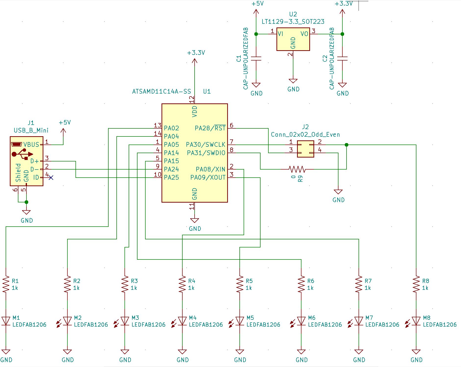
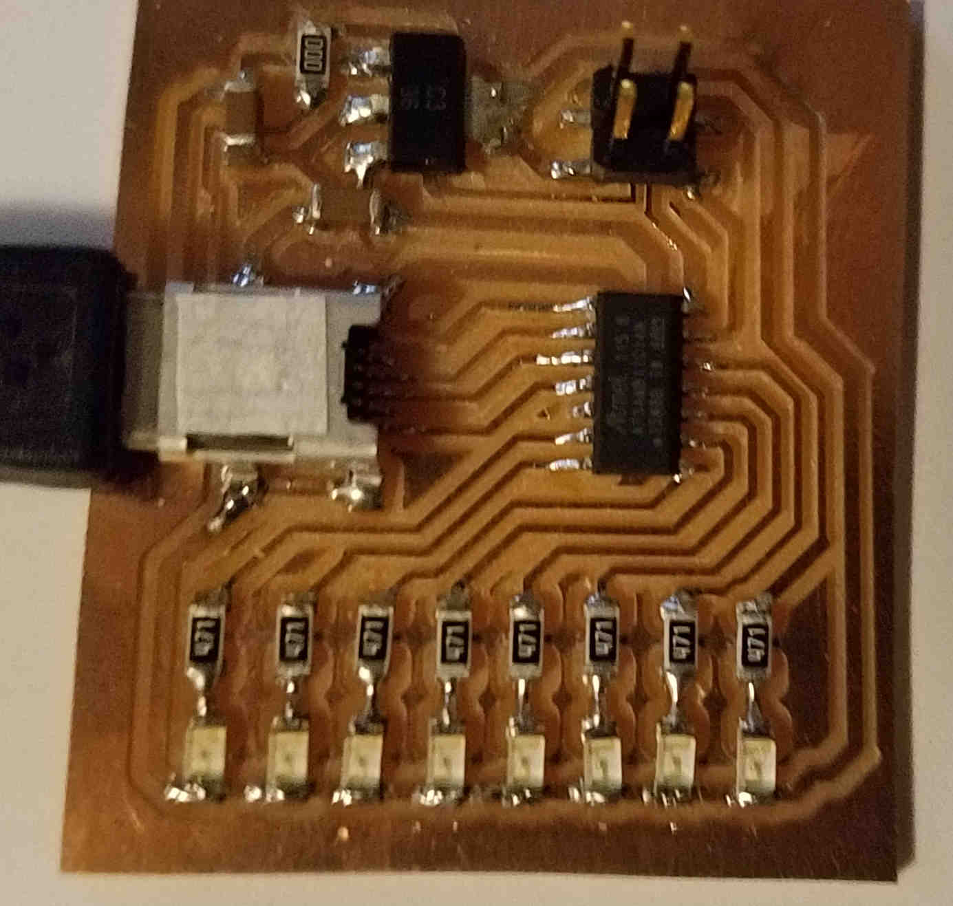
Created a new board schematic that has 8 LEDs on it driven by the SAMD11C14 microcontroller.
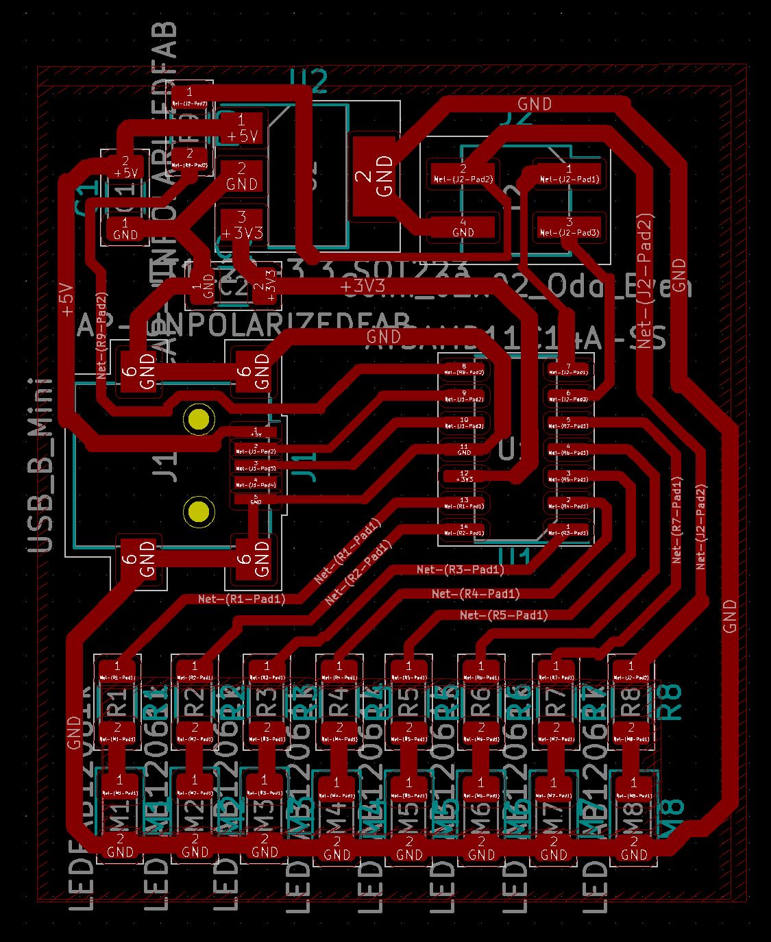
Then the PCB was wired for the 8 LEDs:
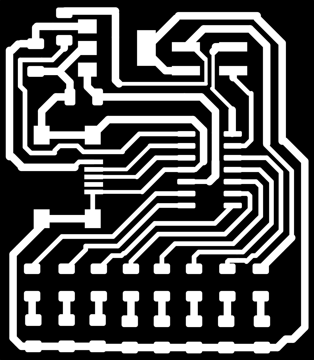
A PNG file was then exported in Black and White, with the copper circuit appearing in white.
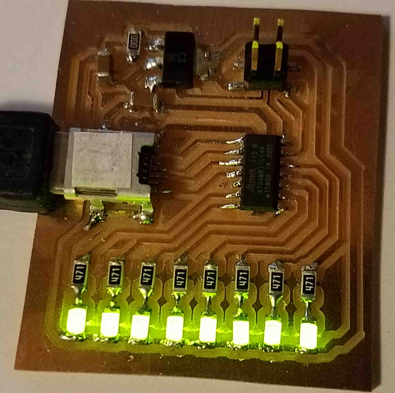
It was then Milled and soldered up:
First Programming the Programmer:
PS C:\Users\Dennis Leak> cd “C:\Users\Dennis Leak\Documents\FabAcademy\PCB_Circuits\edbg-master”
PS C:\Users\Dennis Leak\Documents\FabAcademy\PCB_Circuits\edbg-master> .\edbg-windows-r29.exe -bpv -e -t samd11 -f free_dap_d11c_mini.bin
Debugger: ATMEL Atmel-ICE CMSIS-DAP J42700050854 01.00.0021 (SJ)
Clock frequency: 16.0 MHz
Target: SAM D11C14A (Rev B)
Erasing… done.
Programming.... done.
Verification.... done.
PS C:\Users\Dennis Leak\Documents\FabAcademy\PCB_Circuits\edbg-master>
Second Programming the DUT (our 8 LED card) with the Atmel Bootloader:
PS C:\Users\Dennis Leak\Documents\FabAcademy\PCB_Circuits\edbg-master> .\edbg-windows-r29.exe -bpv -e -t samd11 -f sam_ba_Generic_D11C14A_SAMD11C14A.bin
Debugger: Alex Taradov Generic CMSIS-DAP Adapter B9039685 v0.1 (S)
Clock frequency: 16.0 MHz
Error: invalid response during transfer (count = 0/1, status = 0)
Didn’t program because DUT did not have power. Supplied Power:
PS C:\Users\Dennis Leak\Documents\FabAcademy\PCB_Circuits\edbg-master> .\edbg-windows-r29.exe -bpv -e -t samd11 -f sam_ba_Generic_D11C14A_SAMD11C14A.bin
Debugger: Alex Taradov Generic CMSIS-DAP Adapter B9039685 v0.1 (S)
Clock frequency: 16.0 MHz
Target: SAM D11C14A (Rev B)
Erasing… done.
Programming.... done.
Verification.... done.
PS C:\Users\Dennis Leak\Documents\FabAcademy\PCB_Circuits\edbg-master>
Set up the programmer to Program the FabLab LED board with the Arduino Firmware:
Windows PowerShell
Copyright (C) Microsoft Corporation. All rights reserved.
Try the new cross-platform PowerShell https://aka.ms/pscore6
PS C:\Users\Dennis Leak> cd “C:\Users\Dennis Leak\Documents\FabAcademy\PCB_Circuits\edbg-master”
PS C:\Users\Dennis Leak\Documents\FabAcademy\PCB_Circuits\edbg-master> dir
Directory: C:\Users\Dennis Leak\Documents\FabAcademy\PCB_Circuits\edbg-master
Mode LastWriteTime Length Name
---- ------------- ------ ----
d----- 2/22/2022 1:21 PM edbg-master
-a---- 2/18/2022 9:33 AM 539396 edbg-windows-r29.exe
-a---- 2/23/2022 3:10 PM 6536 free_dap_d11c_mini.bin
-a---- 3/1/2022 11:31 PM 13067 ProgrammingLog.docx
-a---- 2/18/2022 9:24 AM 3904 sam_ba_Generic_D11C14A_SAMD11C14A.bin
PS C:\Users\Dennis Leak\Documents\FabAcademy\PCB_Circuits\edbg-master> .\edbg-windows-r29.exe -bpv -e -t samd11 -f sam_ba_Generic_D11C14A_SAMD11C14A.bin
Debugger: Alex Taradov Generic CMSIS-DAP Adapter B9039685 v0.1 (S)
Clock frequency: 16.0 MHz
Target: SAM D11C14A (Rev B)
Erasing… done.
Programming.... done.
Verification.... done.
PS C:\Users\Dennis Leak\Documents\FabAcademy\PCB_Circuits\edbg-master>
Now update the Arduino IDE to support compiling the code for the SAMD11C14 microcontroller:
This firmware only allows arduino to program the chip via USB. Let’s now install the correct board info to arduino so we can do that.
In the arduino software, go to File→Preferences and click the icon next to “Additional Boards” and paste the following:
https://www.mattairtech.com/software/arduino/package_MattairTech_index.json
Then you need to install the SAMD boards. In Arduino go to Tools→Boards→Board manager
Search for “SAMD” and install the “MattairTech” one only.
Once this is installed (it will take a bit of time) We can write some arduino code to run on our new board. Let’s start with a blinky program. Looking at the pinout of the SAMD11C, we can choose a pin to connect an LED to on a breadboard.
After writing the following Arduino sketch:
int led = 2;
// the setup routine runs once when you press reset:
void setup() {
// initialize the digital pin as an output.
pinMode(led, OUTPUT);
}
void loop() {
digitalWrite(led, HIGH); // turn the LED on (HIGH is the voltage level)
delay(1000); // wait for a second
digitalWrite(led, LOW); // turn the LED off by making the voltage LOW
delay(1000); // wait for a second
}
The code was compiled and downloaded:
Sketch uses 9416 bytes (76%) of program storage space. Maximum is 12288 bytes.
Atmel SMART device 0x10030006 found
Device : ATSAMD11C14A
Chip ID : 10030006
Version : v2.0 Nov 22 2017 12:56:25
Address : 4096
Pages : 192
Page Size : 64 bytes
Total Size : 12KB
Planes : 1
Lock Regions : 16
Locked : none
Security : false
Boot Flash : true
BOD : true
BOR : true
Erase flash
done in 2.243 seconds
Write 9768 bytes to flash (153 pages)
[==============================] 100% (153/153 pages)
done in 23.893 seconds
Verify 9768 bytes of flash
[==============================] 100% (153/153 pages)
Verify successful
done in 0.060 seconds
CPU reset.
It Worked! The LED on Pin 2 is blinking!
Next I modified the program to blink the 8 LEDs in a pattern:
int led0 = 31;
int led1 = 15;
int led2 = 14;
int led3 = 9;
int led4 = 8;
int led5 = 5;
int led6 = 4;
int led7 = 2;
int i = 0;
byte array[] = { 1, 2, 4, 8, 0x10, 0x20, 0x40, 0x80,
0x40, 0x20, 0x10, 8, 4, 2, 1, 0x00,
0x81, 0xC3, 0xE7, 0xFF, 0xE7, 0xC3, 0x81,0x00
};
// the setup routine runs once when you press reset:
void setup() {
// initialize the digital pin as an output.
pinMode(led0, OUTPUT);
pinMode(led1, OUTPUT);
pinMode(led2, OUTPUT);
pinMode(led3, OUTPUT);
pinMode(led4, OUTPUT);
pinMode(led5, OUTPUT);
pinMode(led6, OUTPUT);
pinMode(led7, OUTPUT);
}
void loop() {
OutputLedByte( array[i] );
i++;
if( i > 23)
{
i = 0;
}
delay(250); // wait for a while
}
void OutputLedByte( byte leds ) {
if((leds & 0x01) == 0x01) digitalWrite(led0, HIGH); else digitalWrite(led0, LOW);
if((leds & 0x02) == 0x02) digitalWrite(led1, HIGH); else digitalWrite(led1, LOW);
if((leds & 0x04) == 0x04) digitalWrite(led2, HIGH); else digitalWrite(led2, LOW);
if((leds & 0x08) == 0x08) digitalWrite(led3, HIGH); else digitalWrite(led3, LOW);
if((leds & 0x10) == 0x10) digitalWrite(led4, HIGH); else digitalWrite(led4, LOW);
if((leds & 0x20) == 0x20) digitalWrite(led5, HIGH); else digitalWrite(led5, LOW);
if((leds & 0x40) == 0x40) digitalWrite(led6, HIGH); else digitalWrite(led6, LOW);
if((leds & 0x80) == 0x80) digitalWrite(led7, HIGH); else digitalWrite(led7, LOW);
}
Here is a video of the LED board:
The video was too large to upload, so here is a picture of the LEDs lit up.