Week 2: Project Management
Final Project
For this week I worked on defining my final project idea and started to getting used to the documentation process.
- Decided to produce a final project called: Kiddi-Coder The Kiddi-Coder is a hardware coding puzzle display, that introduces programming concepts to middle school students.
The pieces of the Kiddi-Coder will include:
- Start/Clock = A start block which has a pushbutton to start the processing. Included is a clock with a knob to control the speed of execution
- Set A, B = Initializes variables A and B to a user setting
- Show A, B = An LCD display shows the current values of A and B
- Math = A puzzle piece that can perform add, subtract, multiply and divide
- Compare = Compares A and B with comparisons >, <, <=, >=, and =. Directs the flow of the program.
- GoTo = Jumps to another location in the program
- Input A, B = Allows setting of the variables A and B
- Output = Allows the program to send information to a device, like DC motors, Stepper Motors, LEDs, and maybe an M&M dispensing device.
- End = The end of the program.
General Information
- The coding puzzle pieces will be magnetically attached to two vertical rods (one is +5 volts, the other ground) which powers each block.
- The base will hold the power supply.
- Each puzzle piece will be composed of a base part containing the microcontroller, and will be the same for all coding pieces.
- The top cover of the puzzle piece will have a daughter board that plugges into the base unit and wires up the specific function.
- Each puzzle piece will have a Photo transistor pointing up, that receives previous puzzle serial commands and an infared LED pointing down, to send commands to the next coding puzzle piece.

Research
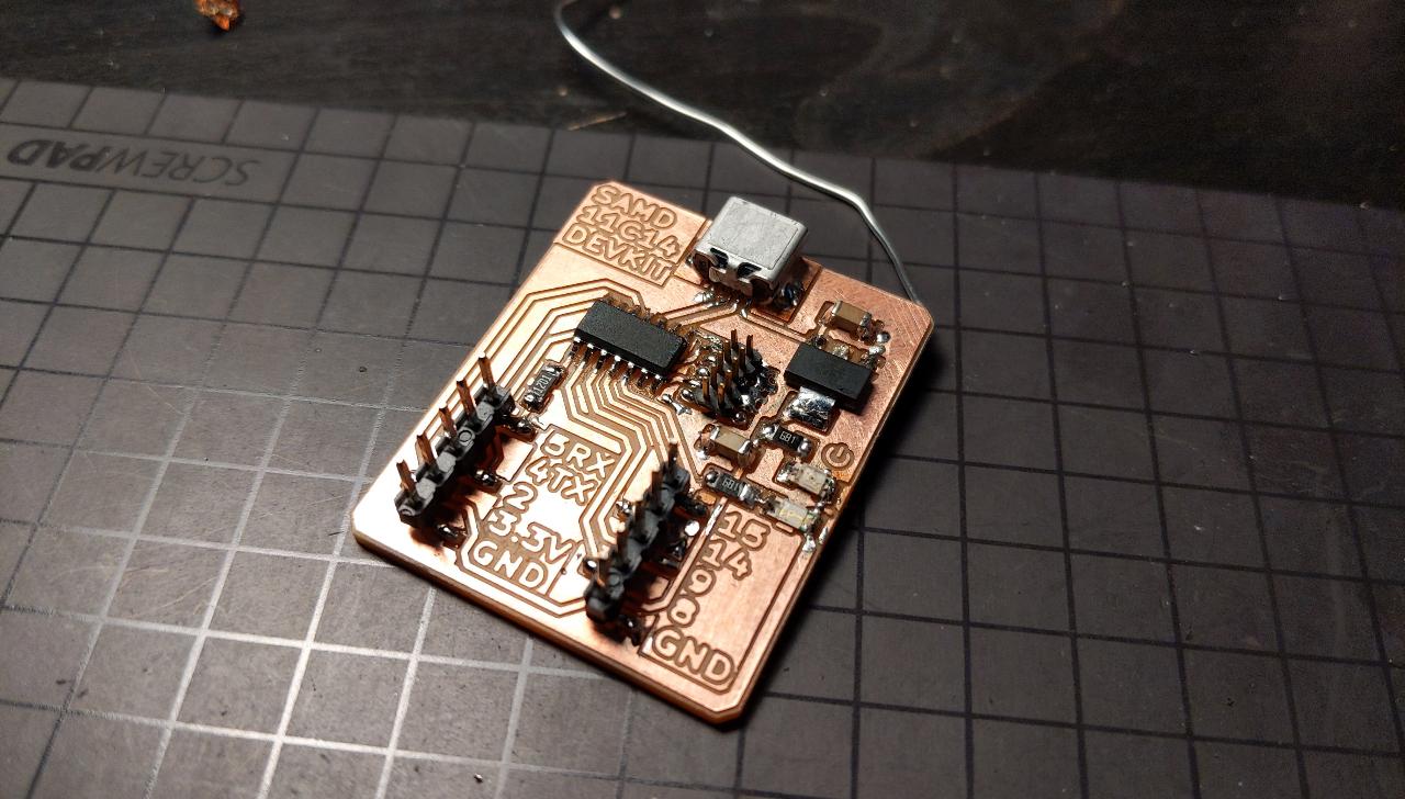
I got the idea for the base puzzle processor board from Quentin Bolsee (previous FabAcademy student):
https://fabacademy.org/2020/labs/ulb/students/quentin-bolsee/projects/samd11c_devkit/
The required technologies that will be used in the project include:
- Microprocessor design and coding.
- Schematic creation and PCB layout and routing.
- Milling the Printed Circuit Boards.
- CAD layout of the Mechanical components.
- Milling of the frame using the Shop Bot.
- Creating the 3D plastic frames of the coding puzzle pieces.
- Using the 3D printers form the many code puzzle Base and Tops.
- Use the Vinal cutter for graphics and wording.
2D and 3D Modeling
Modeling and design goes here.
Materials
- Plywood 1/2 inch, furnature grade, 4 foot by 4 foot.
- 6 chromed steel rods 3/8 inch in diameter, 24 inches long.
- PLA or ABS plastic for the 3D printer.
- Screws, nuts and bolts.
- BUD box to hold the Power Supply.
- Power Supply for the +5 Volts at 1 amp.
Last update:
February 23, 2022