Week 3: Vinyl Cutter and CAD with Parametric Parameters
For the individual Assignment:
individual assignment:
Cut something on the vinylcutter
Design, lasercut, and document a parametric construction kit, Accounting for the lasercutter kerf, which can be assembled in multiple ways, and for extra credit include elements that aren’t flat
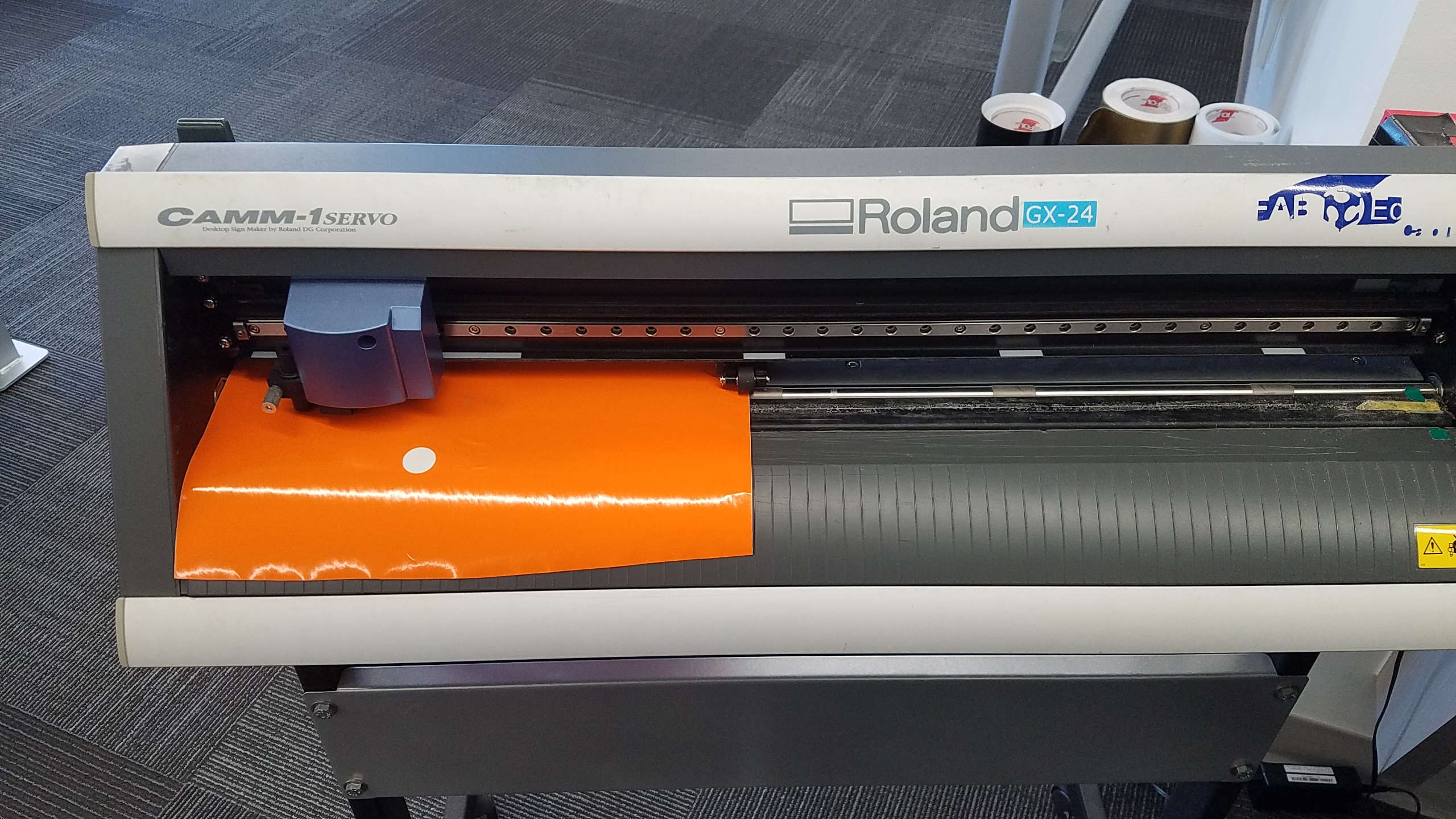
Vinyl Cutter
The Vinyl cutter in ourCPCC Fab Lab is a Roland GX-24.
 Garrett Nelson happened to be in the Fab Lab and was also starting to work on the Vinyl cutter at the same time, so we worked together.
First we addressed the cutter itself:
- Found a video that went through the setup https://youtu.be/8oCOzy_Zx2o
- Press Menu Twice
- Unsetup should be viewed on the LCD Display
- Press the Down button
- Press Right button
- Force was set to 130gf
- Right button to change
- UP and DOWN buttons to increase and decrease
- Changed the force to 120gf
- Pressed Enter to save the setting
- Pressed the down button and Speed was shown
- Right button to change.
- Then Up and Down buttons increased and decreased speed
- Video said range was usually 18 - 20 cm/s
- Our setting was 9 cm/s. We left this setting alone.
Testing
*The vinyl must be up against the left wall of the cutter.
 * Release the rollers by lifting up on the rear left handle
* The rollers must be in the white areas.
* You can “Jog” the cutter head, by using the Left and Right buttons
* To test, press and hold the TEST button until the cutter starts.
* Cuts a circle with a square in it. This is a built-in figure.
* The test was not good.
* Release the rollers by lifting up on the rear left handle
* The rollers must be in the white areas.
* You can “Jog” the cutter head, by using the Left and Right buttons
* To test, press and hold the TEST button until the cutter starts.
* Cuts a circle with a square in it. This is a built-in figure.
* The test was not good.
* If a finger was run across the cut vinyl, you could feel the vinyl was not cut cleanly, but had ragged edges.
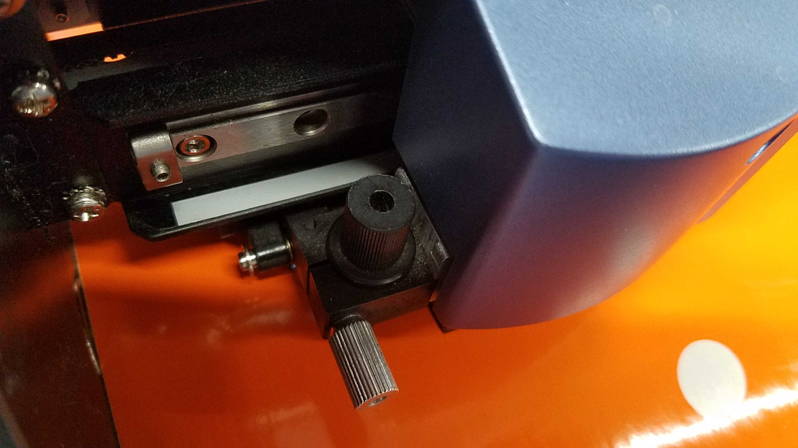
* We adjusted the tool, but felt for a valid test we should work with a new cutter.
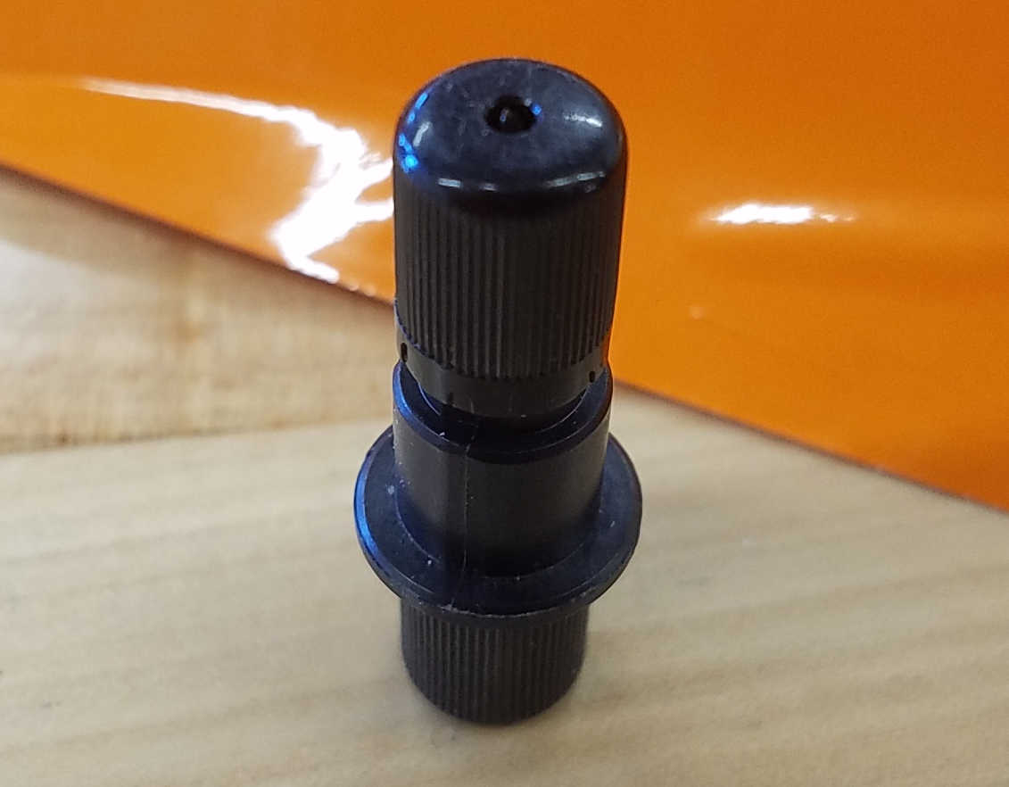 * A new cutter was installed in the holder and adjusted until the holder held solid against a vinyl scrap and it should cut the vinyl cleanly but NOT cut the back plastic. ( A label was put on the machine stating that a new cutter was installed and the date).
* The new test was successful with the circle being able to be removed from the backing.
* An object was then attempted to be printed from Inkscape.
* A new cutter was installed in the holder and adjusted until the holder held solid against a vinyl scrap and it should cut the vinyl cleanly but NOT cut the back plastic. ( A label was put on the machine stating that a new cutter was installed and the date).
* The new test was successful with the circle being able to be removed from the backing.
* An object was then attempted to be printed from Inkscape.
 * The cutter head was jogged to the left side
* The Origin button was pushed to set the machine reference to that position.
* When the print was executed, the Vinyl Cutter just started spewing out the vinyl, and slowly moved to the right.
* The pause button was quickly pushed.
* Upon a guess, the units was checked for the Cutter and the Inkscape. Yep, Cutter was mm and Inkscape was inches!
* Once this was corrected (both set to mm), it was noticed that no cutting was happening.
* From the video, the color must be set to red, and width must be 0.5mm.
* It then printed correctly.
* The cutter head was jogged to the left side
* The Origin button was pushed to set the machine reference to that position.
* When the print was executed, the Vinyl Cutter just started spewing out the vinyl, and slowly moved to the right.
* The pause button was quickly pushed.
* Upon a guess, the units was checked for the Cutter and the Inkscape. Yep, Cutter was mm and Inkscape was inches!
* Once this was corrected (both set to mm), it was noticed that no cutting was happening.
* From the video, the color must be set to red, and width must be 0.5mm.
* It then printed correctly.

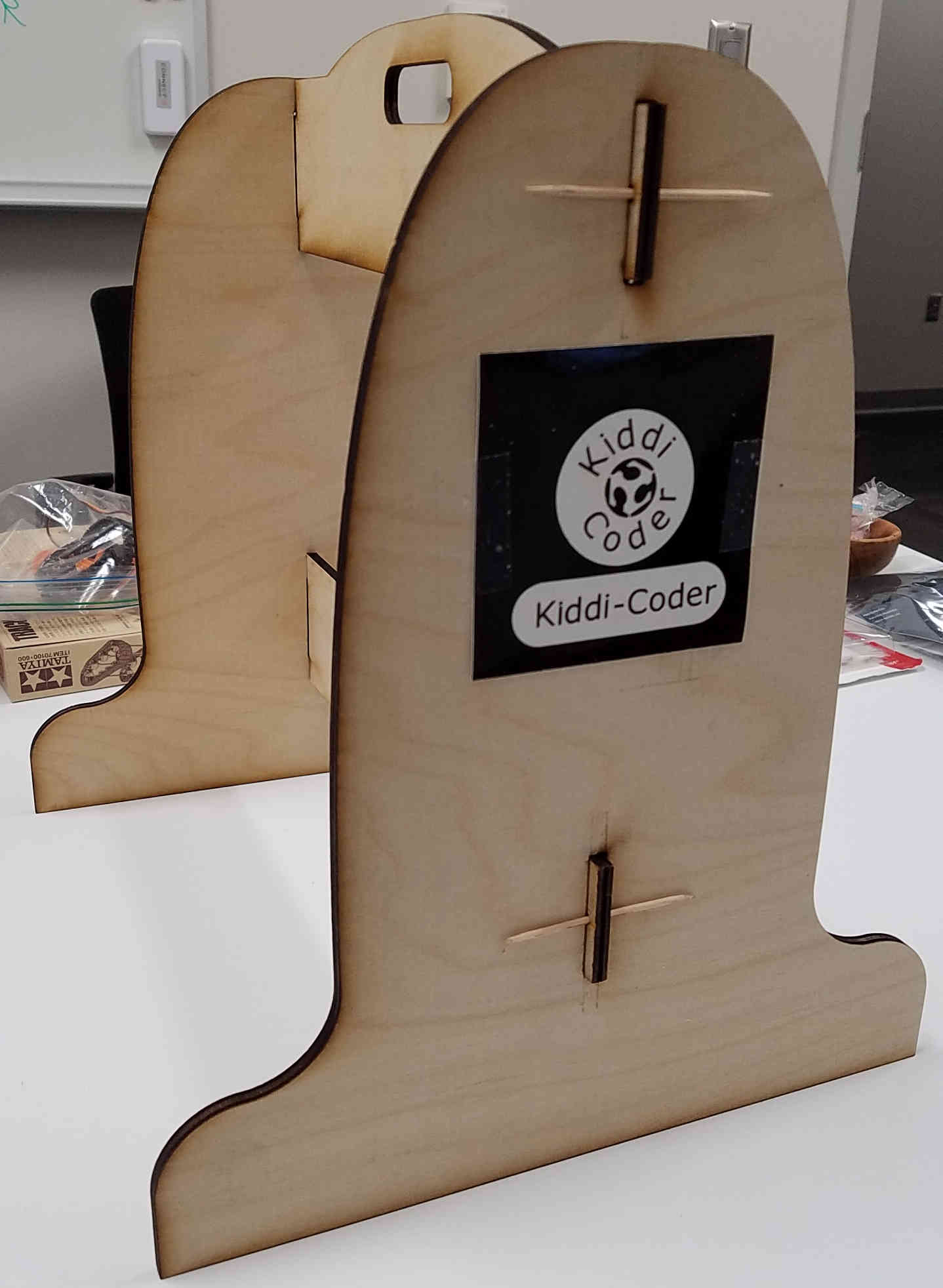
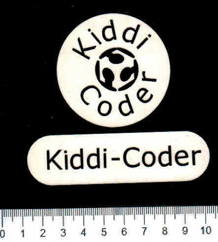
Creating Vinyl Objects for the Final Project: Kiddi-Coder
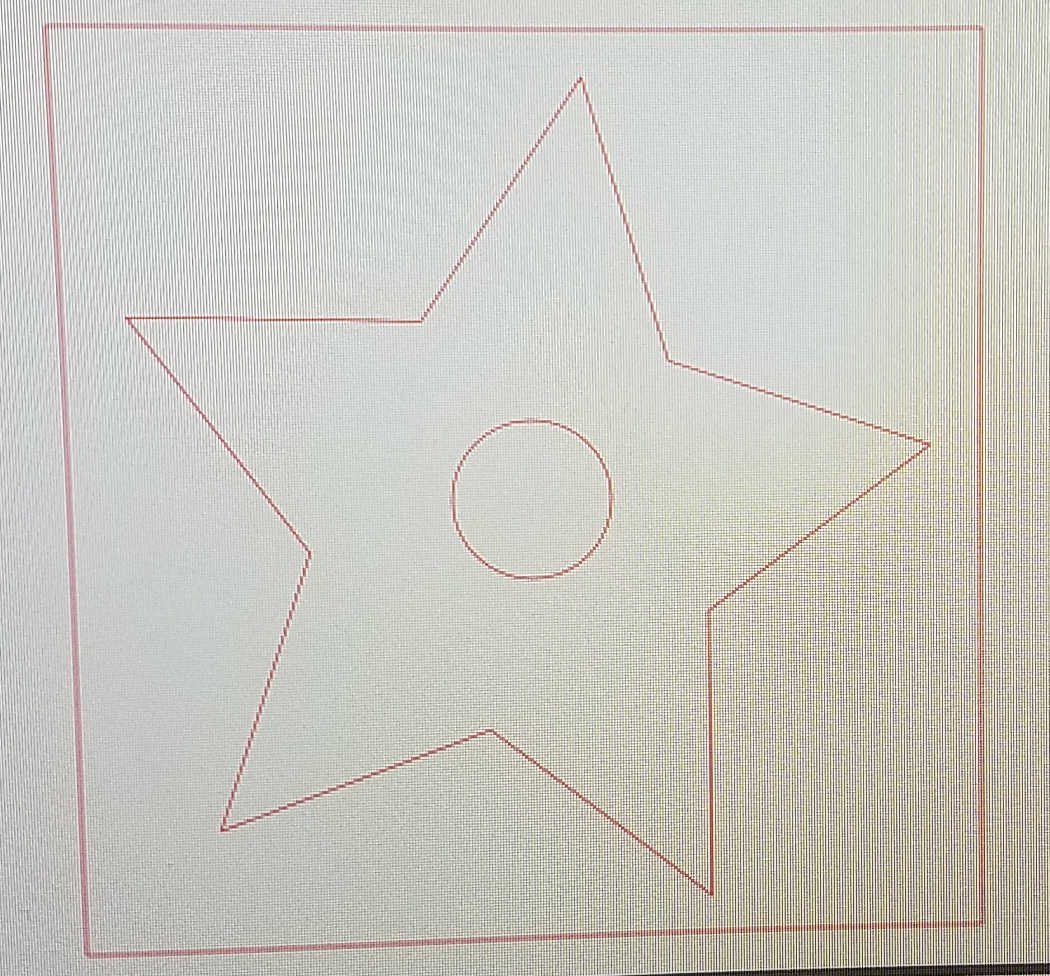
Using Inkscape created a circular Kiddi-Coder emblem
- Used the following website to help to create the circular emblem:
https://daviesmediadesign.com/how-to-wrap-text-around-a-circle-in-inkscape/ - The text was made red, no fill, and 0.5mm stroke thickness.
- I had to use two circles, one smaller one for the outside top, and a larger one for the bottom text, on the inside.
- The bottom text “Coder” had to be spaced out to make it look correct. The circles were then made green to not print.
(But the green still printed. Had to make them transparent, to not print)

- A larger red circle was placed co-centric, to have the entire emblem removable.
- A single line with an oval around it was also generated.

- Both were then cut on the Vinyl Cutter.


The emblem was too large
- A smaller version was then designed and Vinyl Cut.
CAD project using Fusion 360
I previously had Fusion 360 from AutoCAD installed, The license had run out, and I had to relicense the educational copy.
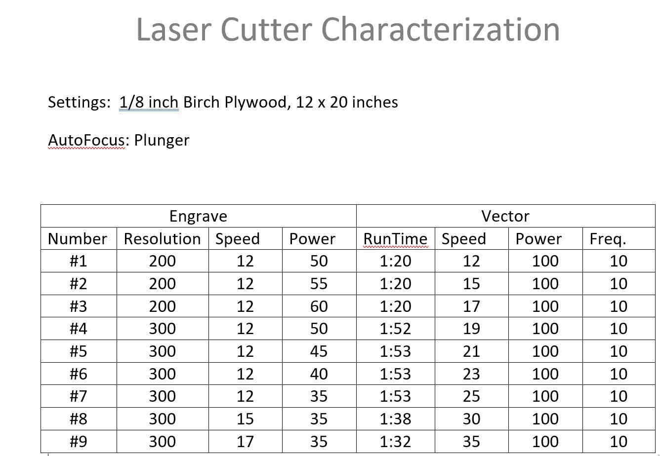
Characterizing the Laser Cutter
Our Fab Lab has the Fusion Pro 36 Laser Cutter
Research
Watched a Youtube video on parameters, which explained how to parameterize your drawing using variables. https://www.youtube.com/watch?v=3GQHaYdmULs
Thought as an example I could use, is to create the plywood sides of my Final Project (Kiddi-Coder), but use a parameter for the thickness, so the insert holes would adjust, for the thickness of the plywood. I could set the thickness to cardboard, and using the laser cutter could cut out a model using cardboard.
Designing with Parametric Parameters
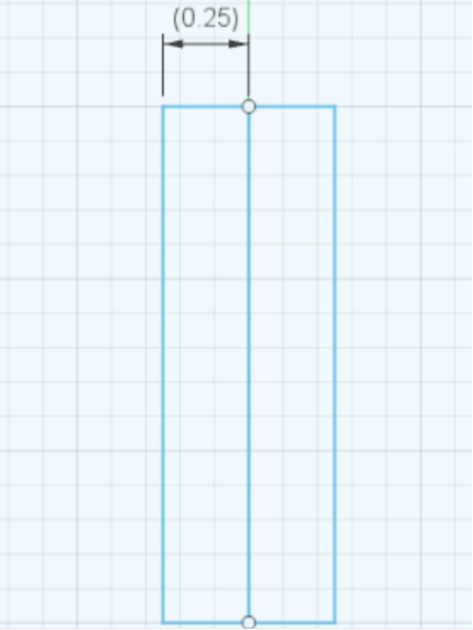
The slot parameterization was difficult. I first selected the overall width as FrameThickness, but it would not stay centered as the dimension changed. I initially had set the FrameThickness as 0.5 inches and half of the width would be 0.25 inches, but the origin of the change would be on the Left, and the hole centerline location would change as the dimension varied. The solution was to make the two top segments constrained using the equal constraint.
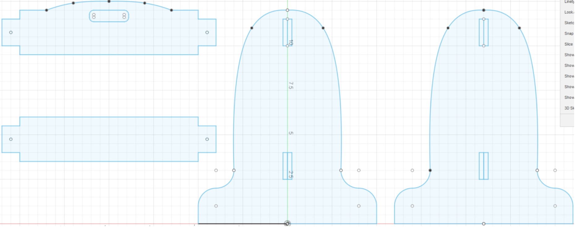
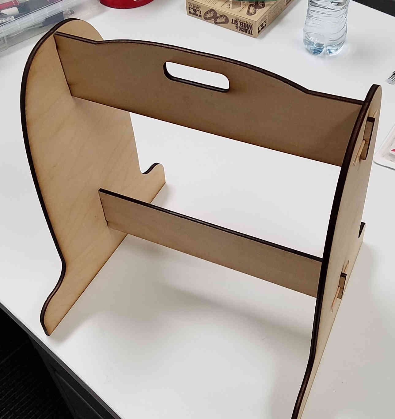
The parameter controlling the objects is FrameThickness. As that parameter is changed, the thickness of the plywood changes and the slots in the side pieces also change.
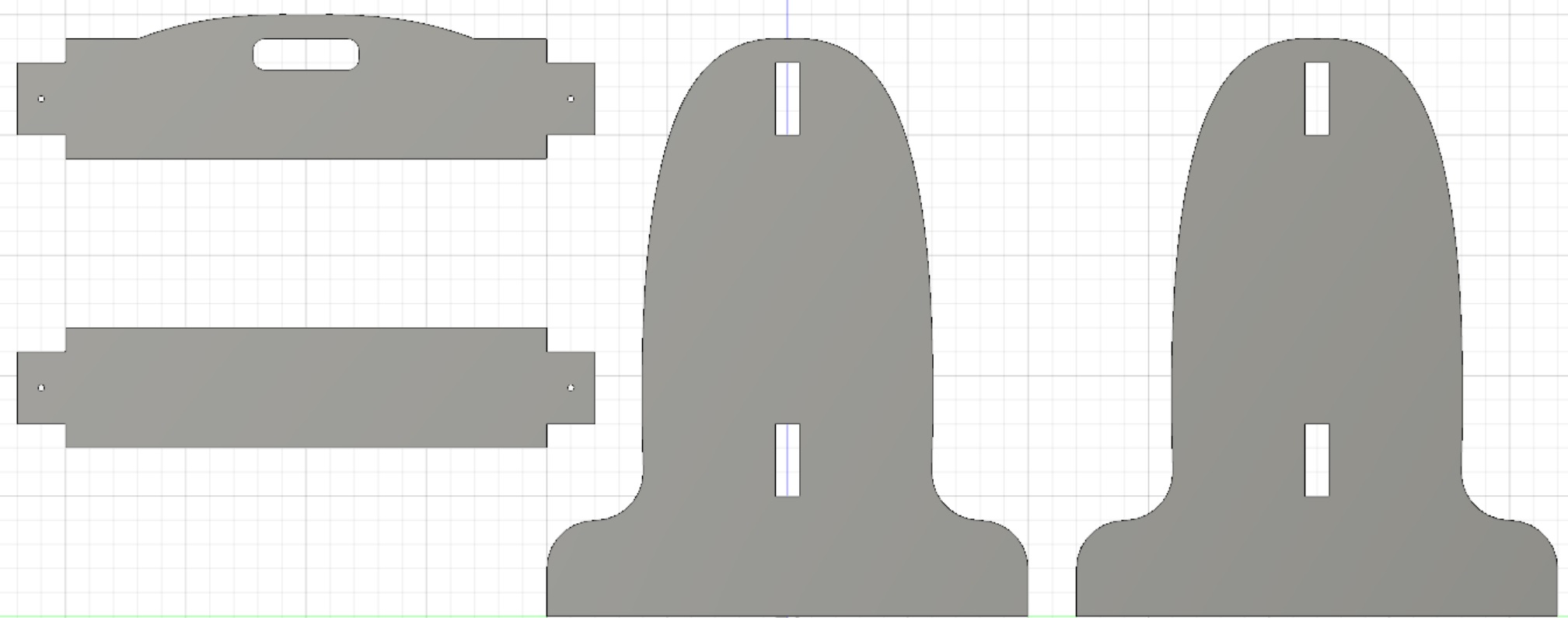
Thus the above layout was obtained as I extruded the objects out using the FrameThickness parametric variable, which was set to 0.5 inches.
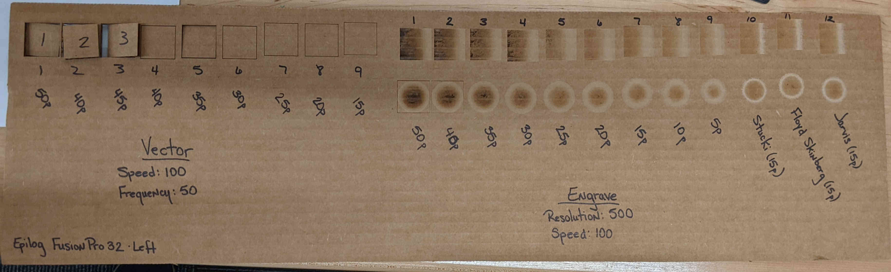
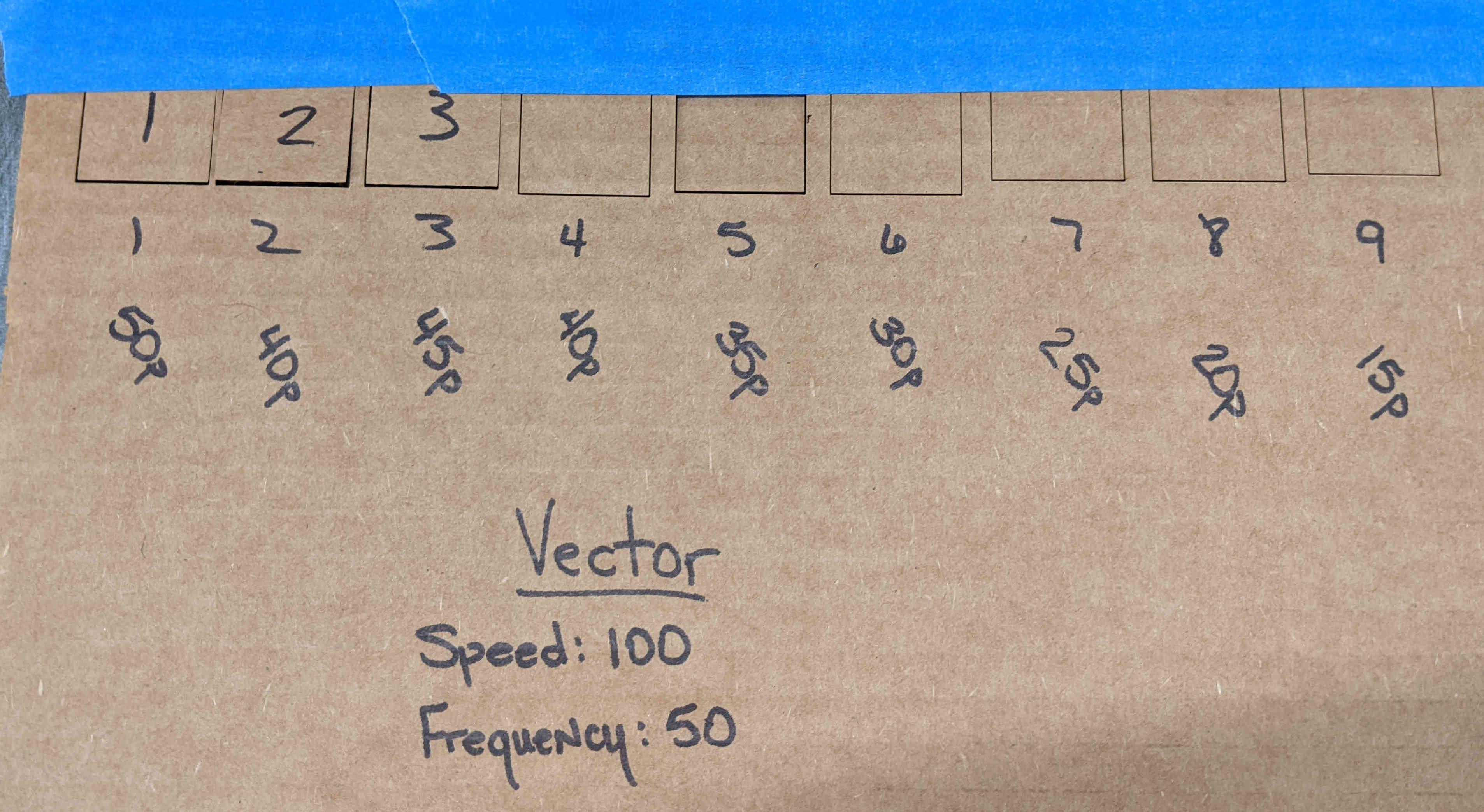
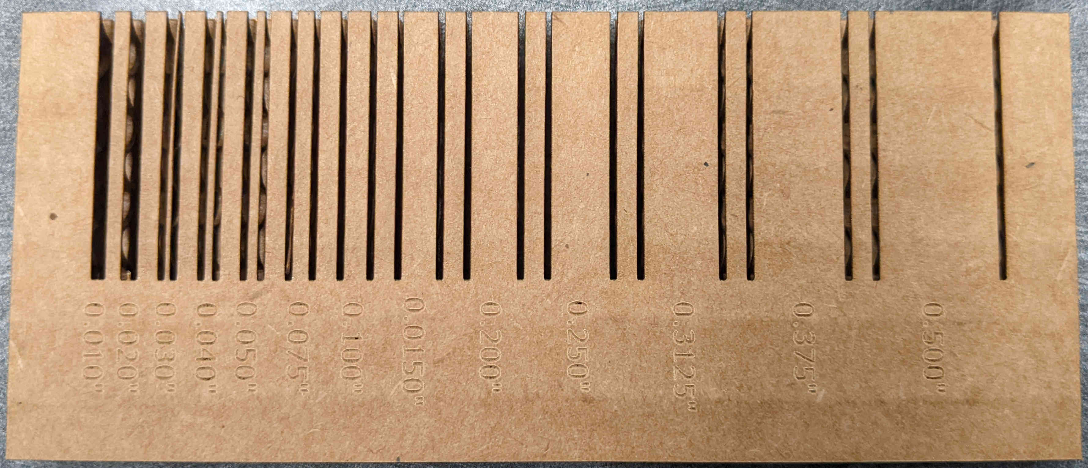
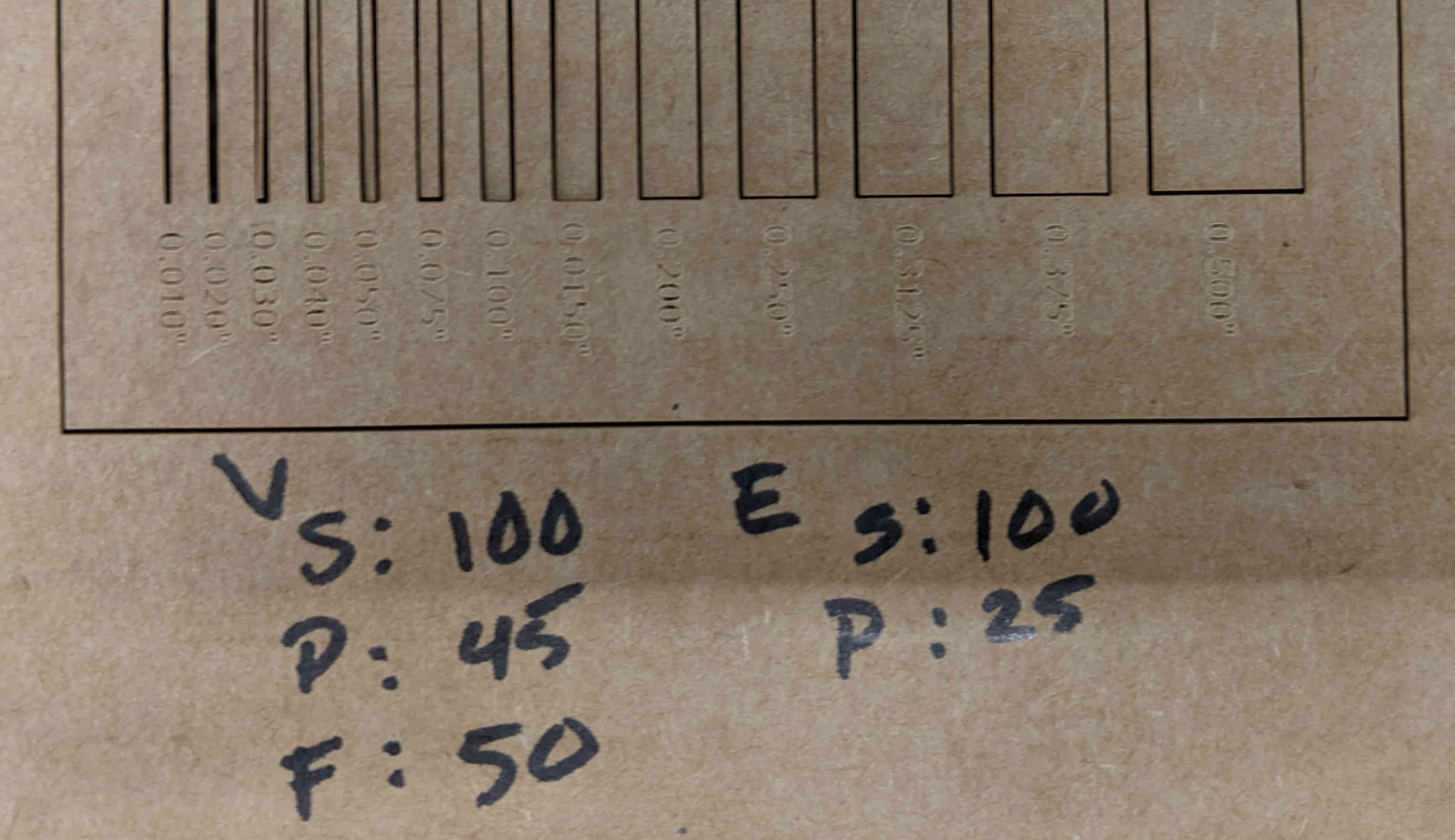
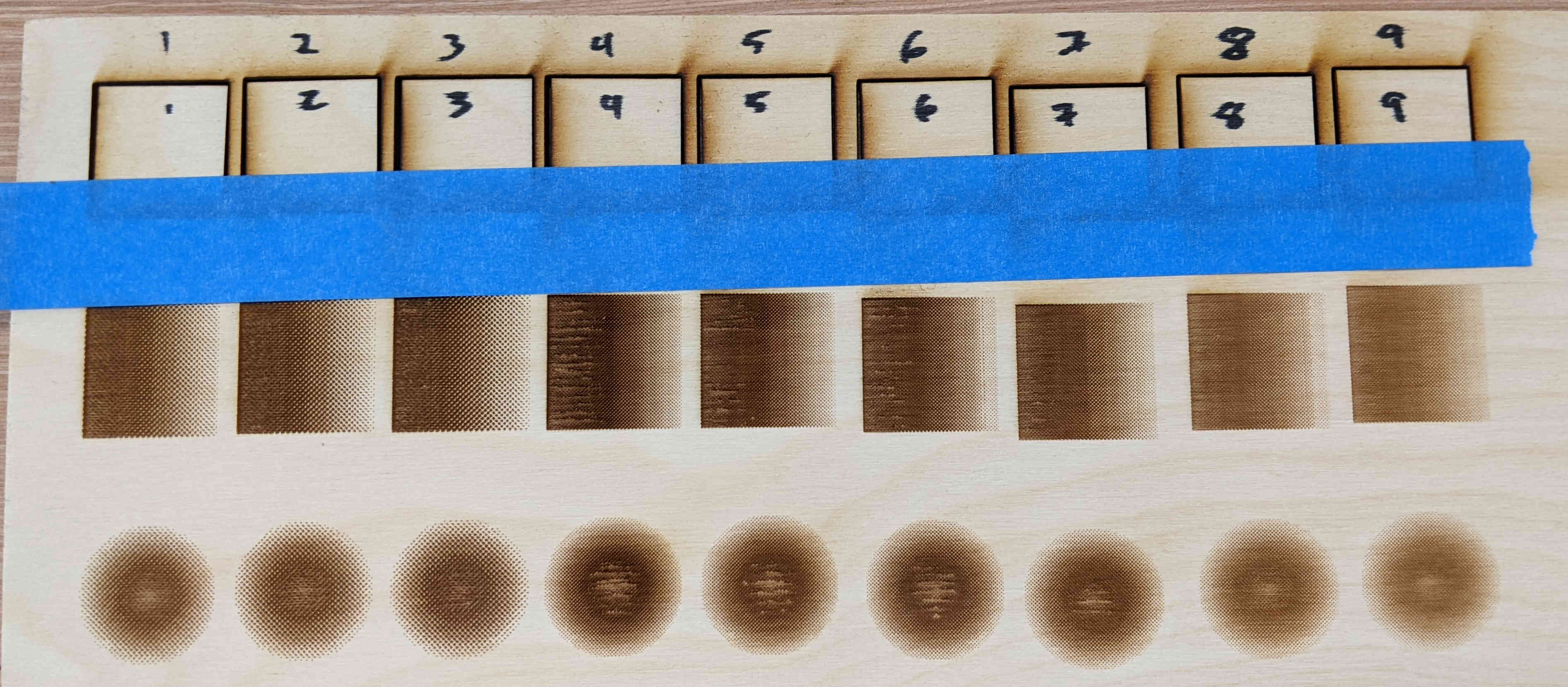
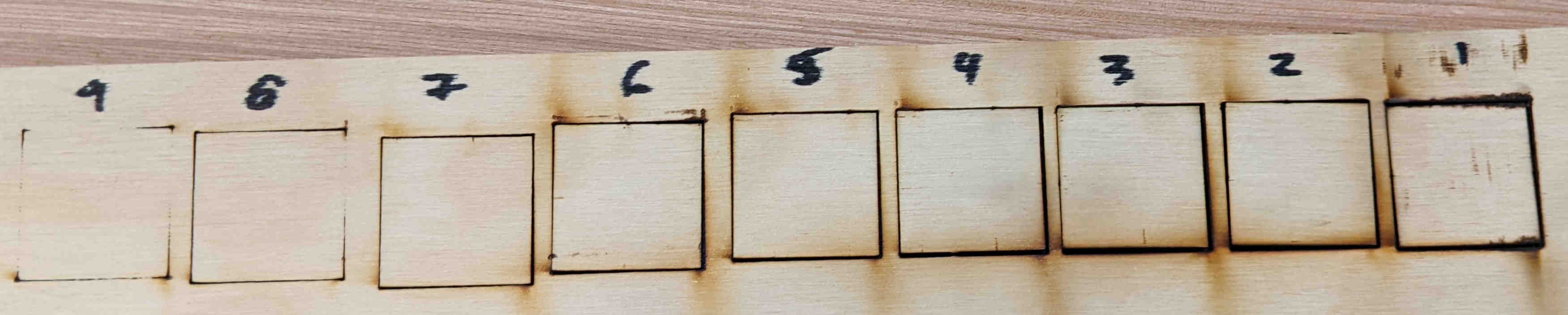
Analyzing the Laser Cutter
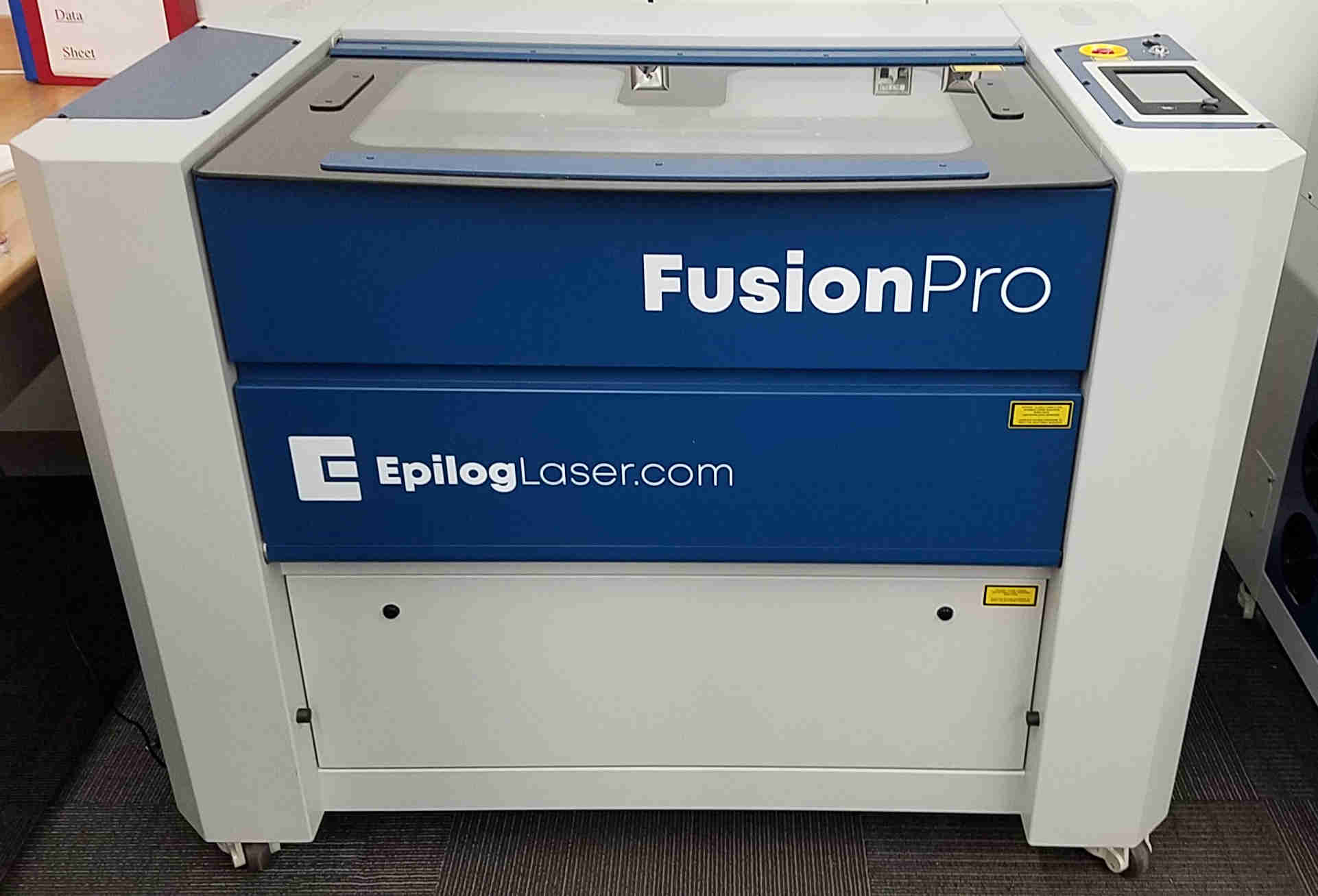
Our lab has the above Fusion Pro 32, 120 watt Laser. The following images were taken as different cuts were made.
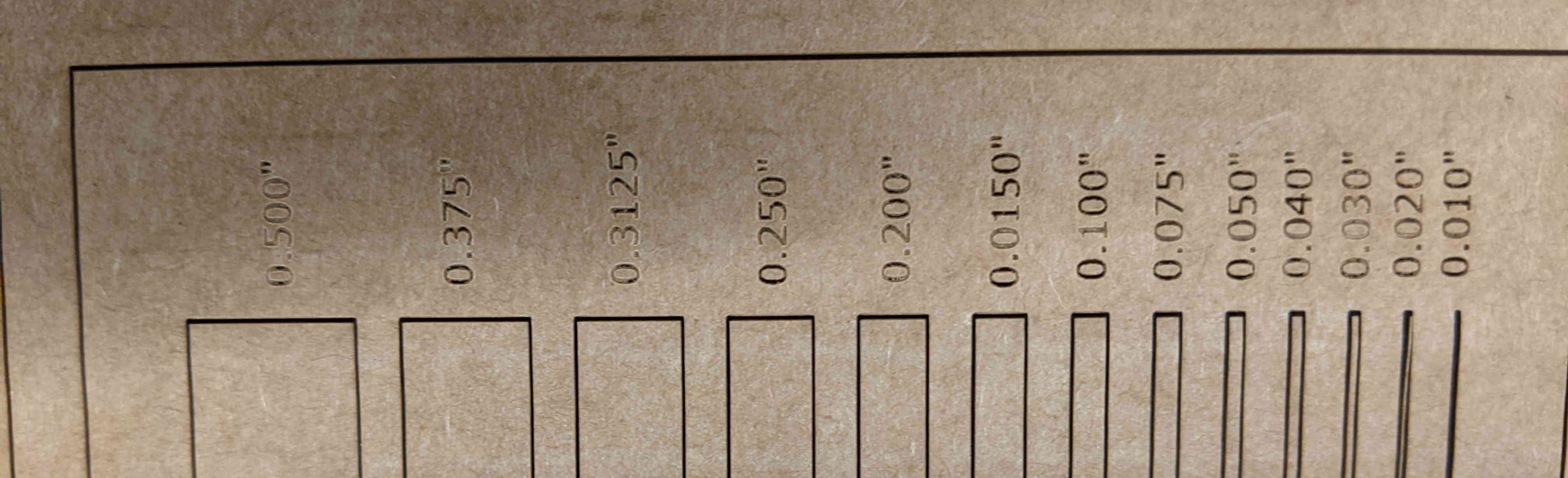
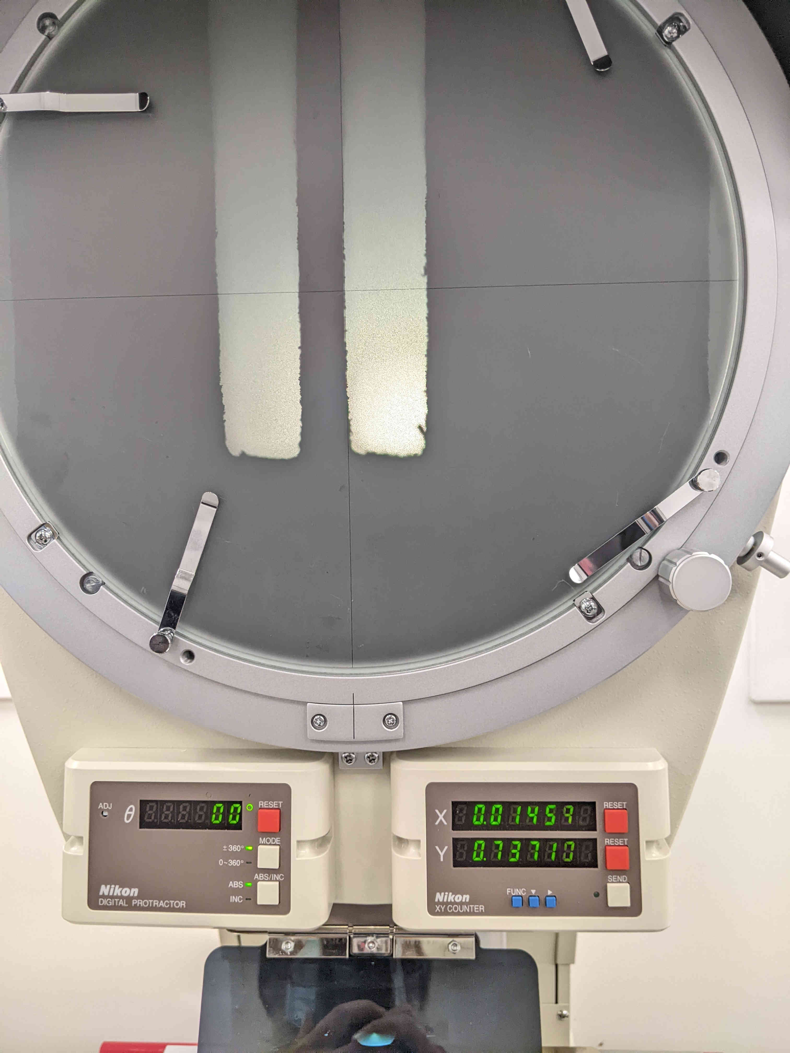
This is the optical measurement tool that is in the CPCC CNC Lab
Finally cutting out the reduced size frame for the final project
 Adding the Kiddi-Coder Emblem