4. Computer-Controlled cutting
Link to this week’s Group Assignment
4.1 Nature and children as inspiration for computer-controlled cutting
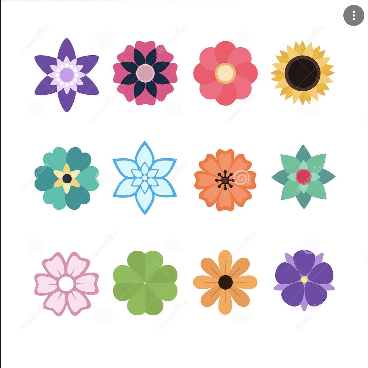
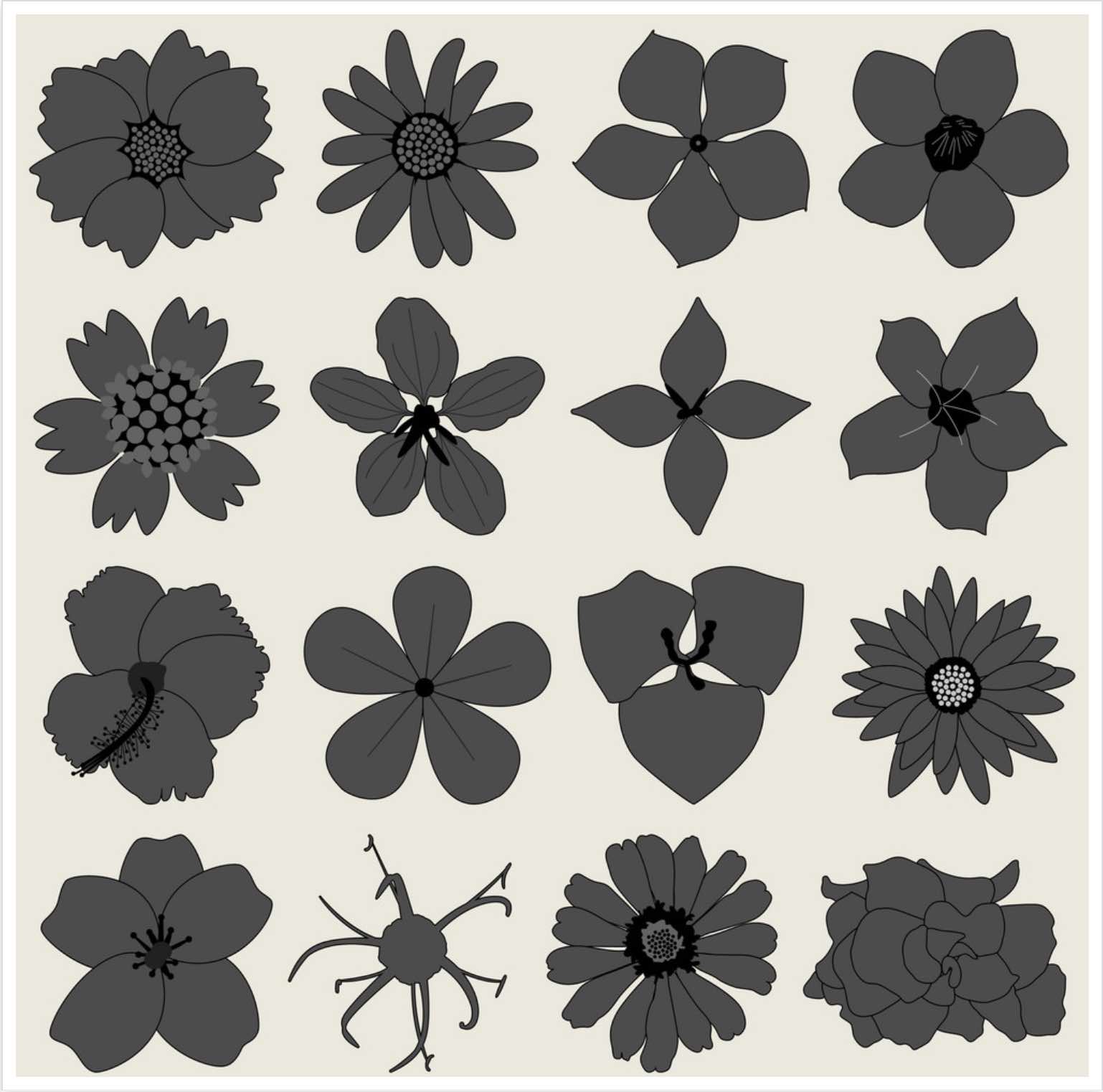
4.1.1 Petal Typology
To me, flowers are nature’s highest form of expression of beauty and complexity within the plant kingdom. They are divided into specific numbers of sections and proportions, inviting me to investigate the replicability of their shapes and proportions via parametric design on CAD.
My intention this week is to create shapes that match the ones of flowers found in nature.
The inspiration to create a Kumihimo loom comes from being in touch with children who are currently using them for cord making; however, the kids I know seem to only have a four sided loom available. (See image)
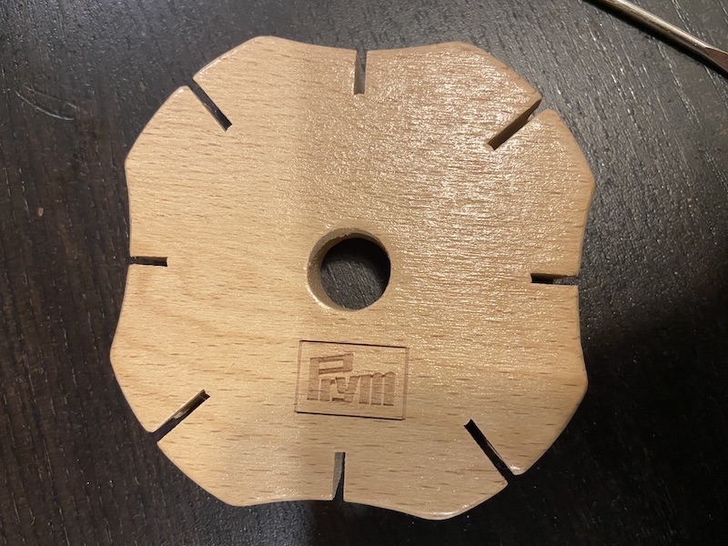
Kumihimo is the traditional Japanese technique of braiding strands of silk to create intricately colored cords.
By creating a set with four variants (for 4, 8, 16 and 32 slots for yarn), the users will have the opportunity to generate weave patterns and, if desired, also use a broader colour palette.
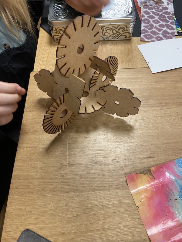
In addition, I am designing for the loom to stand on the unused pieces, creating the shape of a table that would enable the users to have a more consistent tension along the process.
4.2 The importance of parametric design
To open up this section, I will begin by exploring Wikipedia’s definition of ‘parametric design,’ as it happens to be a new concept I need to get acquainted with.
“Parametric design is a design method where features (such as building elements and engineering components) are shaped according to algorithmic processes, in contrast to being designed directly. In this method, parameters and rules determine the relationship between design intent and design response. The term parametric refers to input parameters fed into the algorithms.”
Possibilities for this appear to be endless. Perhaps the best way to measure the advantages is to begin experimenting.
4.2.1 Parametric design construction
The process begins with a simple triangular shape. To this I added a chamfer and kerf, in order to have them projected on all future polygons.

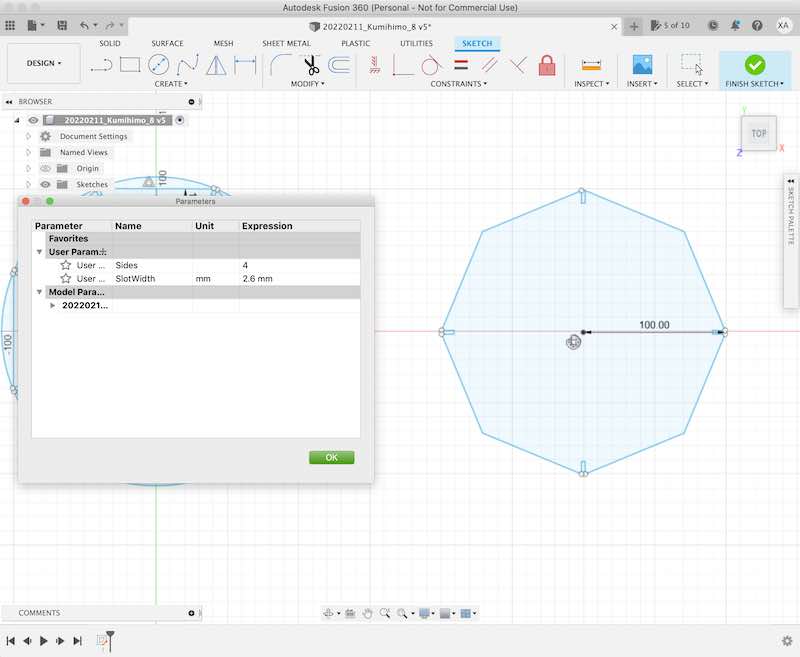
The triangular shape can be adjusted and multiplied as many times as needed by assigning specific parameters.
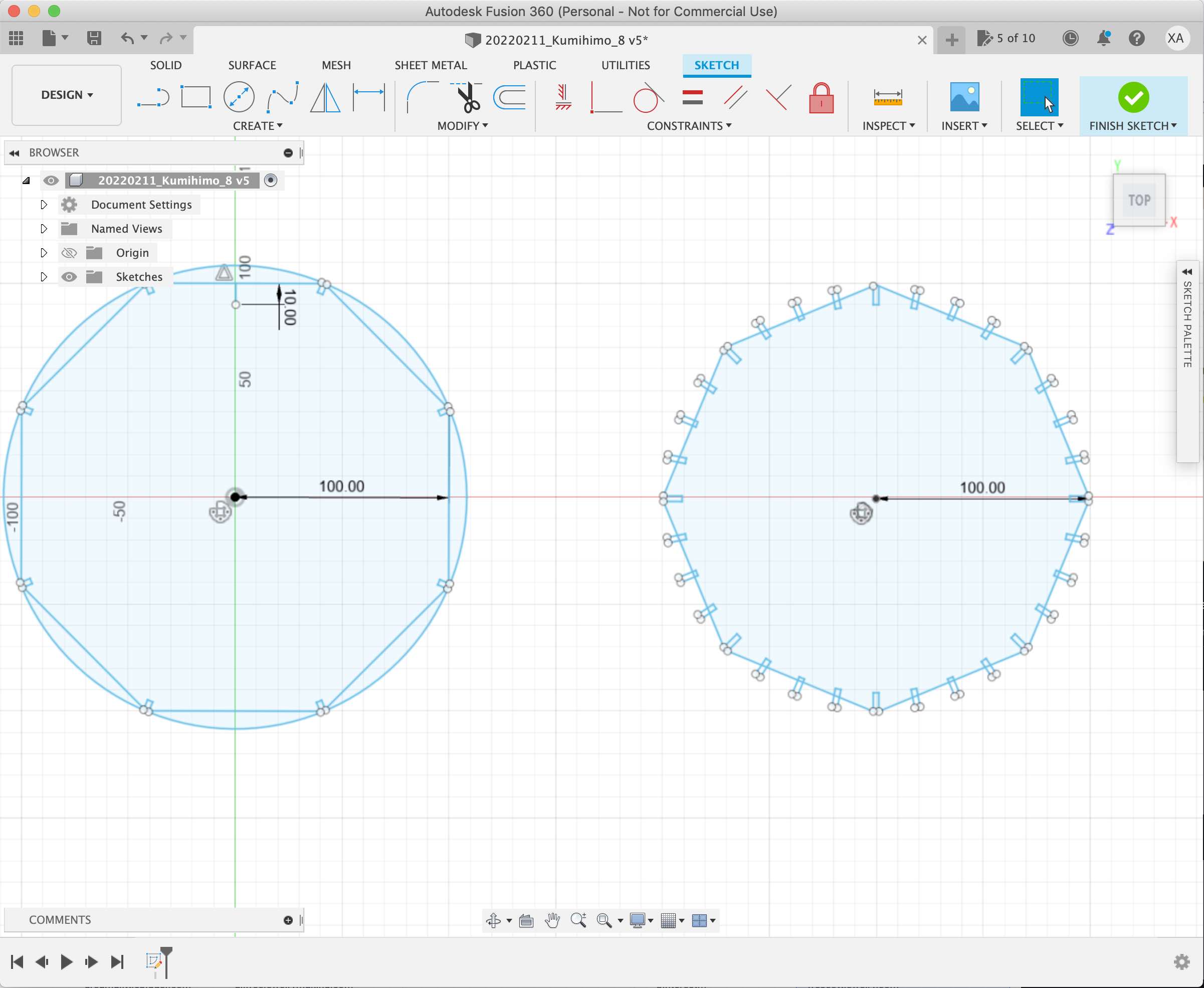
I have decided to double the number of sides and notches for a thread with each new iteration; however, I only covered 4,8,16, and 32, as 64 would require considerably bigger pieces of MDF, and my desire is for the end product to be compact and portable. With that mindset, here is my first proposal of a four-sided loom piece next to the ‘parameter’s’ dialog box.
On this third slide, I present the eight sided version. The polygon on the right is [another] test to be ignored.
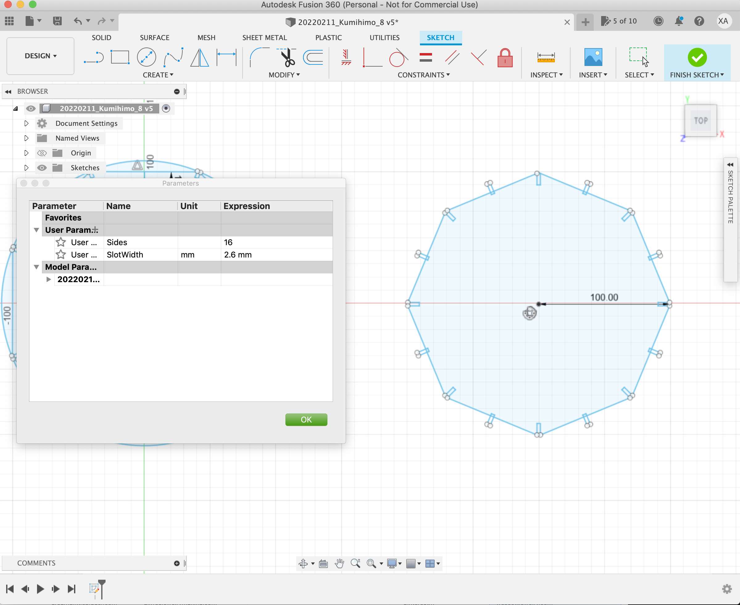
Here is the construction of a 16 side polygon.
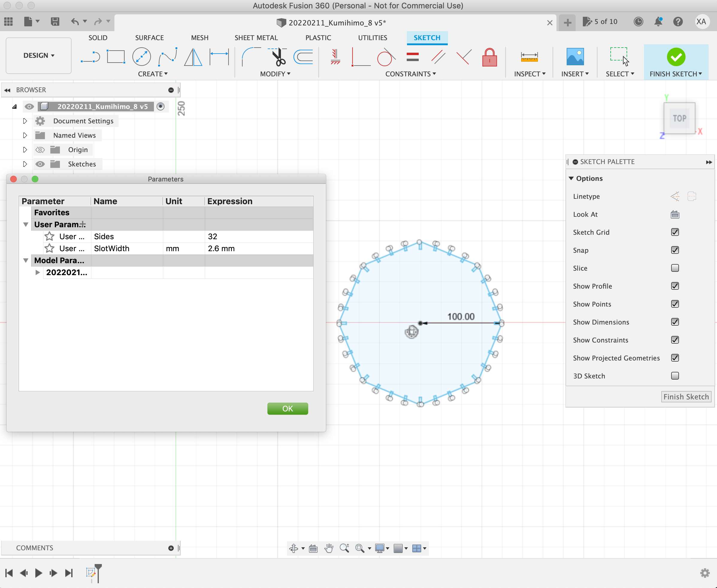
And finally, a 36 side polygon. I still haven’t tried making a cord of such complexity; however, I am sure it is possible and just a matter of time and dedication.
Original filesof the compiled parametric construction ofthe Kumihimo loom set.
Original files of the compiled parametric construction of the Kumihimo loom set readyto be cut.
4.3 Construction of a press-fit kit
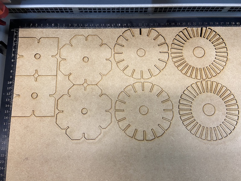
Having created the parametric construction file as well as the different versions of it (4,8,16 & 32 sides); I exported them from Fusion 360 into Rhino — Barcelona FabLab’s default program for communicating with the laser cutter during the last stages of the design process. The main tasks in Rhino are to make sure all curves are joined and set in 2D.
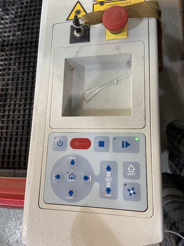
The next step is to use “Job Control” software to work with the laser cutter. Once the file is ready to be cut, the colors in the system are there to determine if the job will be cut or engraved, (by following the order in which the colors are listed). At this stage, pecific colors need to be chosen and assigned for the job needed.
The right speed, power and frequency are to specified based on the material and its thickness. In this case I chose MDF, therefore set the parameters as follows: power at 50% and speed at 0.5% — since the laser lens appears to be in good condition.
Specs for the Fablab BCN laser cutters:
Manufacturer: Trotec
Power: 100 watts
Power range: 0-100
Max speed:
Speed range: 0-1
Kerf: 0.15 mm
Frequency range: 0 - 20,0000

Bed size small format machine:
Bed size large format machine: 300 x 600 mm
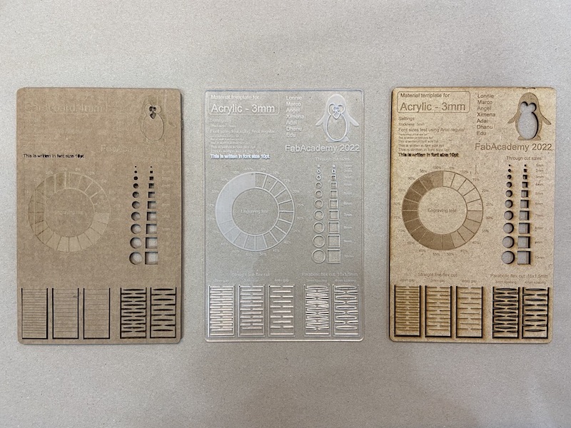
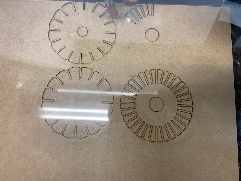
The laser cut pieces of cardboard, acrylic and MDF are part of our group project and serve as a reference guide to gauge the right parameters for each job.
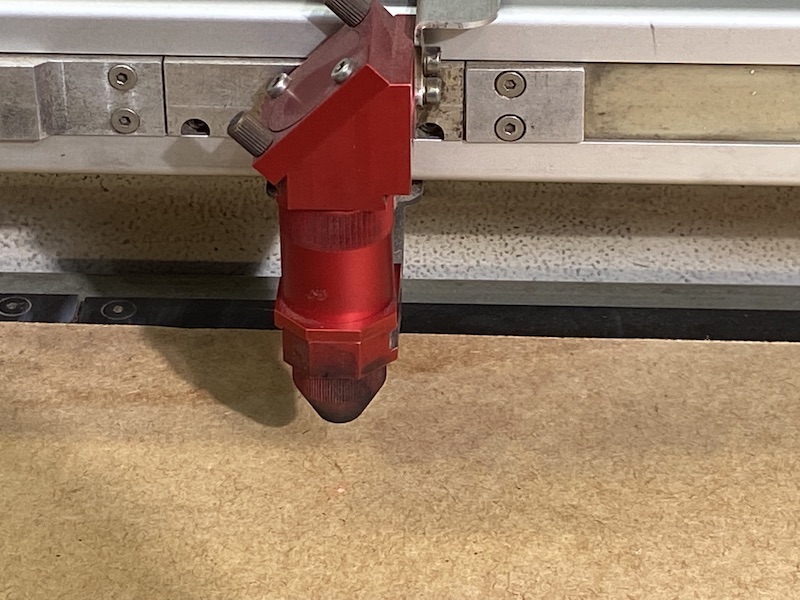
The ‘x’ and ‘y’ need to be located to assign the origin from which the machine will begin to cut. The tool on the image below is th one used to adjust the ‘z’ and focus the laser beam, making sure it works in optimum conditions each time. The ‘z’ should be adjusted at each and every job.
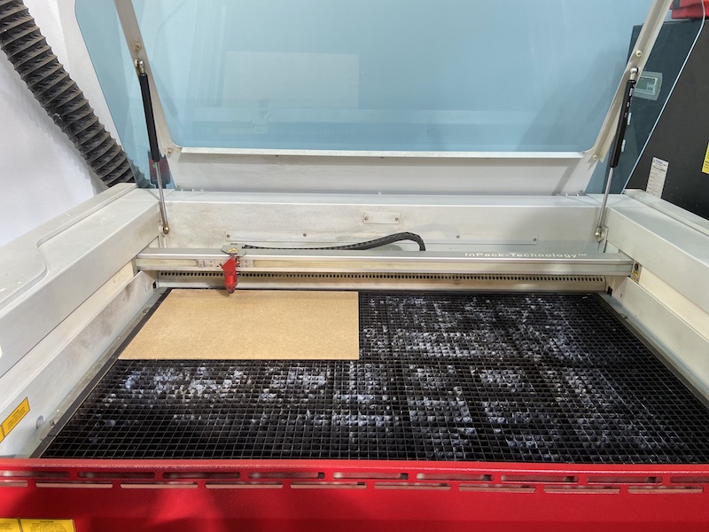
In the next following two images is possible ot see the laser having been adjusted. Generally, before a file is processed, a small square of 5mm x 5mm of material should be cut off in order to confirm the correct functioning of the assigned parameters.
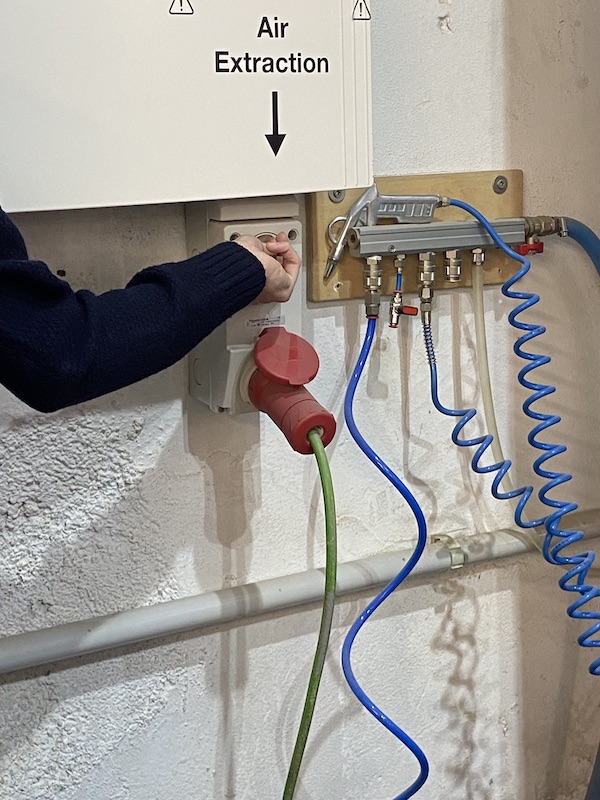
Last, but not least, the air extractor needs to be run prior to the machine, to avoid inhaling toxic fumes and help prevent the laser cutter and job from catching fire.
Video of the laser cut of the Kumihimo set.
4.3.2 ‘Hero shots’ of the Kumihimo loom set.
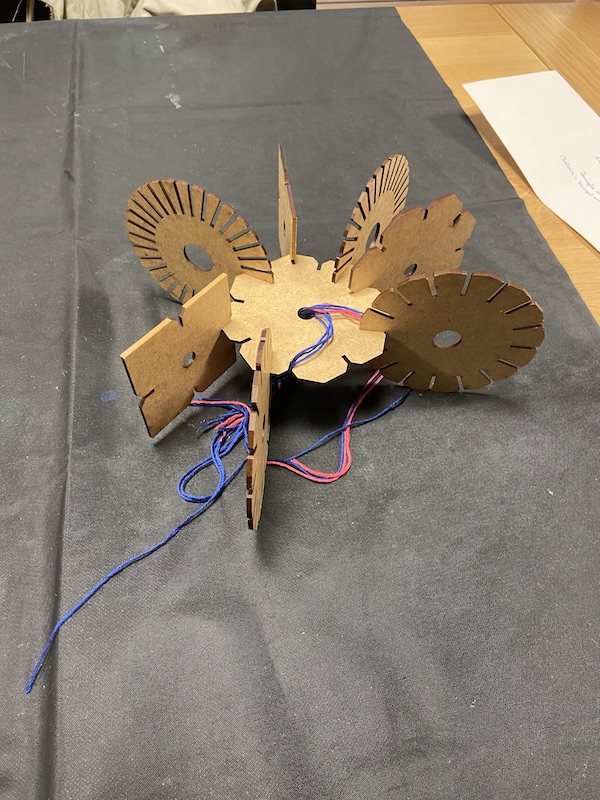
Video of the Kumihimo loom in action
4.4 Vinyl cutting procedure and example
In order to avoid wasting “precious materials” (A.K.A. plastic) I have decided to make a small vinyl cut-out of the logo of a collective bookbinding workshop I have been taking part on for the last decade in a city library.
My wish is to add this small experience to the array of possibilities in which a logo can be used and for the exploration of its characteristics and to gather knowledge on how to interweave the need to respect an existing visual identity and the possibilities given by this technique.
On the first image the logo appears nn Inkscape in my computer. This is the first time I use this software adn I am quite excited to finally have an open source alternative to the Adobe package programs.
In the left screen, the same logo has been exported form Inkscape and can be seen being prepared with Silhouette Studio program — the default software for the Silhouette Cameo vinyl cutter.
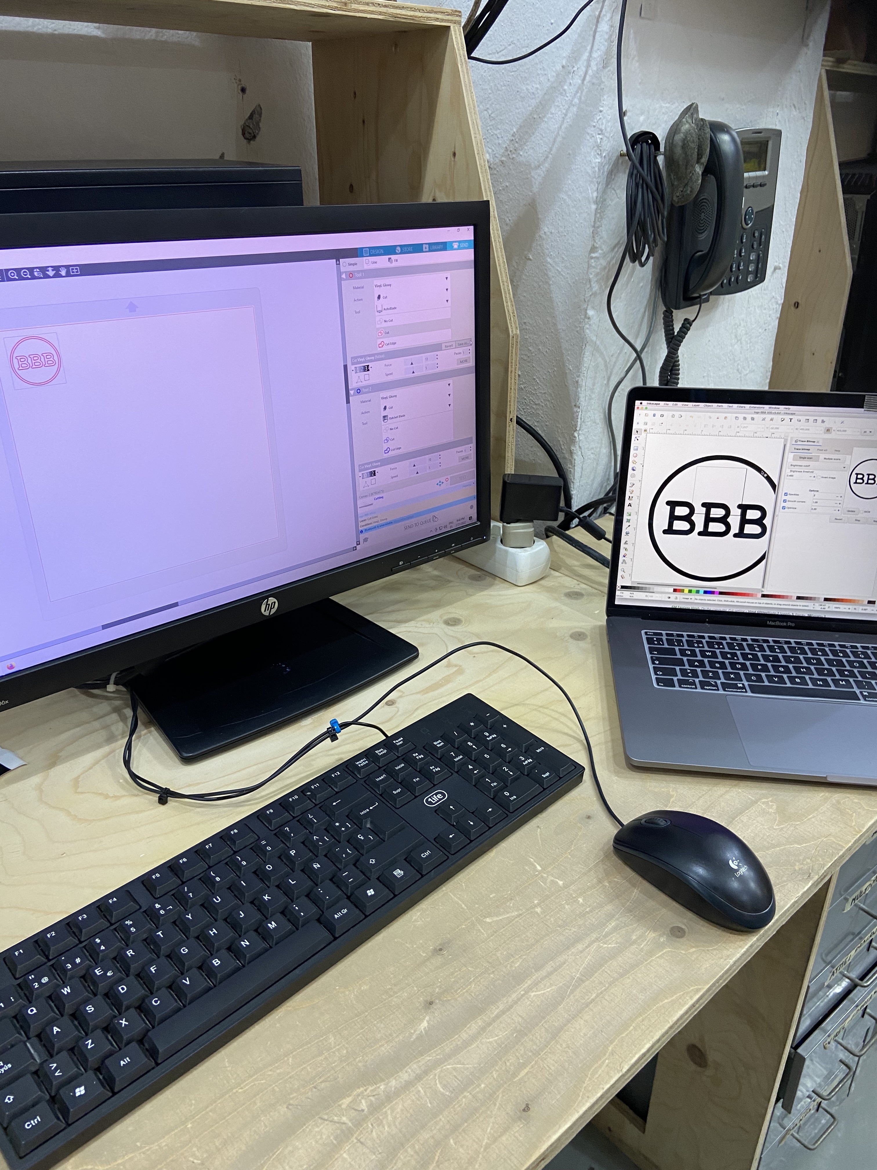
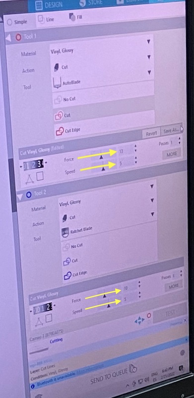
Once the file is ready, the depth of the cut is tested and with that, the vinyl cutter is set to work. Please see below a detail of Silhouette Cameo’s software UI interface, showing the specific settings for this job.
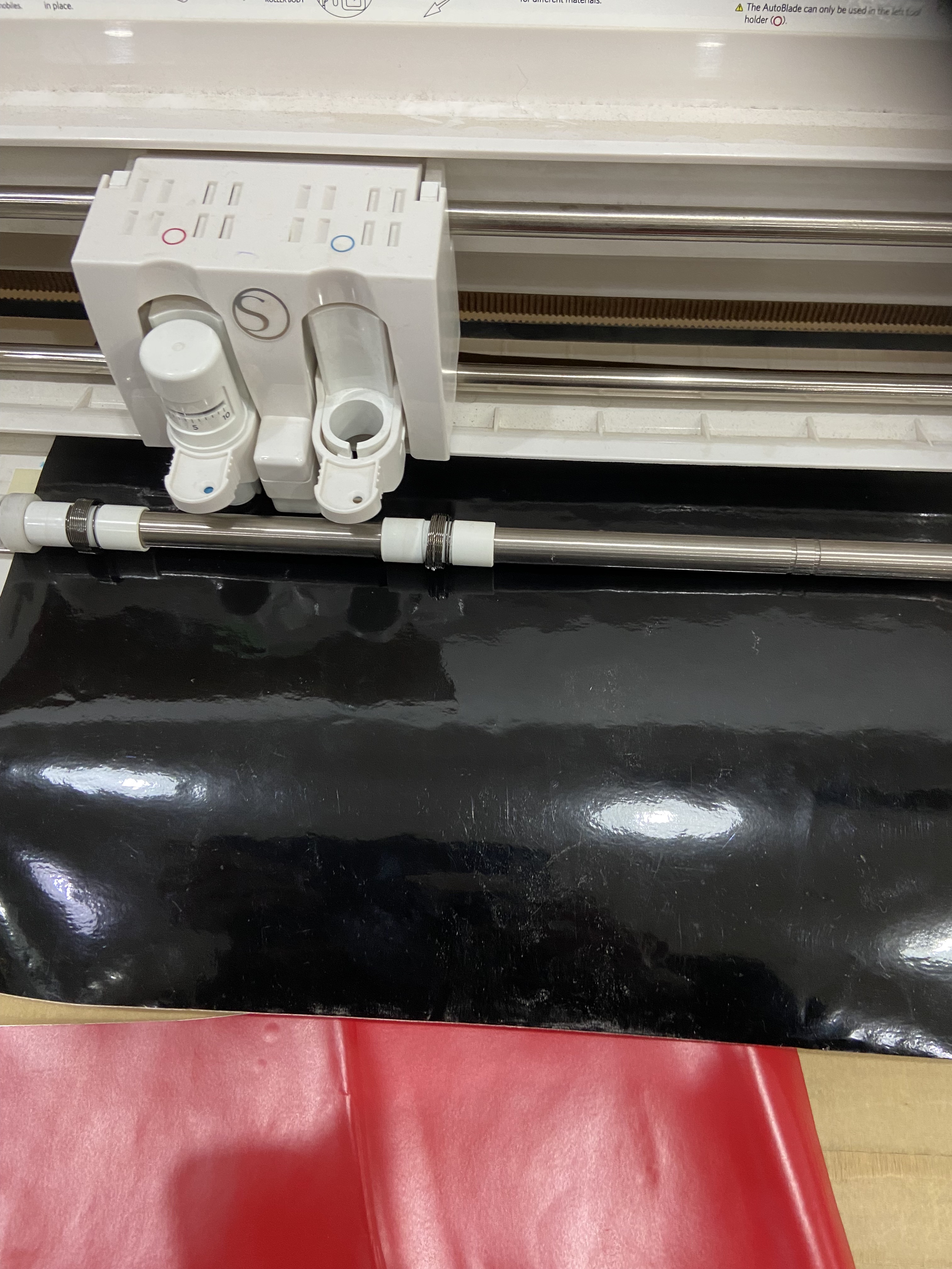
My initial intention was to cut out of red vinyl, since the logo is originally red on white. However, after many attempts similar to the one shown (see image below), I learned about the important role that the size of the vinyl piece plays: the smaller the piece, the more difficult for the machine to hold in place, therefore producing [consistent] unsatisfactory results.
In order to be able to finish the exercise, I chose a random vinyl color and went ahead with cutting.
In the image below is possible to see the cut-out already glued to my computer case. In order to fully cover the machine’s logo, I went ahead and cut-out a red vinyl circle to serve as background for the black logo. To the right of the piece lays a piece of used black vinyl with the missing parts showing in white.
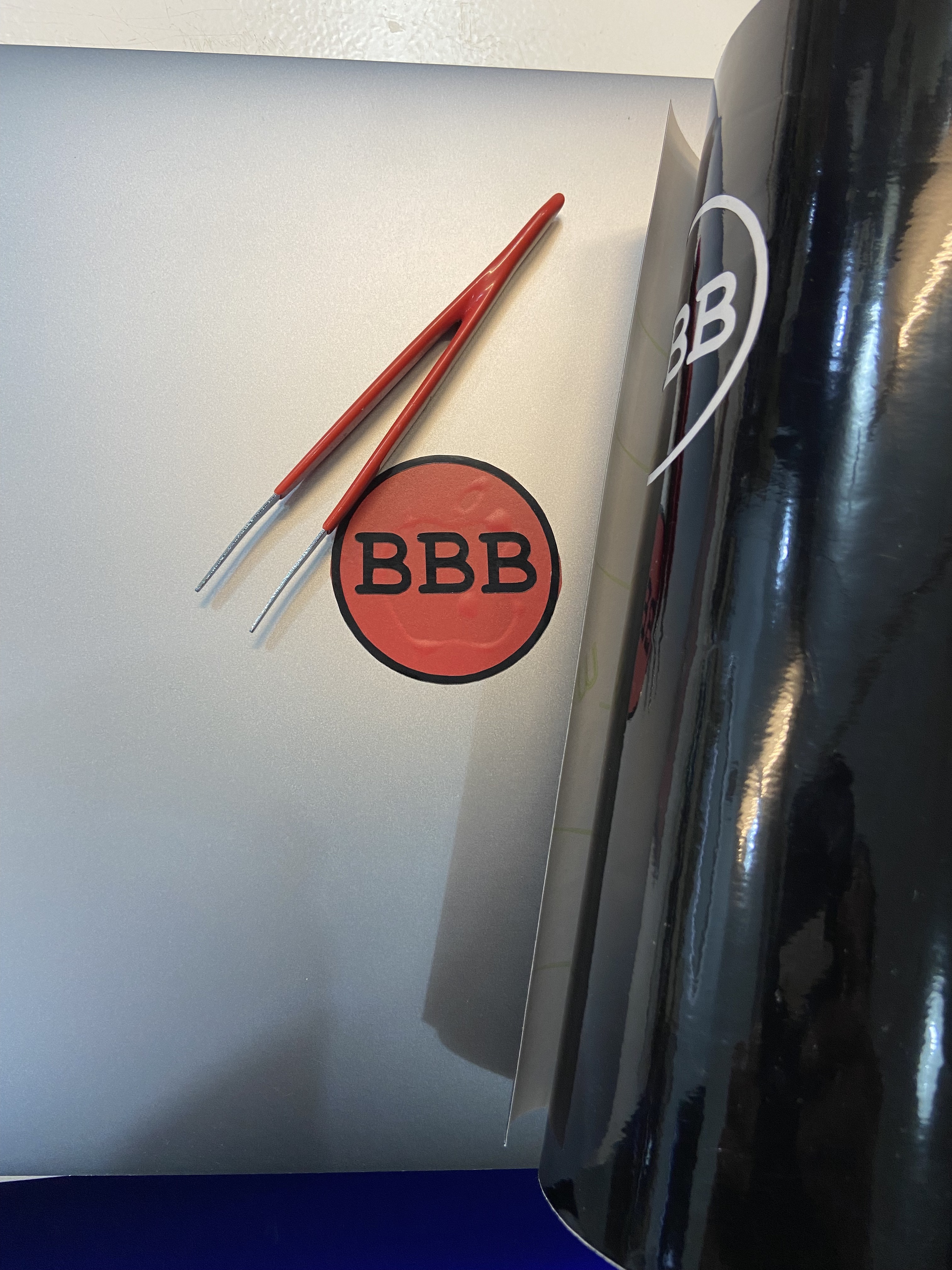
Original files of the BBB vinyl cut logo.
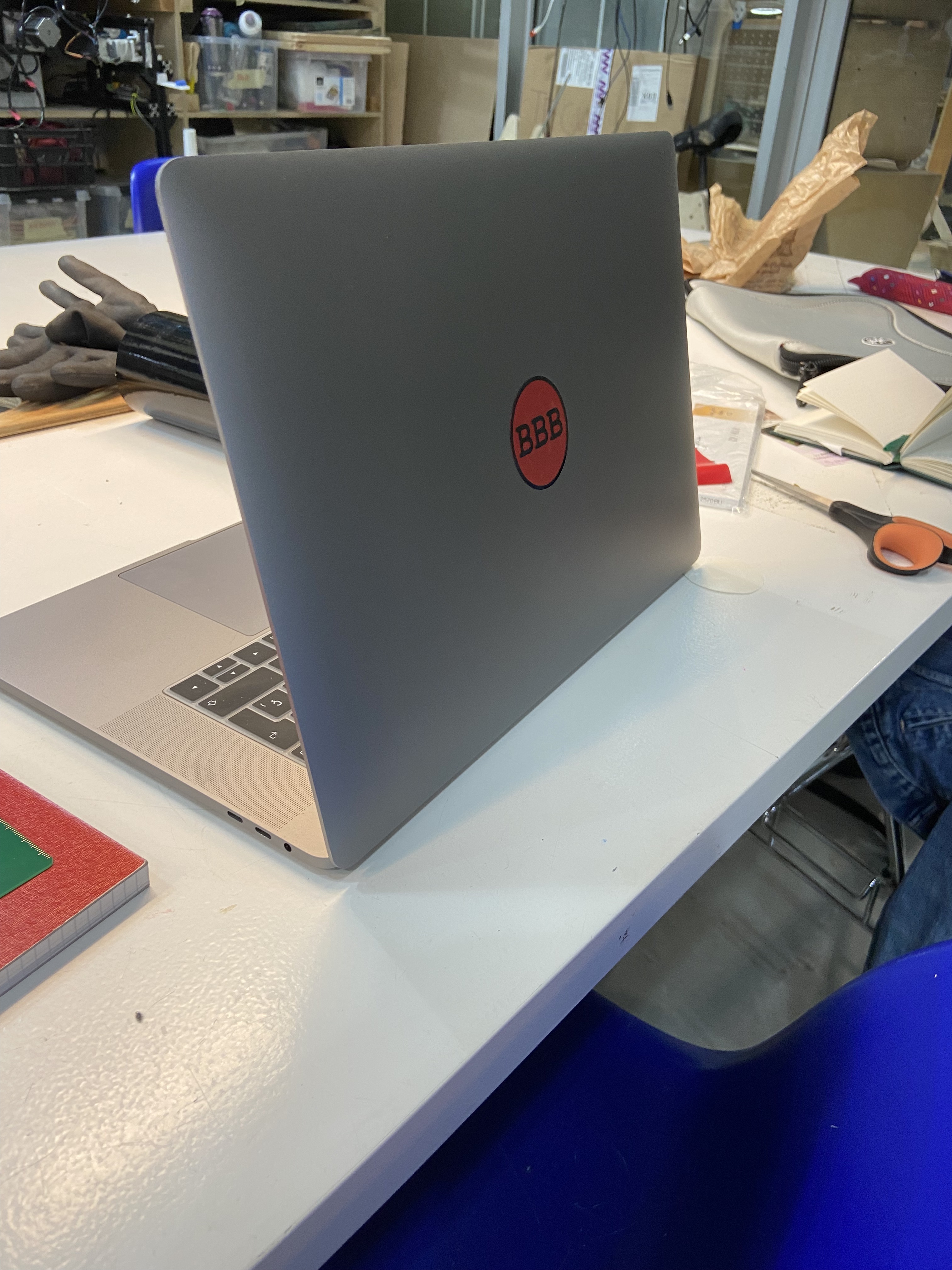
See below a ‘hero shoot’ of the final product.
Resources
- Jabi, Wassim. Parametric Design for Architecture. Laurence King,London 2013.
- Woodbury, Robert. Elements of Parametric Design. Routledge, 2010.
- Frazer, John (2016). “Parametric Computation: History and Future”. Architectural Design. 86 (March/April): 18–23.
- Combs, R.A. Kumihimo Basics and Beyond: 24 Braided and Beaded Jewelry Projects on the Kumihimo Disk. Kalmbach Books, 2013.
- Carey, J. Creative Kumihmo Carey Co, 1994.
Useful links
-FabAcademy BCN Local Documentation
-Nueval Computer-Controlled Cutting
-Wikipedia’s of parametric design