5. Electronics production
This week is about learning the different options and processes available to produce PCB’s.
While PCB production through Etching is possible using acidic and alkaline methods, due to leftover hazardous waste, this process is mostly reserved for large PCB production runs or commercial applications. PCB Machining / Milling is a much better option for us for numerous reasons; much less hazardous waste, a direct / right process and having a similar workflow as 3D printing (G-code).
A video of a homemade PCB through etching, although not a process needing to be learned, did give me more insight into an etching type process. After viewing, I also had a greater appreciation in having access to the SRM-20 machine! - Click Here For Video
Equipment & Materials for Milling
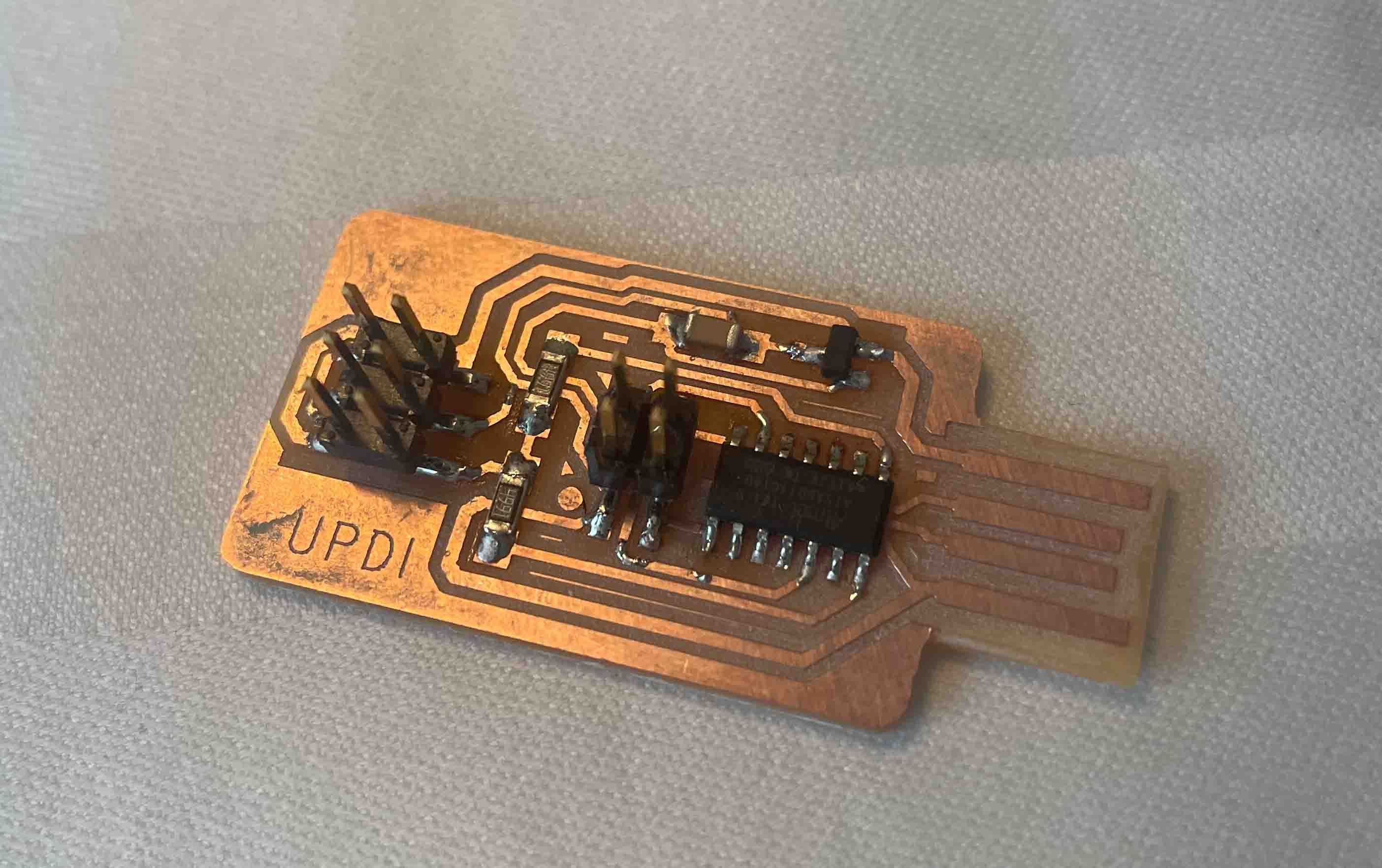
For my PCB production, I used Rolands SRM-20 Desktop Milling Machine, which has the ability to mill a broad range of materials ranging from wax, foam, acrylic to the FR-1 material used for my own PCB production. In addition, I used both CopperCam software (to transform my Gerber files), and Rolands VPanel controller via the workstation iMac.
The FR-1 sheets used consist of a very thin layer of copper (can be double sided) over a non-conductive phenolic resin material, which is a very cost effective option, is flame retardant, and a much safer option, especially compared to options such as FR-4, which is a glass fiber epoxy laminate.
Accessing PCB Design
Although my plan was to access these files via the workstation iMac, I also downloaded the 3 files onto a USB.
CopperCam & Preparing Design
Add discription of CopperCam
- Open up the “Programmer-SWD-D11C-F_Cu.gbr” file on CopperCam; File > Open > New circuit
- File > Dimensions > Then make sure the margin setting is set at 2mm
- File > Origin > Set both Y & X positions at 0mm
- Parameters > Selected tools > Engraving Tool select the .2mm-.5mm Engraving Tool, Cutting Tool select the Cutting Tool .1mm diameter. Ignore Hatching Tool, only the tow mentioned tools should be showing on the Selected tools section on the right. Press OK
- Via the button that looks like a sideways green lollipop, Set number of successive contours at 4. Options to also adjust the circuit pathway thickness is available under this option, to start with I did not adjust design.
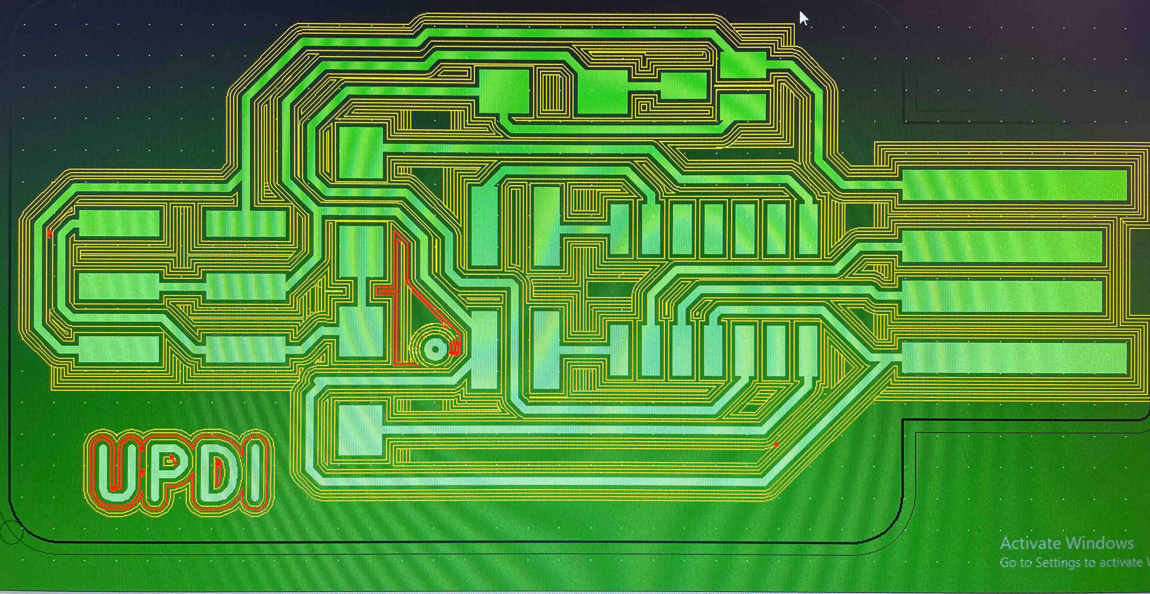
- A preview shown in red should then be produced, this preview can be turned on/off via the red circuit board button up top, this option is great when experimenting with pathway thickness etc.
- Select the button with lighting / drill bit, under Output, Section 1 should show Engraving, Section 2 should now show Cutting. Under XY-zero point select White cross, under Z-zero point select Circuit surface. Save the two files, ideally listing tool sizing (good practice) in file name, after the files are saved, software lists one of t2 & t3 in file name; t2 = engraving, t3 = cutting.
Note – CopperCam is a free software to download, a great way to learn the software at home before heading into the lab Click Here
Vpanel & Prepping Machine
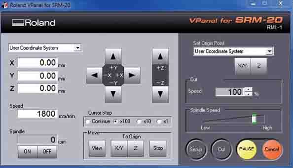
Vpanel is the controller and user interface for the Roland SRM-20 machine, with much of the preparation to mill co-ordinated via this panel on the iMac.
A key point to remember is the engraving and cutting tool bits are very delicate and easily broken, so each stage, especially when adding / removing the tools or setting z origin, should be conducted with great care.
- Press View button on VPanel, the platform within the machine should be presented forward, left cover and place FR-1 board onto platform, using double sided tape to stick in place.
- Use X / Y directional keys to move Drill Chuck inline with desired X / Y origin
- Life the Headstock / Drill Chuck to top position using the +z directional button
- Select the 0.2mm-0.5mm engraving tool, loosen Drill Chuck with hex key (counter clockwise), place engraving tool all the way in until orange plastic is sitting against Drill chuck, tighten (clockwise)
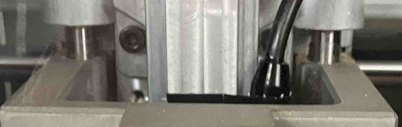
- Using z directional arrows, lower tool bit until circa 1cm (as shown above) of the duel rods are showing, while always making sure the tool bit is clear of hitting the FR-1 board. You can also adjust “Cursor step” to setting x100 or x10 for smaller incremental movements.
- While making sure you secure the tool bit at all times, using hex key release the tool and lower it very slowly, until its sitting about the width of a piece of paper off the FR-1 board, then retighten with hex key.
- With great care not to hit any directional arrows on VPanel, under “Set Origin Point”, set both X/Y & Z origins.