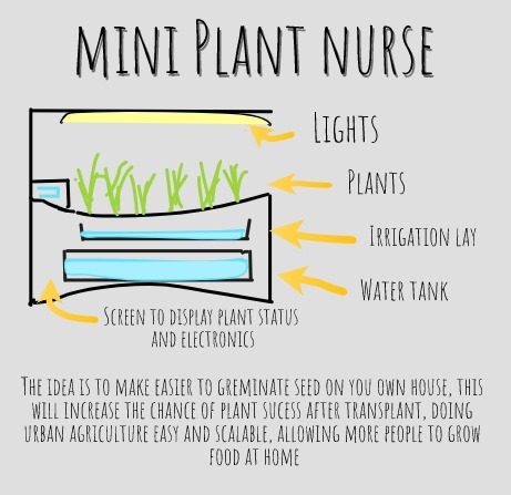
The project should make easier grow your own food. During the covid-19 lockdown I started a small project to grow some organic food with my family. We try to germinate seeds, but the success rate was low, but when we get seedlings they grow easily and allow us to enjoy some lettuce. That help a lot with the motivation to continue the project.
After some research I manage to grow seeds, and successfully transplanted to the grow garden, now having lettuce for almost each lunch salad. I think that creating a device that can help to germinate seed can reduce the time from start to eating your own veggies.
So the idea was to create a mini plant nursery, that can auto water the plants and supply light if needed to get strong plants.It should be easily usable by anyone that want to start growing plants, also used by me to continue growing plants to my garden.
Possible system capabilities
Automate the irrigation via capillarity
Measure light and provide more if needed
Track the water levels and soil moisture
Allow sprouts production
Track grow times and optimal dates to transplant
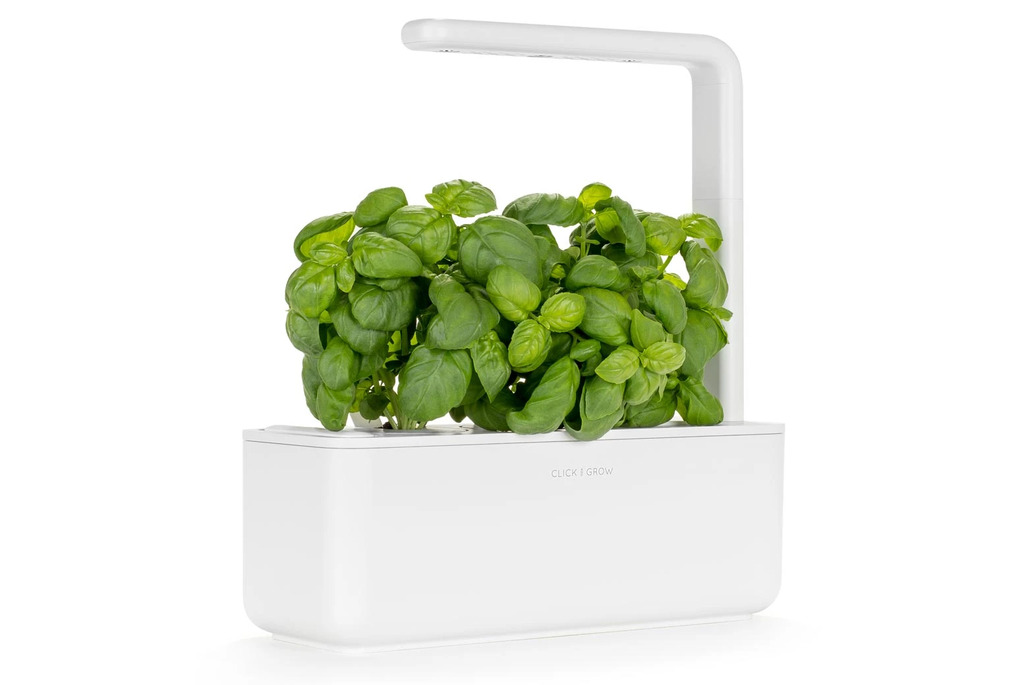
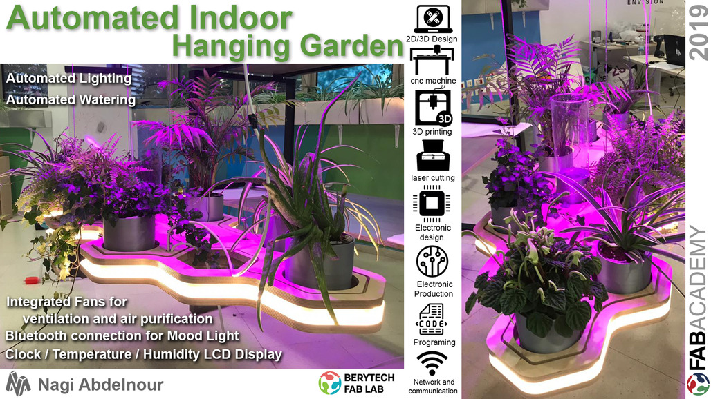
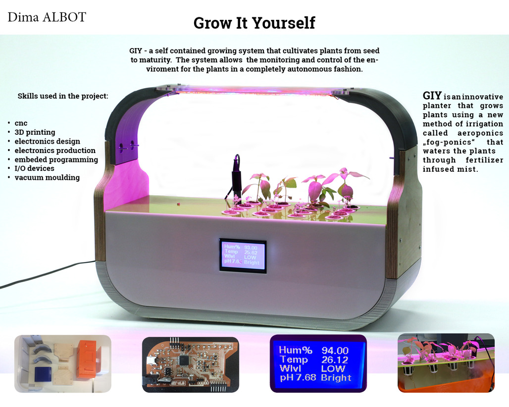
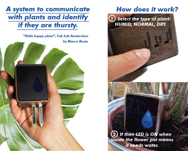
References and ideas
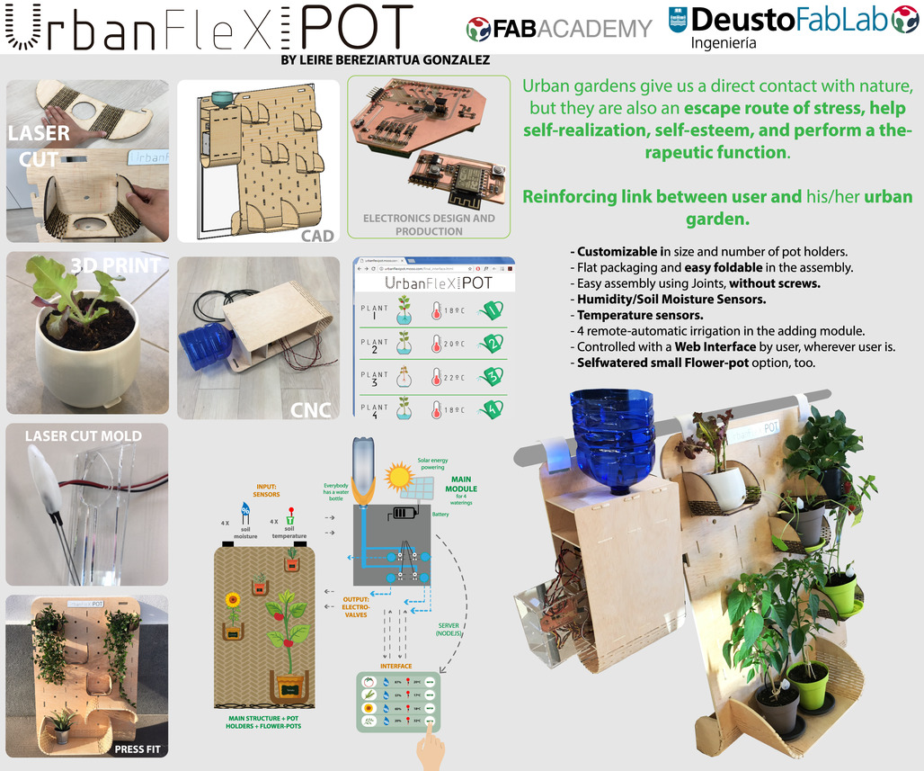
These projects and ideas found on the internet are sources of motivation and ideas for the development of my own project.
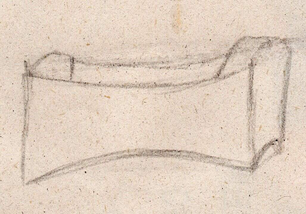
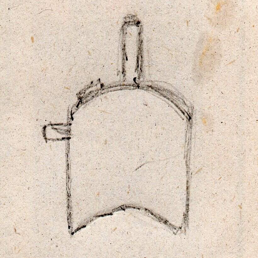
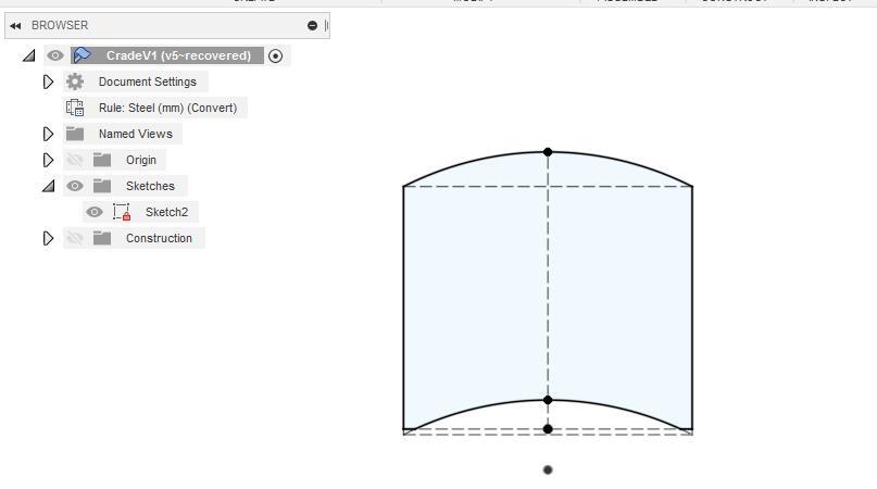
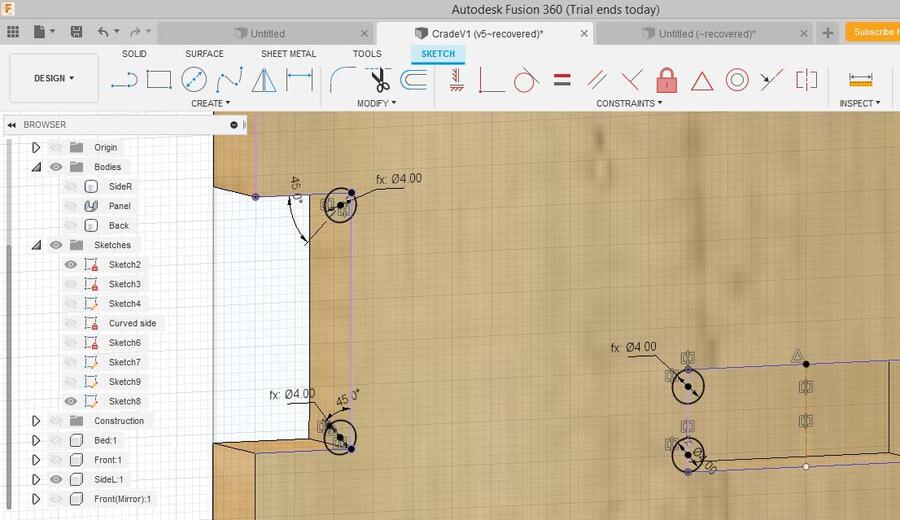
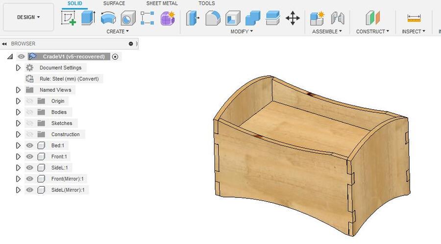
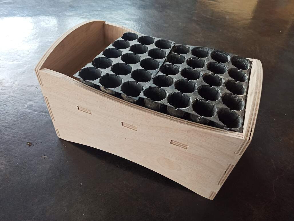
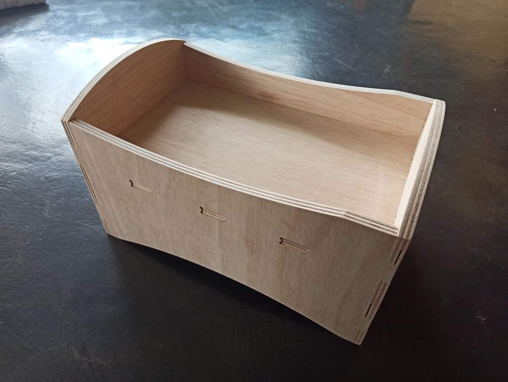
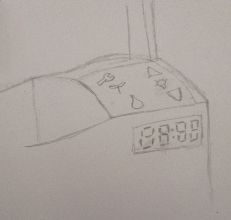
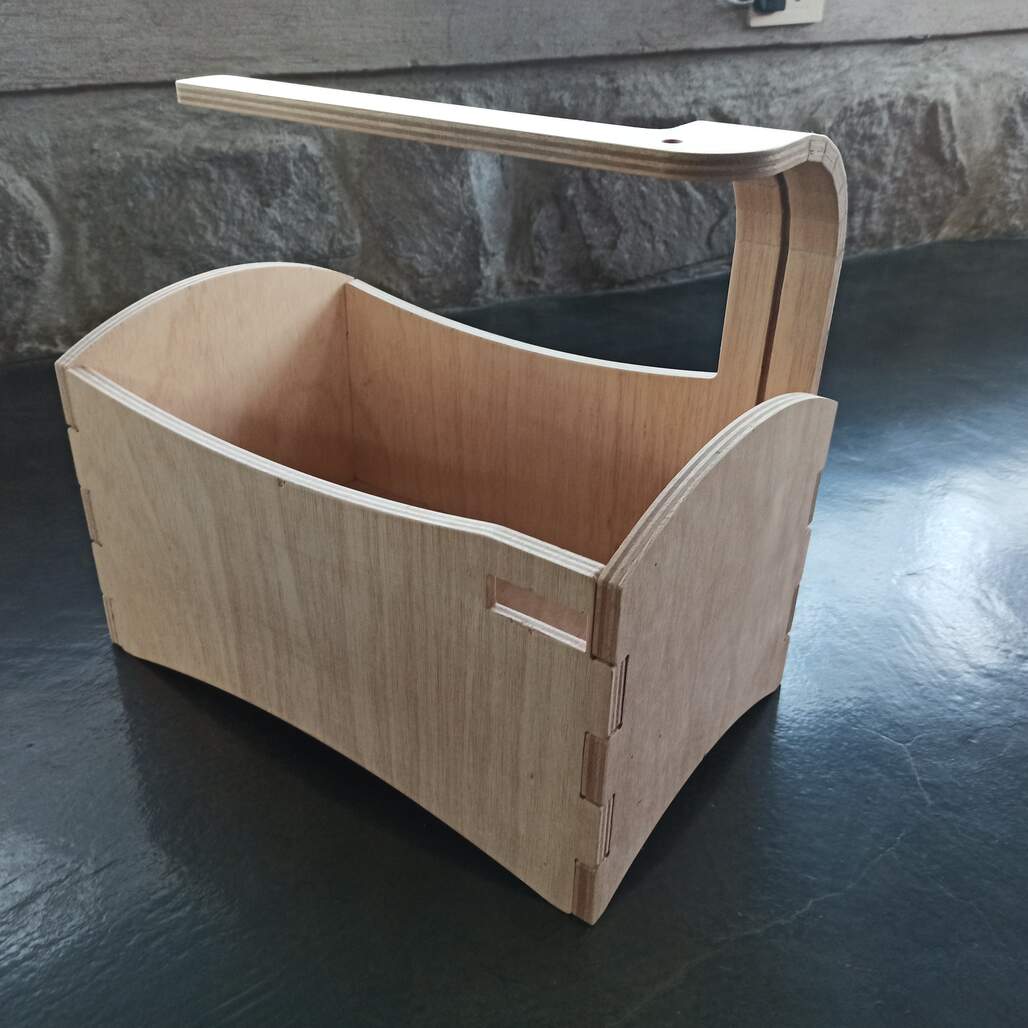
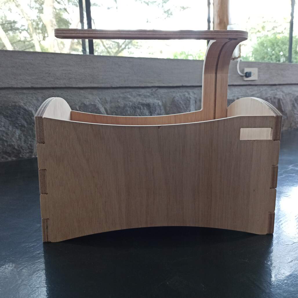
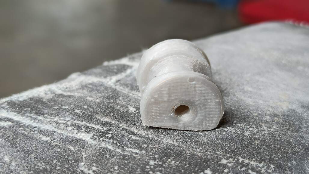
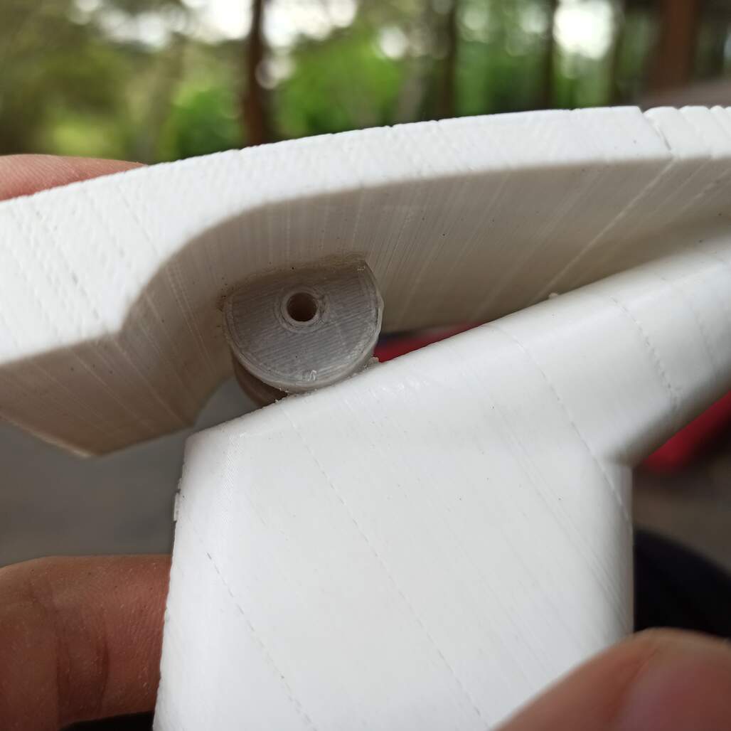
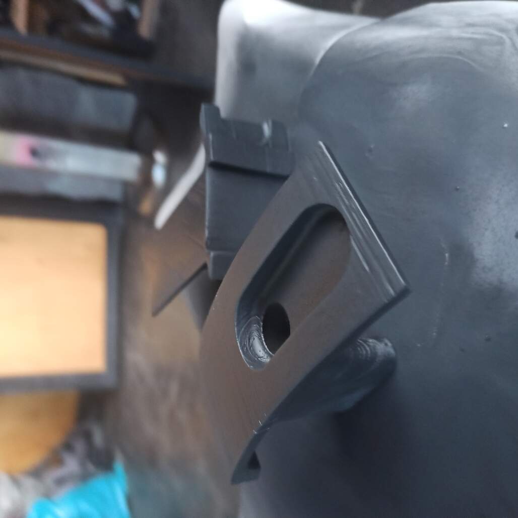
I use this week assignment to design, make and test the size and feel of the possible final shape of my final project, you can see the sketch above transformed into a physical object.
I use the input devices week to explore step response sensors, my original idea was to make the soil moisture sensor, but I did not understand completely the capacitance changes and different methods of measuring it.
So the idea of this week was to experiment with the different methods to measure step response changes.
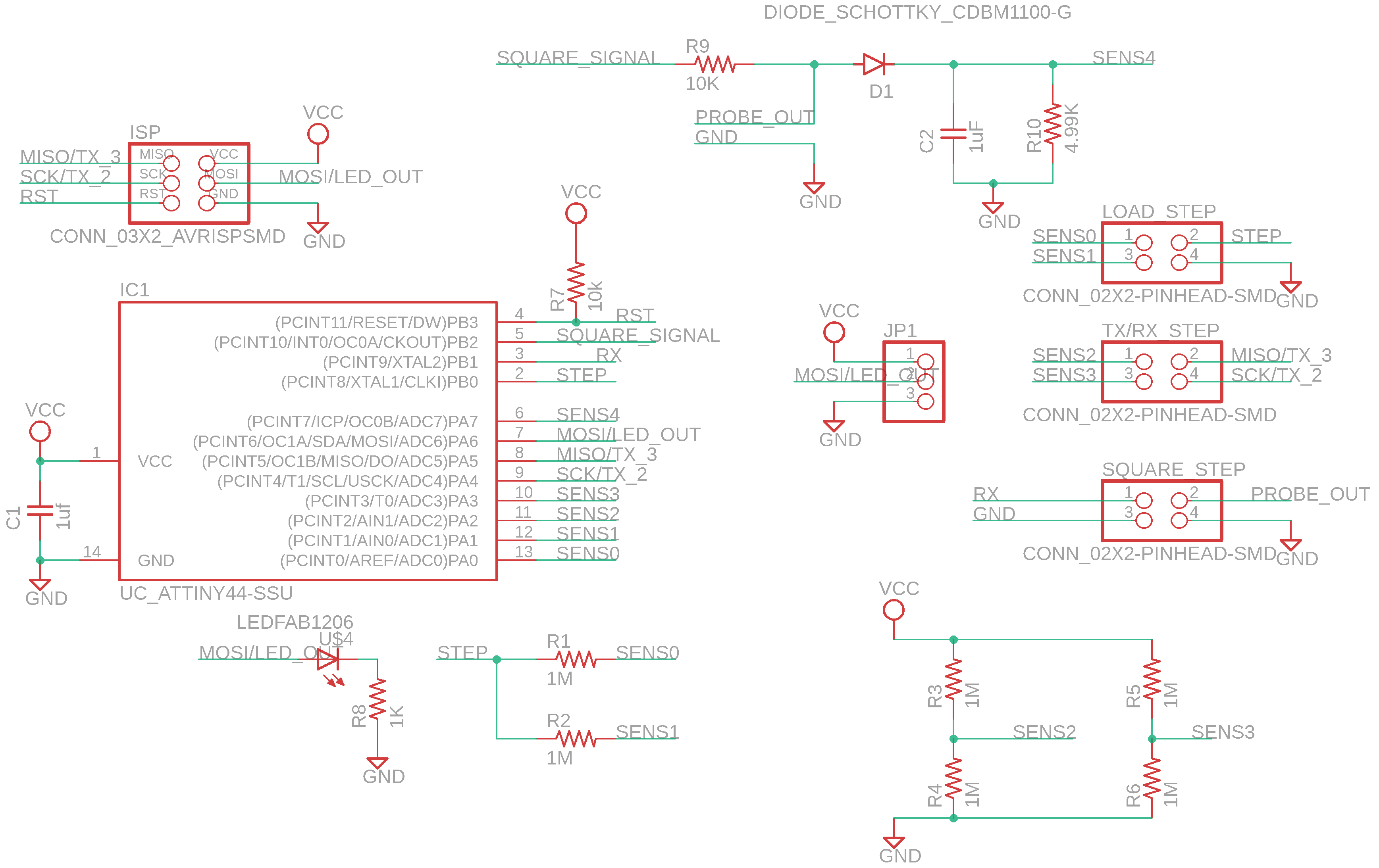
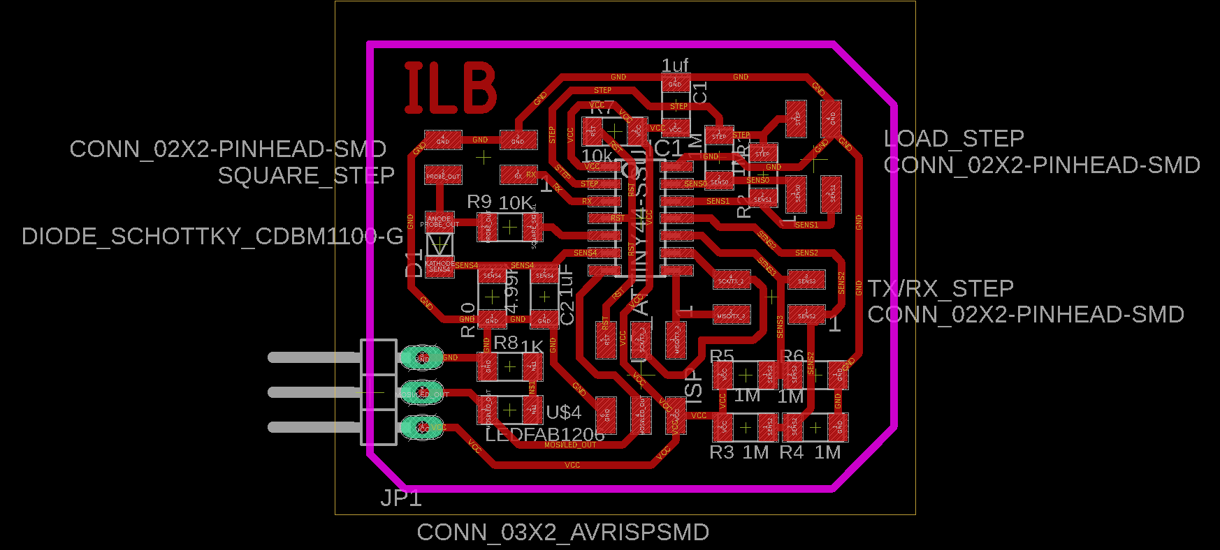
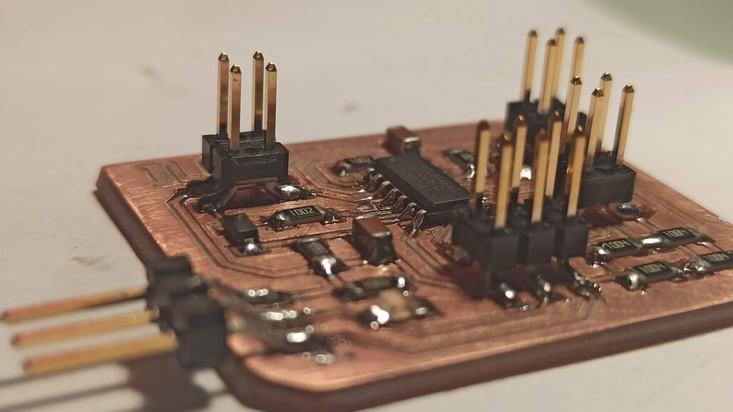
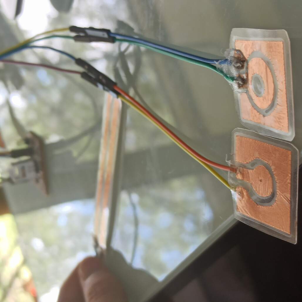
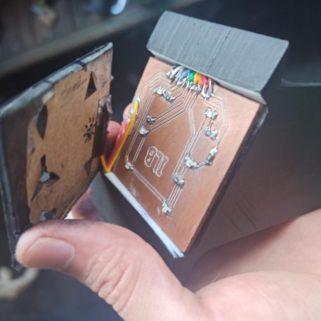
I developed a step sensor board, with TX-RX, Load, and low pass filter as methods to measure capacitance. With this, I grasp a better understanding of how it works and which sensors can be used.
Fabrication of the sensors
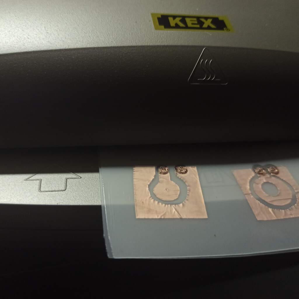
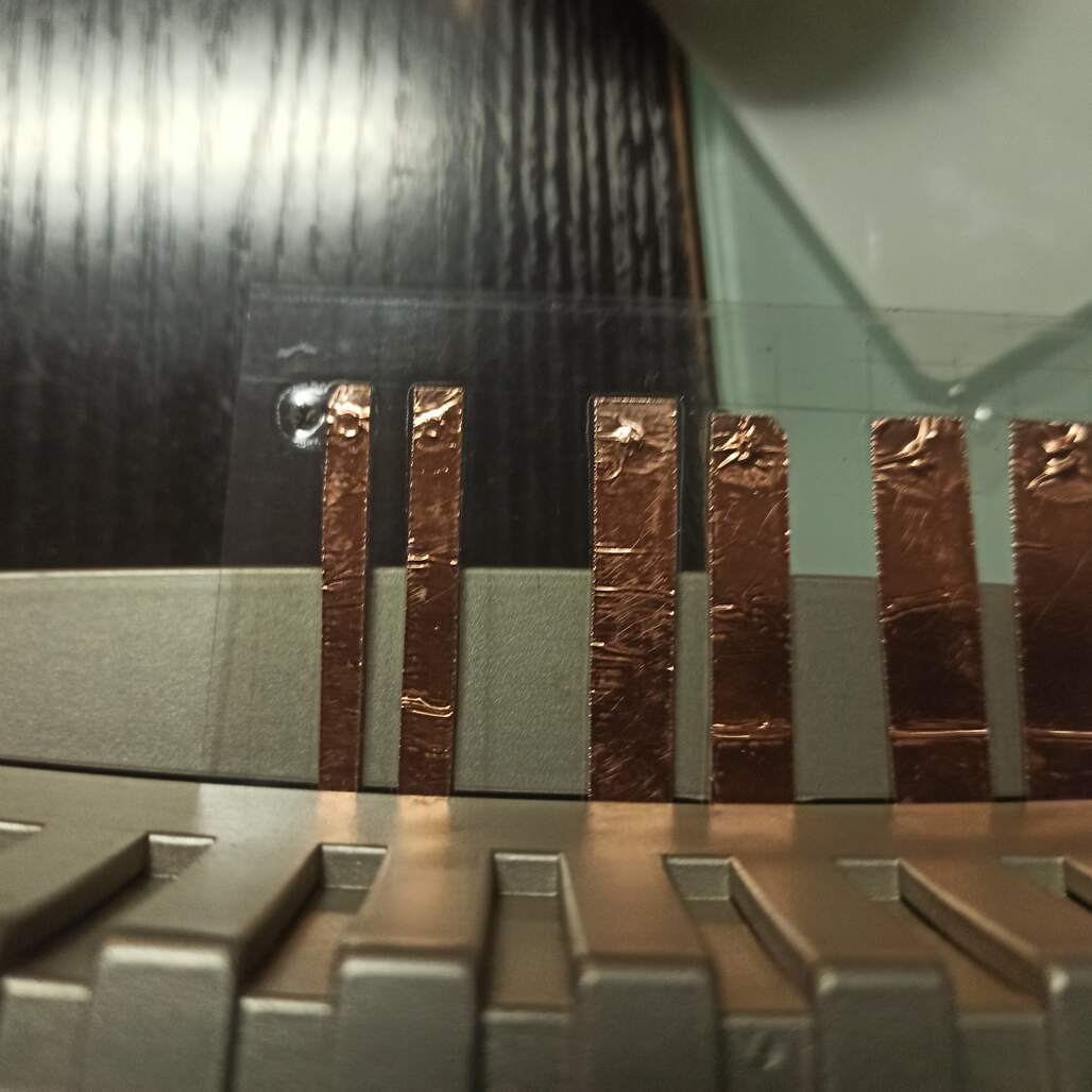
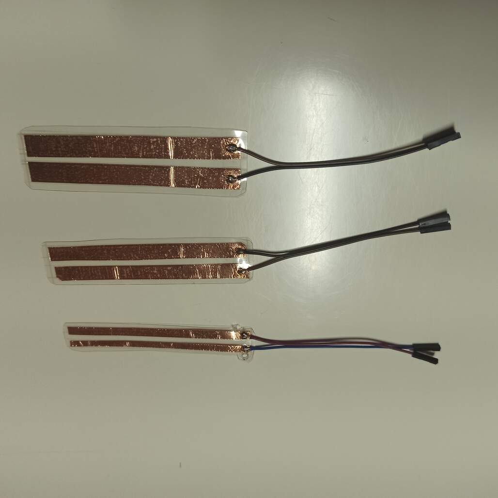
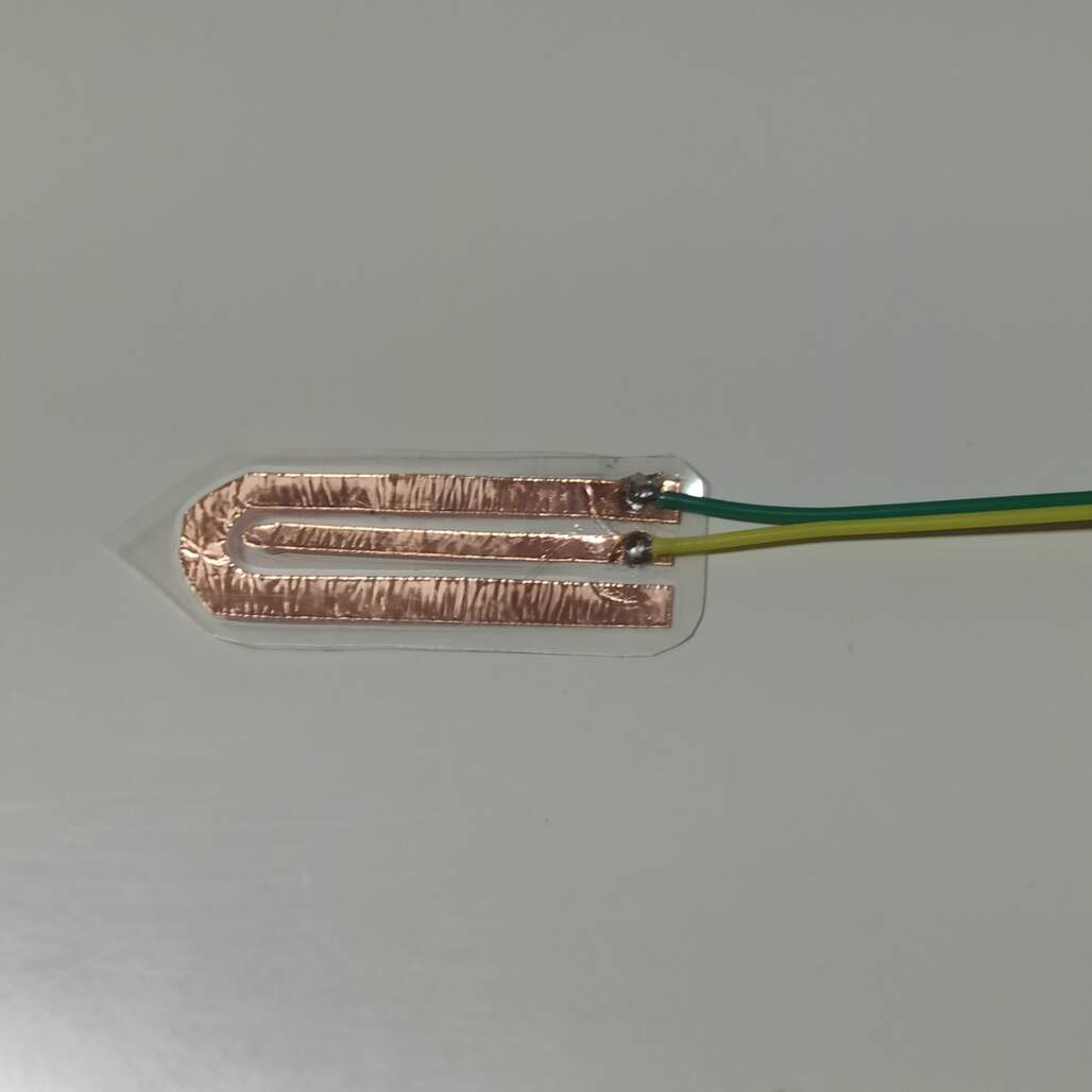
I use some flex copper tape and a lamination machine to wrapped in plastic and make them waterproof. I made them in different sizes to test which will perform better.
This experiment was successful, and I manage to make a Soil moisture sensor, a water level sensor, and some touchpads that I use later on the output devices week.
The idea was to use the output devices week to develop the visual interface of the curdle, it will have 6 icons and 4 seven segment digits for displaying the current time.
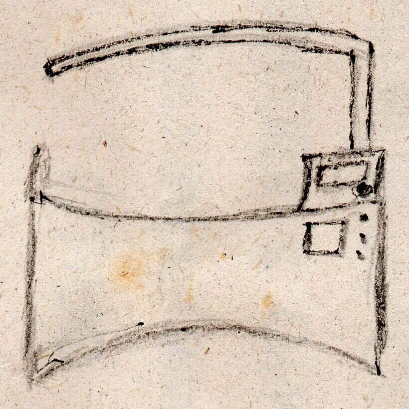
I design two boards that will hold the components for the interface and also the main board of my project, it is split because I want to place it as shown on the sketch below.
Also on my final project, I need to drive led lights and a motor (water pump) as outputs, I add an H-bride and MOSFET on the power module of the mainboard.
Using the interface developed above you will be able to set some basic configurations, but I want to create an advanced settings interface on my phone, that will connect via Bluetooth to my project.
To test I use App Inventor, my goal was to test the connection and how to make the layout of the app, I manage to make an app and discover that is this tool will be enough to make my final application.
Android application that shows the light level sensed by the board that is currently handle light on my test plant curdle
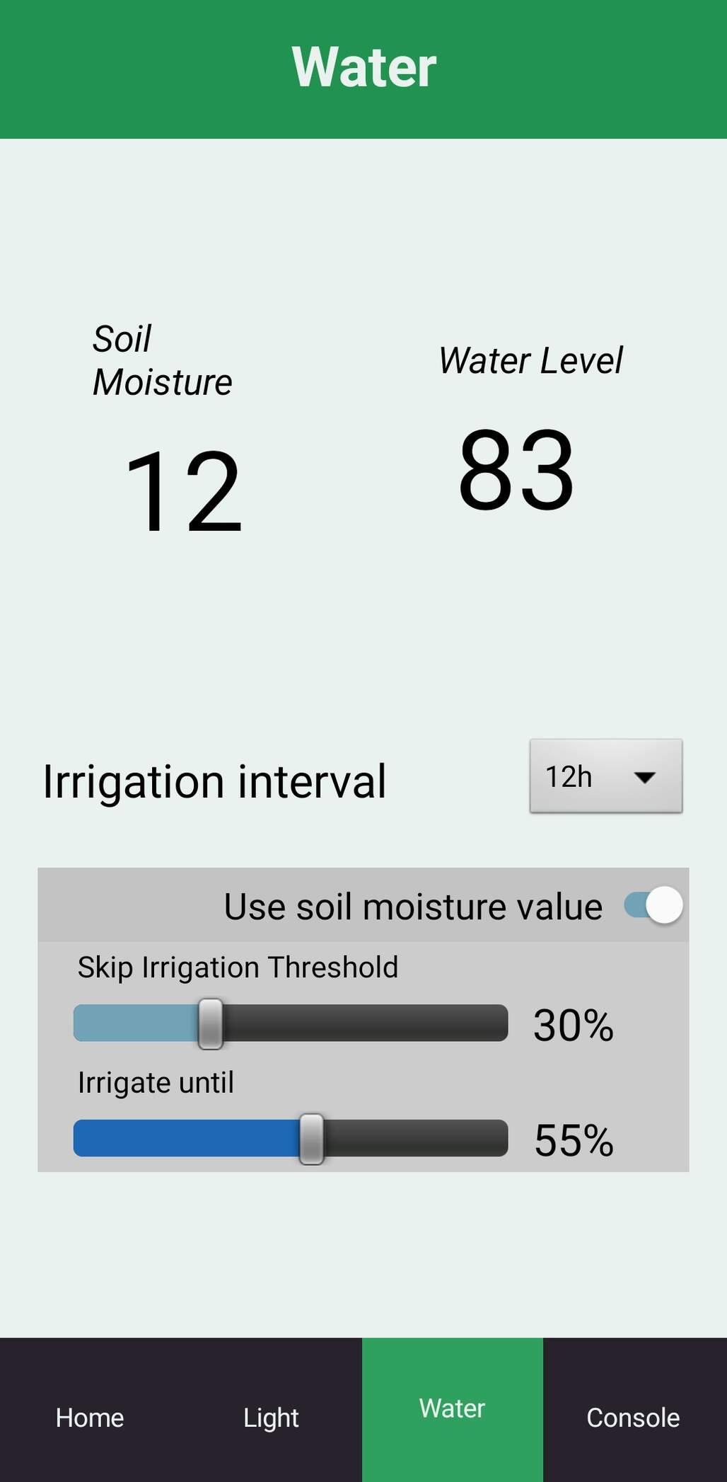
I developed a version 2 of the app, that contains the interface needed to change the settings of the light system and irrigation cycles.
Here is documented my final push before the final project presentation, system integration... activated...
A spiral graph of the features checked the ones solved during the weekly assignments.
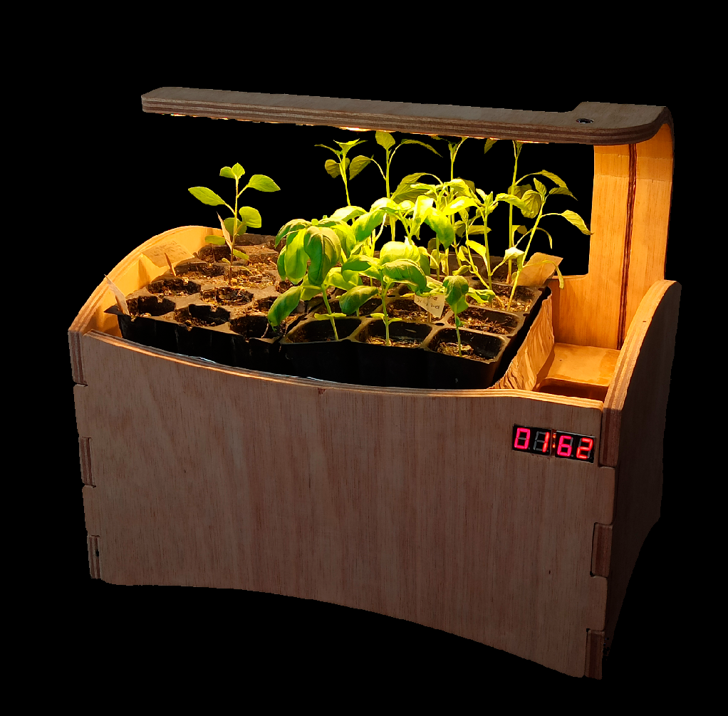
Plant Crib v1.0
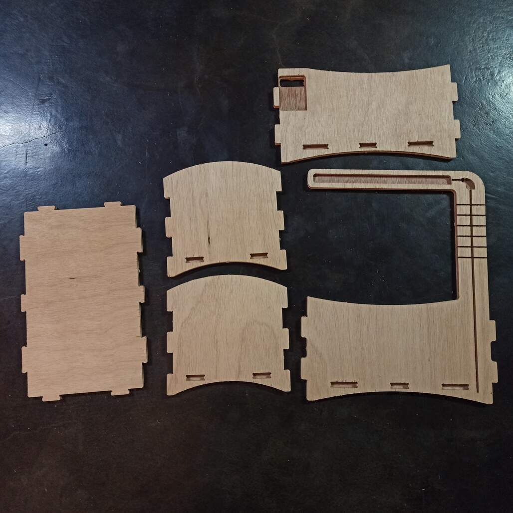
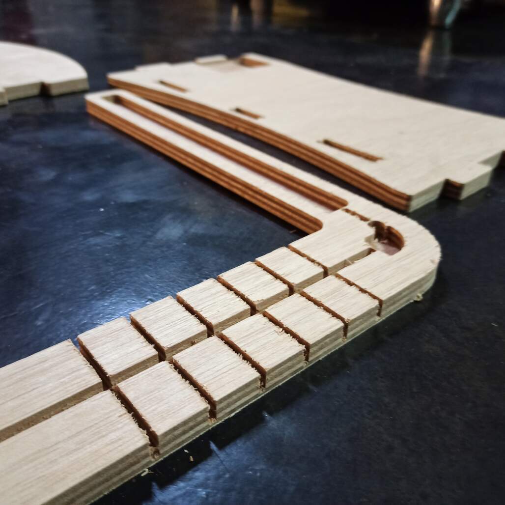
I modify the last version of the crib, adding slots for the mainboard, LED lights, light sensor board, and cables. Also, the base is now deeper to make room for the water tank. The main addition is the light arm that uses kerf bending to make a 90-degree turn and hold the lights.
Design
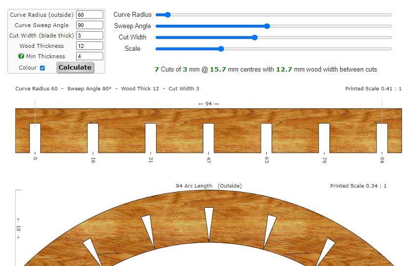
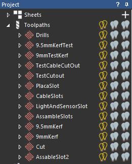
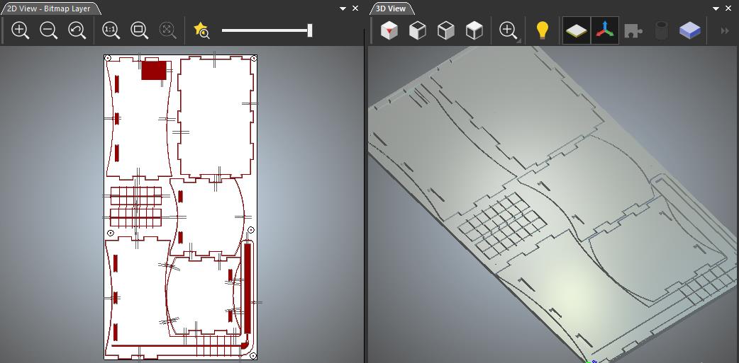
For the kerf bending, I use this useful page it is an online calculator, and use that as a reference to make the slots. Also, I artcam while making the tool-paths I make the assemble slots as pockets to get a clean front face. but I did notice a check box (sharp corners) that will create the toolpath as the selected vector, if unchecked it will round off the outer corners of the toolpath. This created an issue that makes the final finger join more noticeable.
Fabrication
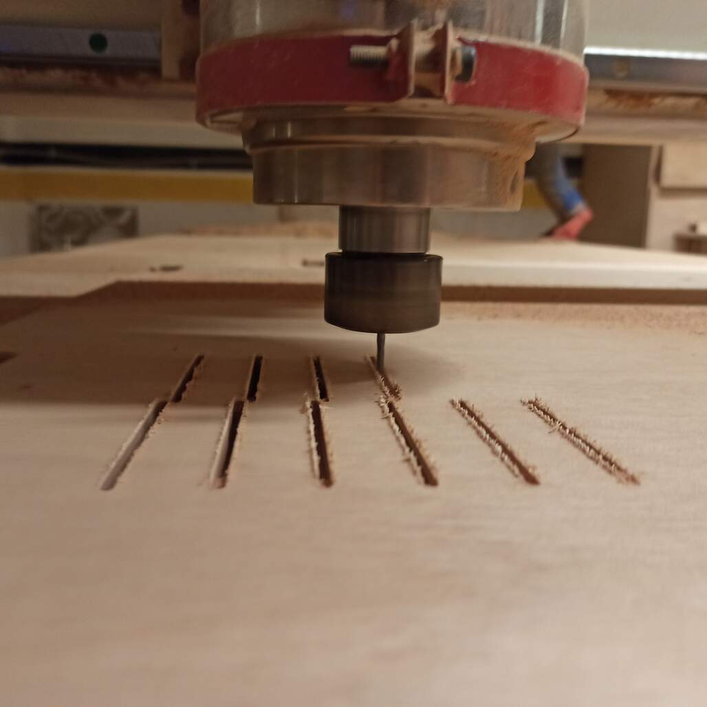
CNC router milling the kerf bending slots, only 6 1/8 inch are needed to bend 90° degrees, would be better to make 12 1/16 inch slots.
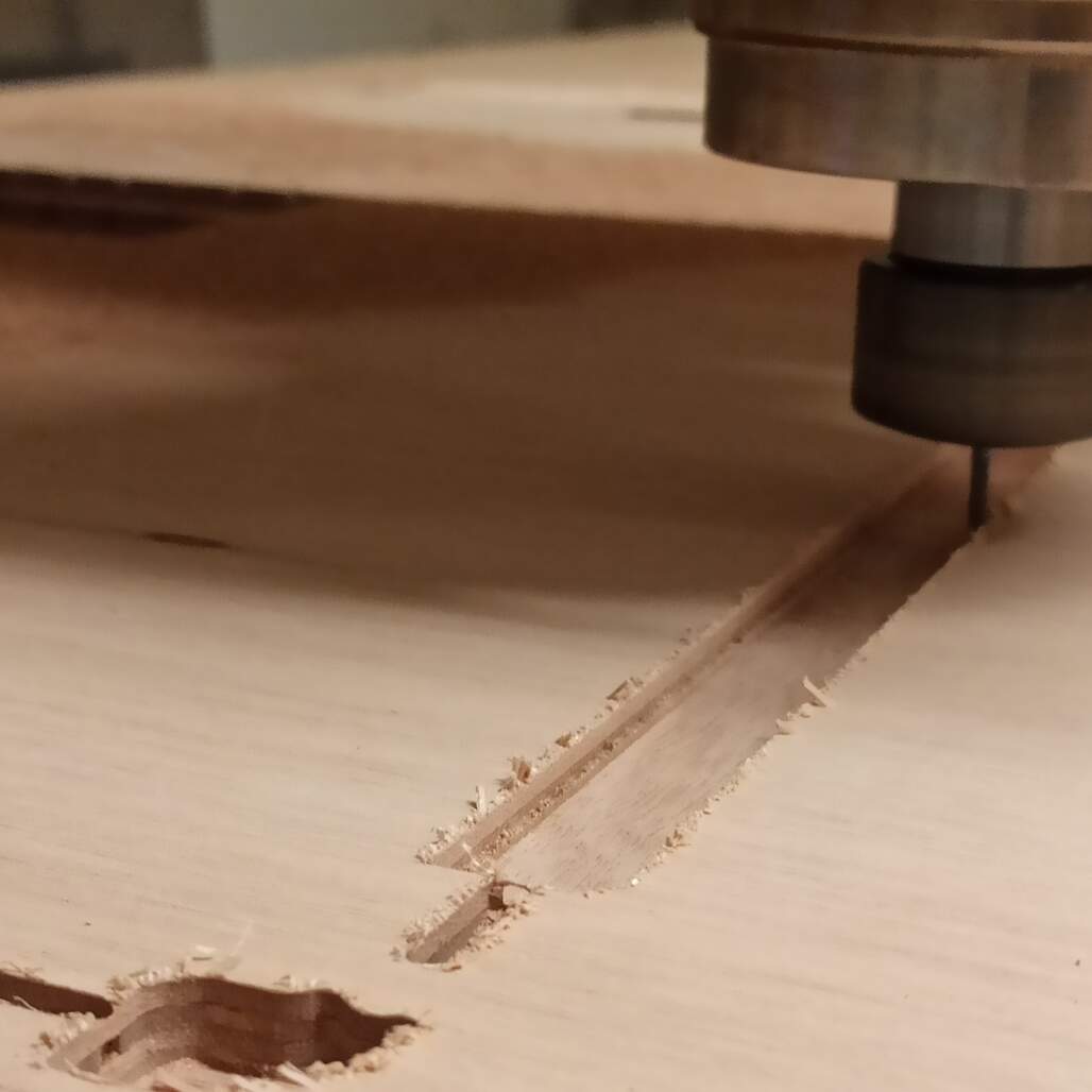
Detail of the machine milling the slot for the LED lights
Results
Final version of the sensors!
Water sensor
I decide to use the same sensors that I made on the Input devices week, I only design and fabricate a new sensor board, that will be connected to the I2C bus.
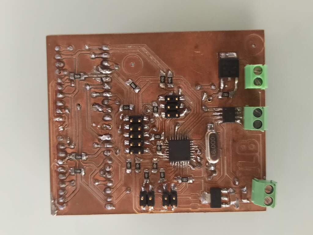
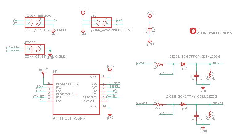
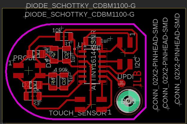
Using Eagle I design this board that will act as a peripheral sensor on the I2C network, it contain two low pass filters that returns the capacitance response to a square wave as voltage measured by the ADC chanel on the AtTiny1614.
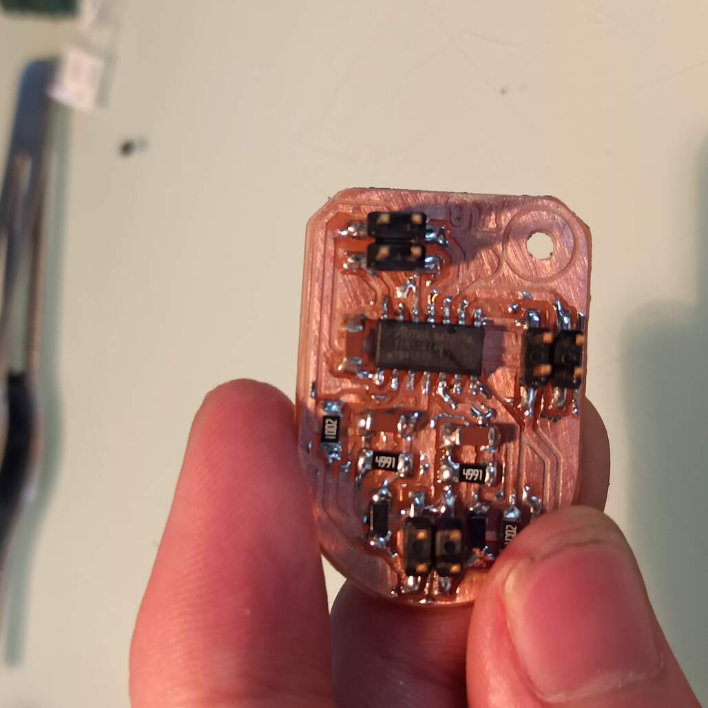
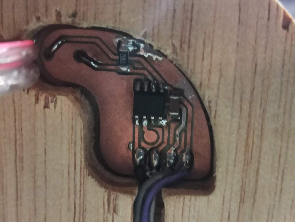
For this board I also redesign the board, I use the EchoIsma made during electronics design week. The idea is to have a tiny board that can me embedded on the light arm and sense the ambient light without the LED light influence.
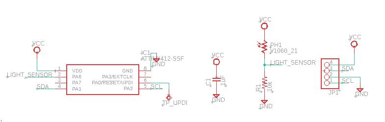
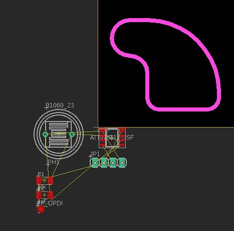
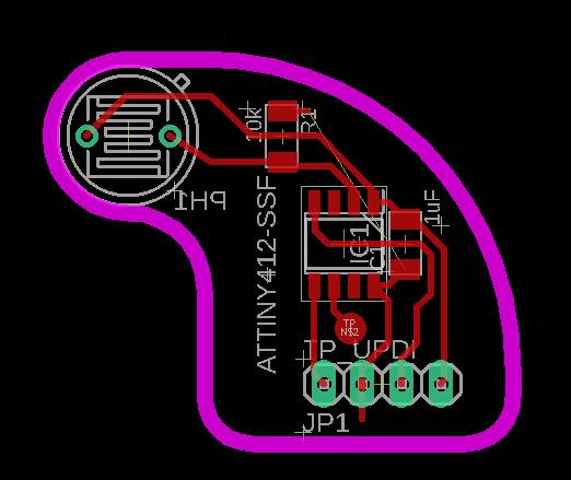
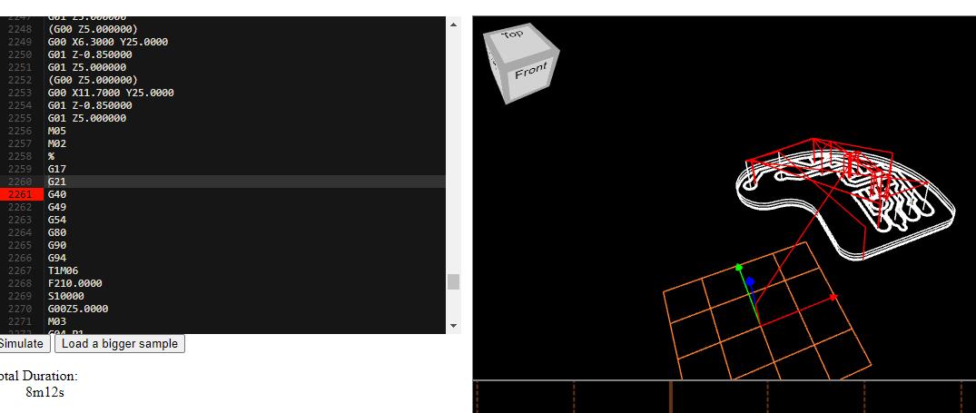
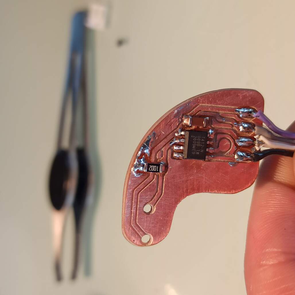
Is a simple board, I use the AtTiny412, because its smaller and has a hardware I2C port. I first draw the outline based on the existing slot, and then place the components and routes. The LDR will be installed on the bottom side, it makes a voltage divider with a 10k resistor. Is then measured by the ACD of the microcontroller.
I then simulate the g code to ensure the right dimensions to facilitate the embedding
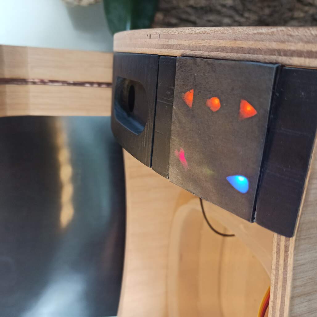
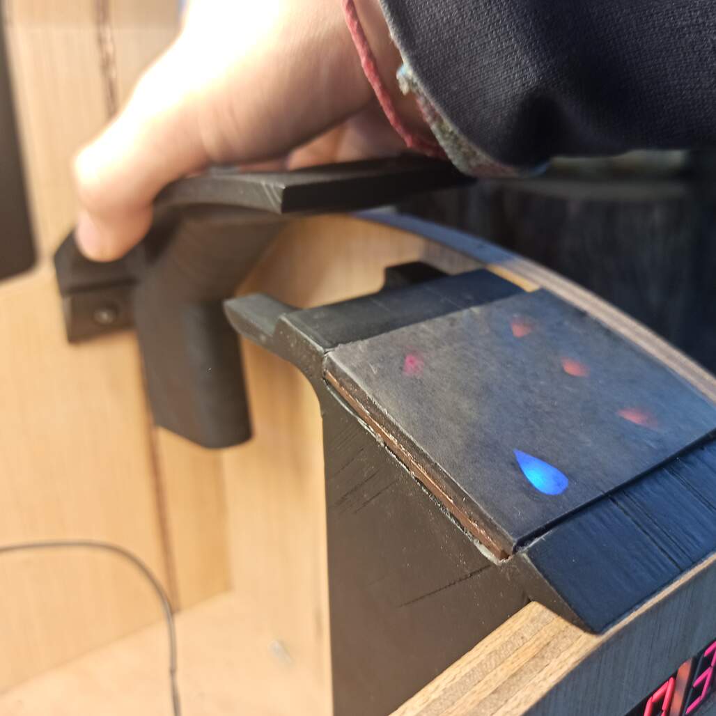
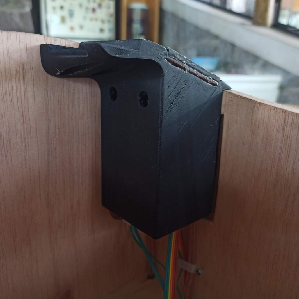
Following the idea developed during the Output Devices week, I needed a way to install the icons and buttons to the curvature of the crib. This panel also contains a way to refill the water tank and I case is needed take out the tray and tank to clean up.
I use Fusion 360 to design the panel, it is divided on two parts one fixed and the other removable. Then I export to .stl and sliced using Cura.
When the parts come out of the printer, the large one was weak, I sand down a 3D printed scrap and glued on place to reenforce the piece.
After some painting, I add a layer of tracing paper printed a gray square to cover the MDF panel and hide the Icons until they are lit from behind, then I glue everything to the 3D printed part.
Using screws everything was mounted on the crib.
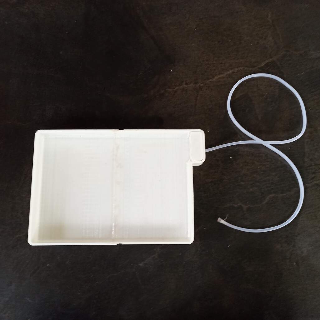
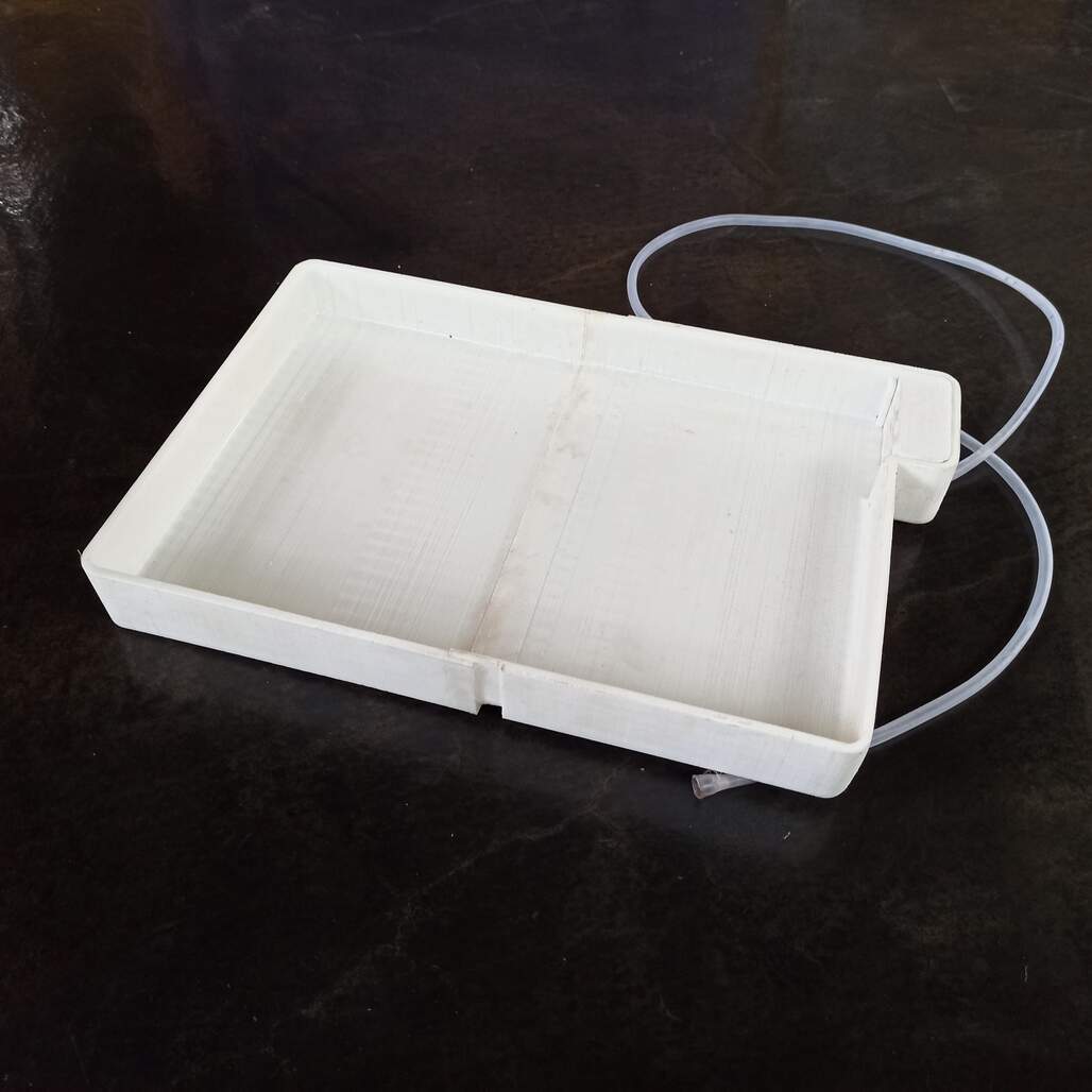
Creating the irrigation tray
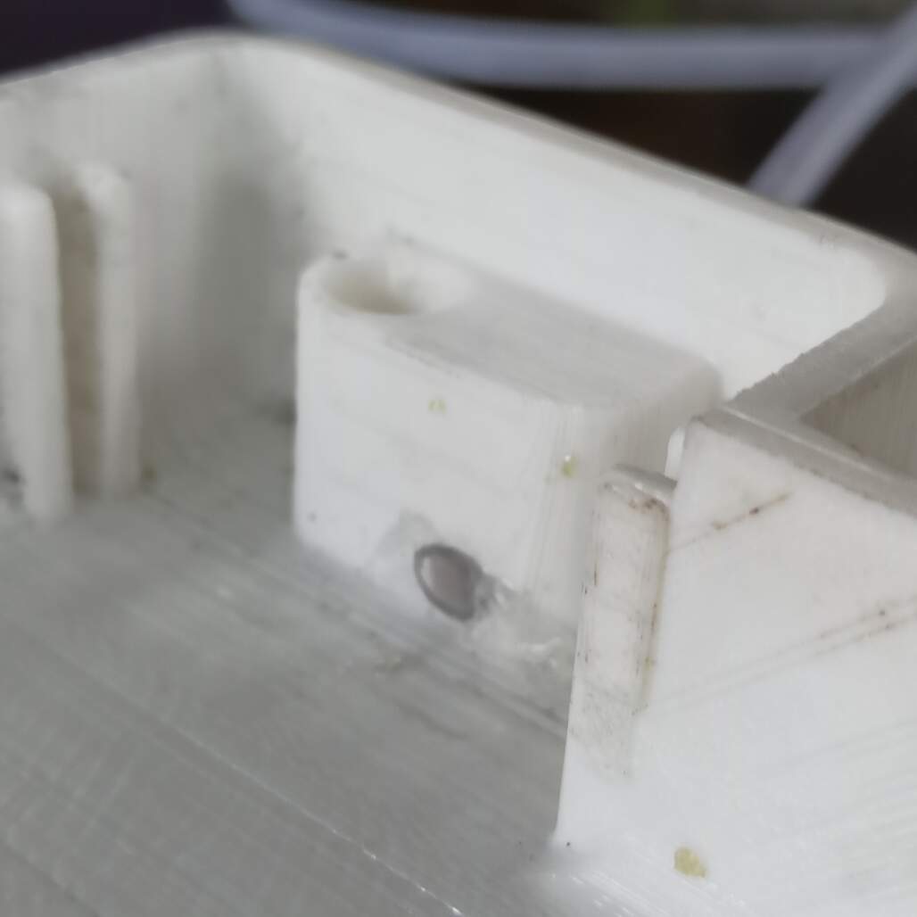
The irrigation system works by floding a tray and letting the plants soil take the water they need, this tray needs to have an overflow pipe and the inlet of the pump.
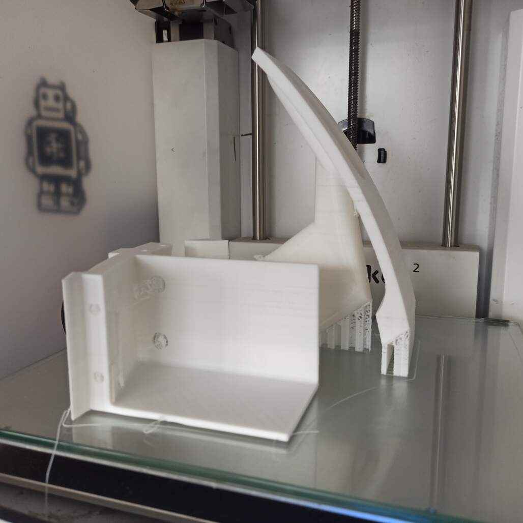
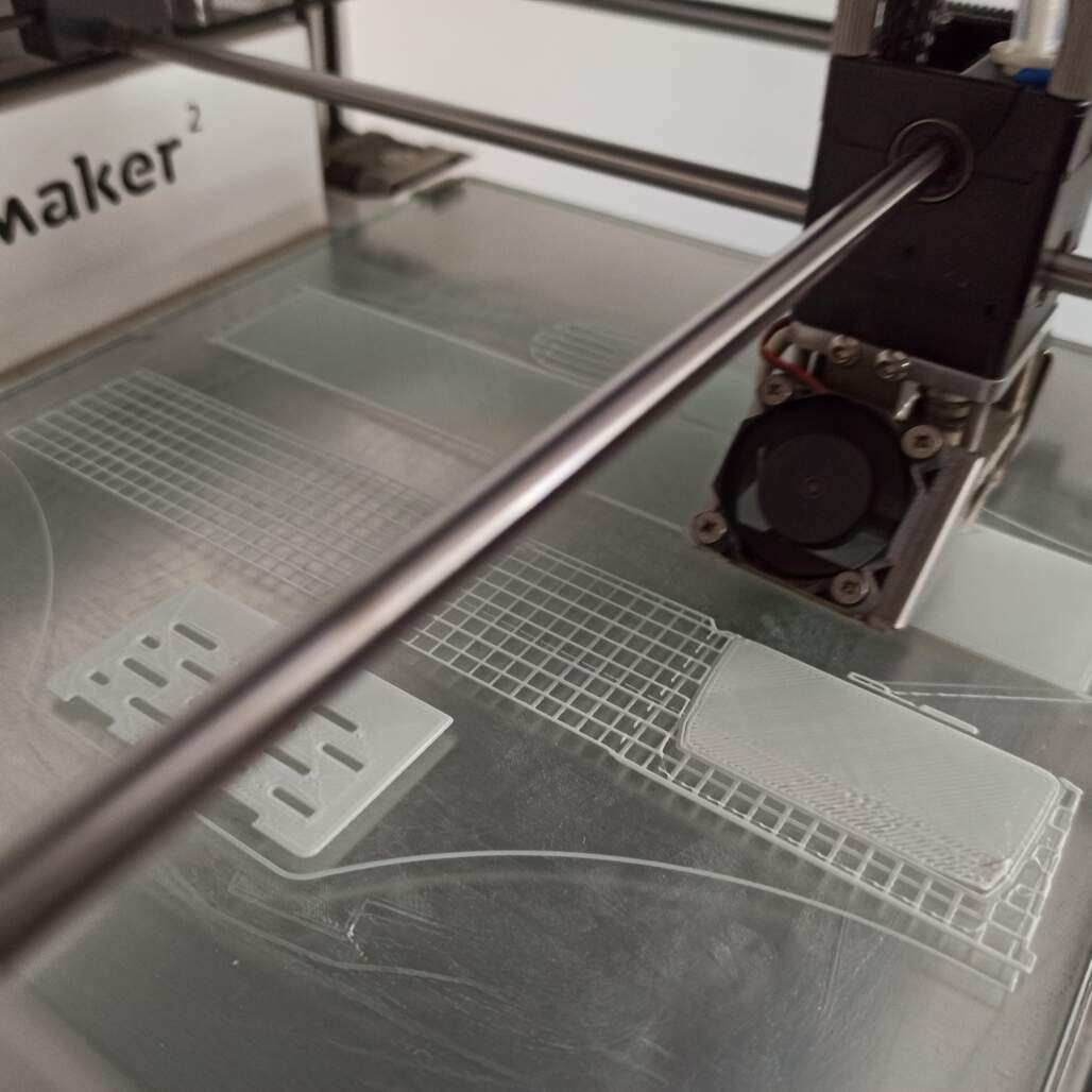
I use Fusion 360 to design the part and split in half, so it can fit inside the printing volume of the Ultimaker 2, then I send the print that take 25 hours to complete.
3D printing process / Overflow and pump pipe inlet detail.
Then I also coated the interior of te tray to create a water tight surface that can hold the water during the irrigation cycle.
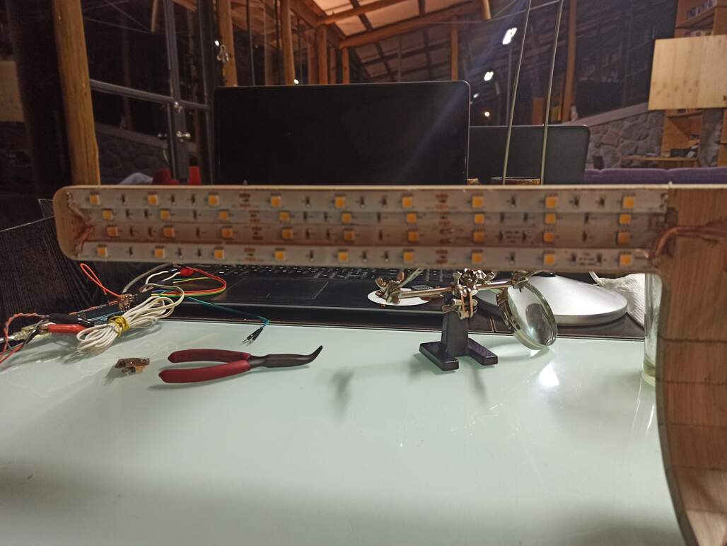
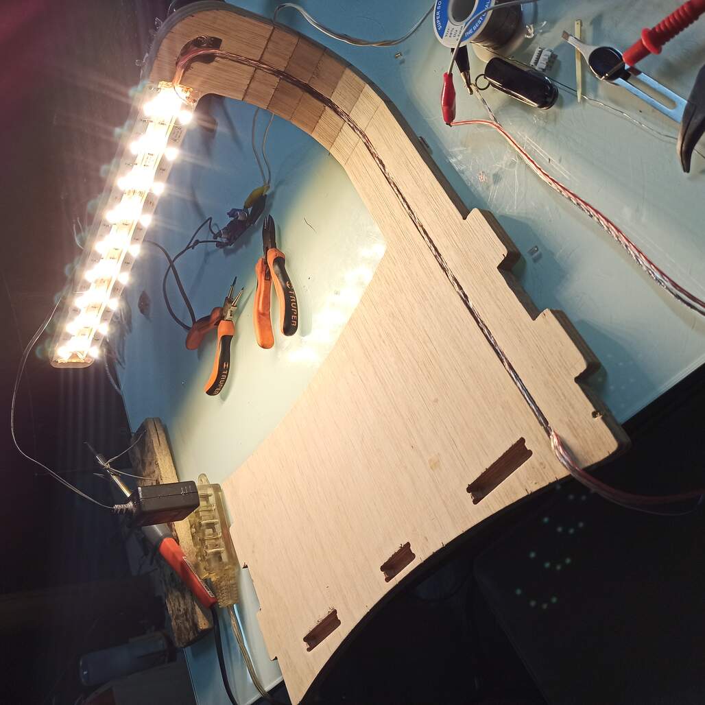
And here comes the light!
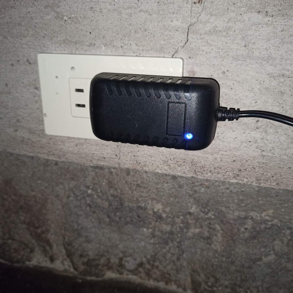
For the lIght source I use some LED strips, because they can fit easily on the place, I bought a kit that comes with a 12 volt power supply that I also use to power my entire project. Initially the slot was made 2cm wide, but only two strips can be places inside, and the light wasn't bright enough, so I added two strips more, with a total of 36 LEDs.
The LEDs are connected in series, they emit a 3000K warm light.
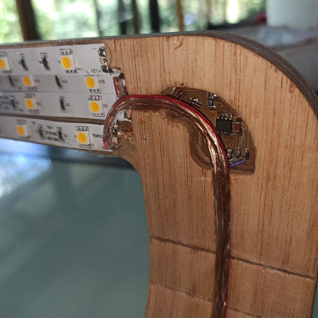
Here you can see the light sensing board embedded onto the light arm, to the left the led strips,
Bluetooth Module
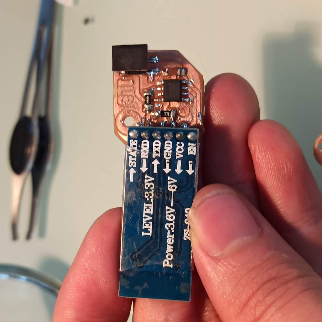
This device will be connected to the I2C bus and it will be on charge of the wireless communication via Bluetooth, using a HC-06 module as antenna.
This is the bluetooth module, sadly the power provided by the AtTiny412 isn't enough to power the module, I have to override it and make the module always active.
Some modification of the schematics is needed to have a transistor that will act as a switch to enable/disable the bluetooth connection. But sadly this will take time, it may be updated after the presentation.
Settings App : developed after presentation
I also created an avdanced settings app, using appInventor, I build on the test app developed during the Application and Interface Programing week, to improve the aspect of it I make a this color palette using Coolors a handy web app.
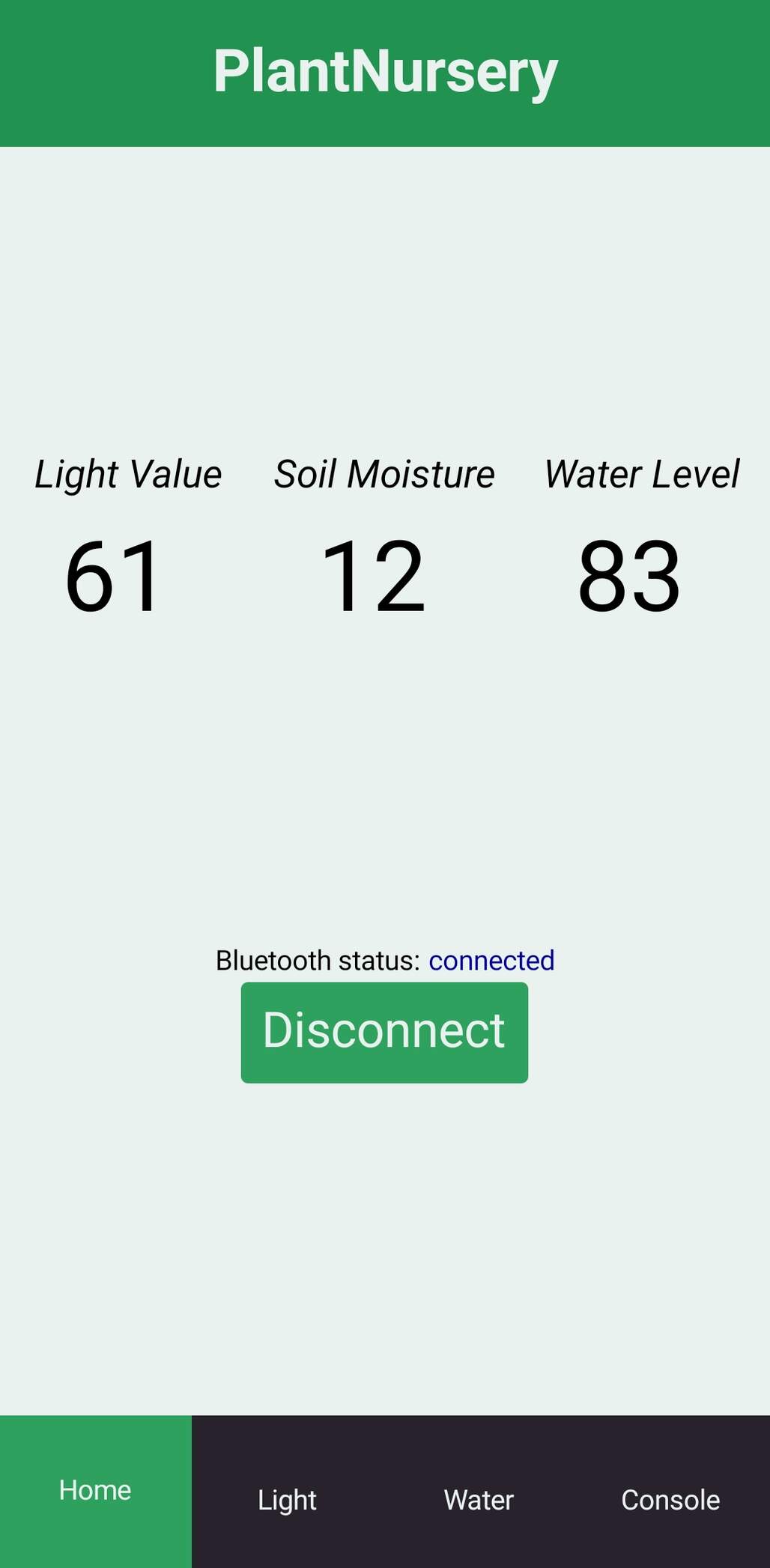
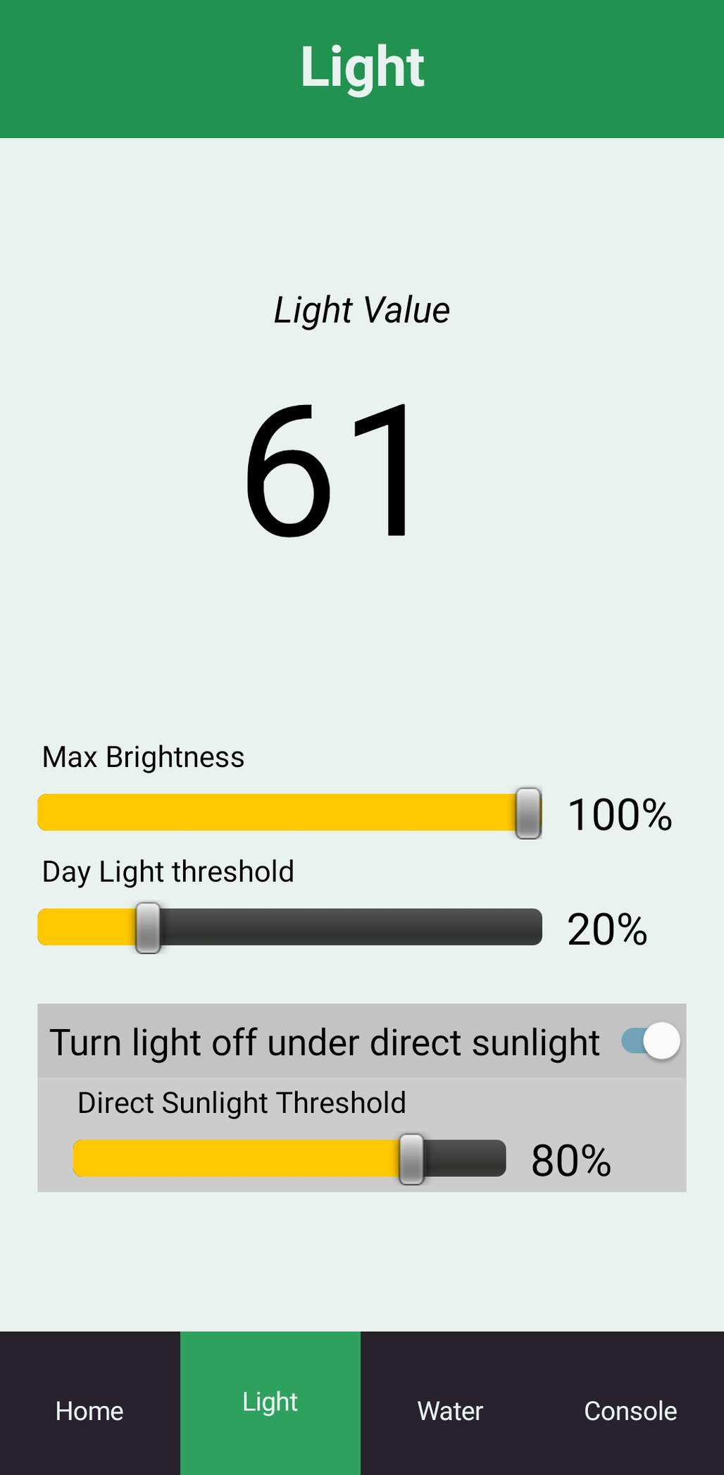
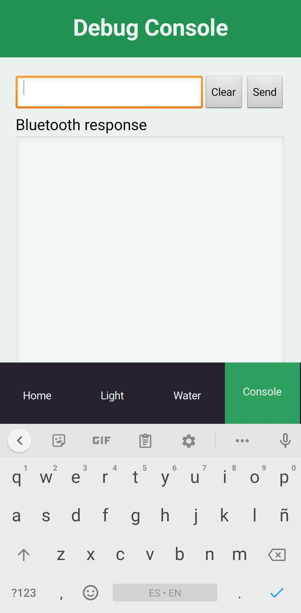
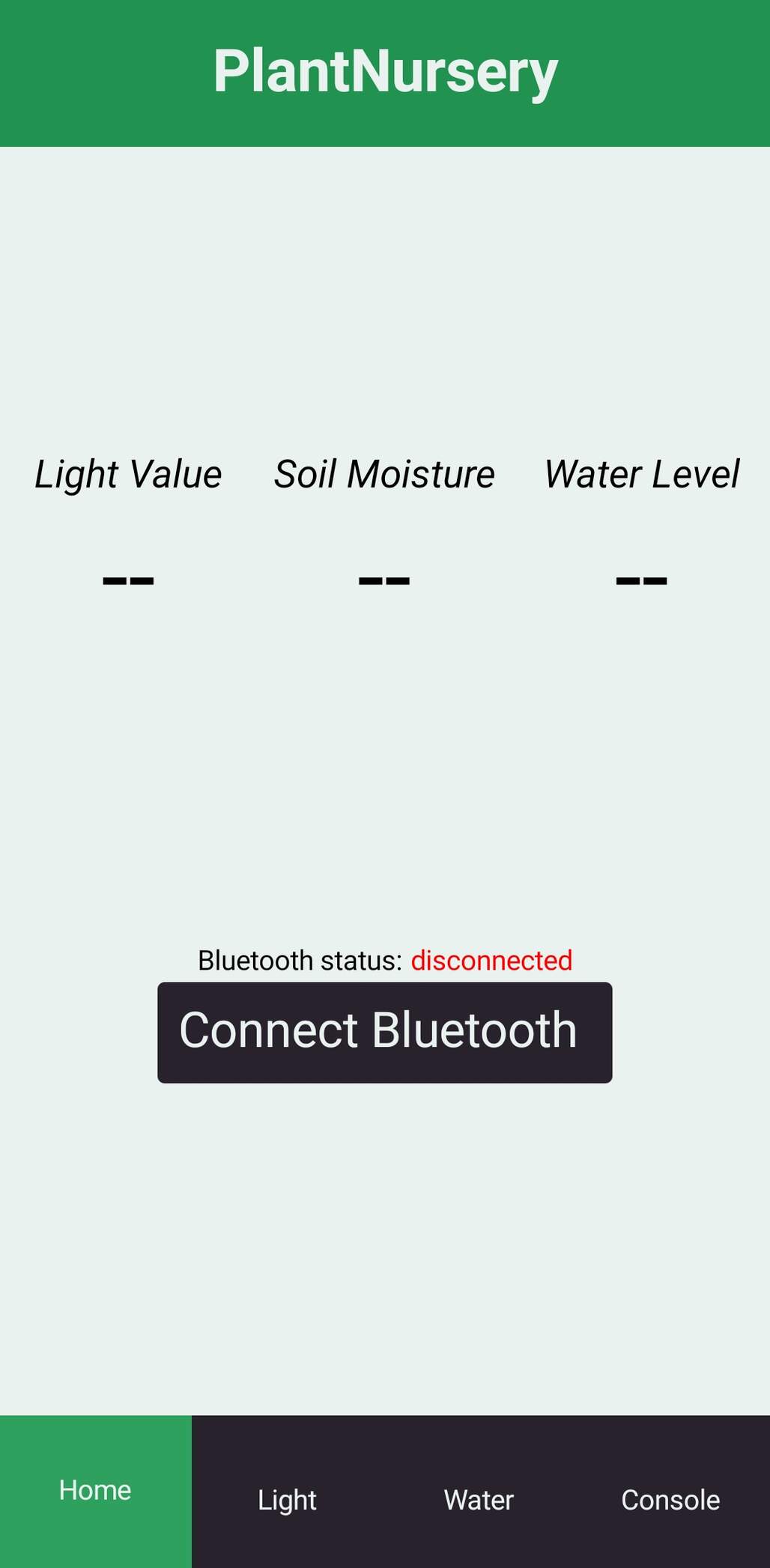
I divided the app on 'tabs', home were you can see the important values and connect via bluetooth, light were you can find all the settings related to the light, water settings related to irrigation, and debug a serial console for testing.
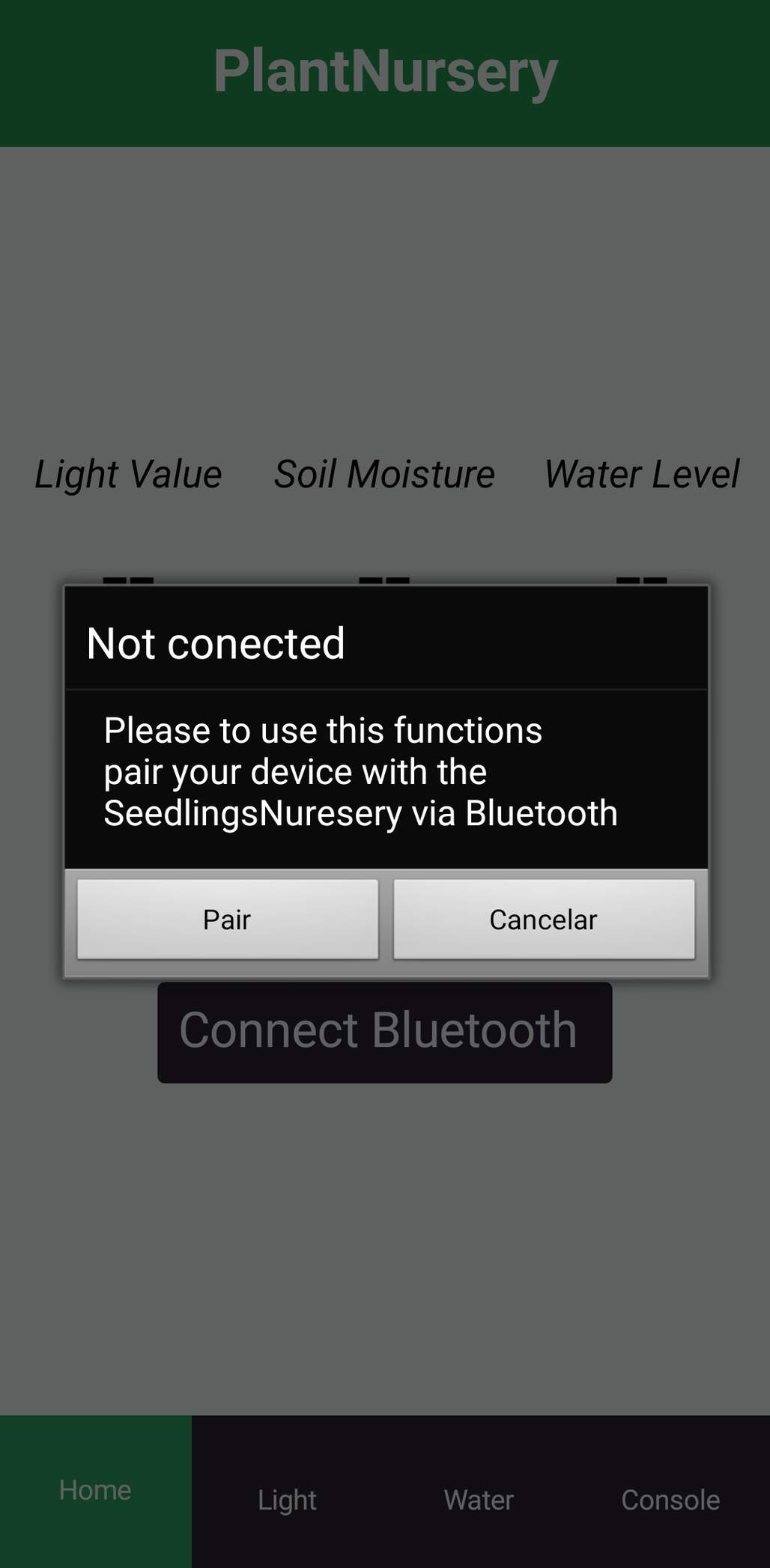
I also added some error messages when not connected via bluetooth, if the device bluetooth isn't enable it open up the settings screen so the user can turn it on and pair with the device. Also the home screen looks different while waiting the connection.
It sends and receive the data using a 'protocol' using chars defined on the settings.h file, used by the bluetooth module to receive and send data.
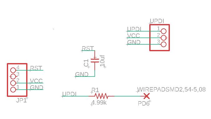
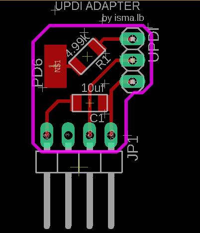
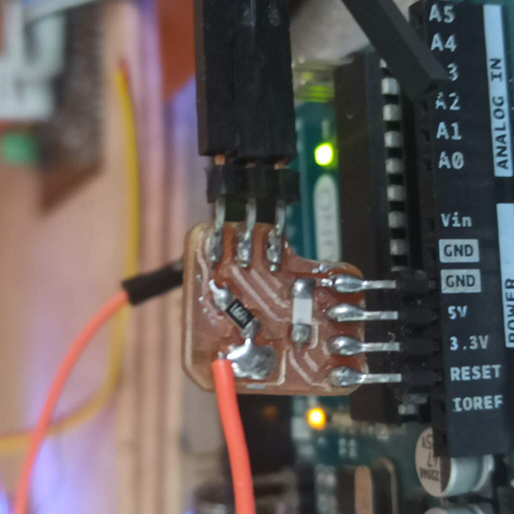
Due to the use of the newest AtTiny I needed a UPDI programmer in order to program the microcontrollers. On the megaTinyCore git page, I found a method to use and Arduino uno as UPDI programmer with some extra components. I design a small board that will help me setup the programing workspace easily.
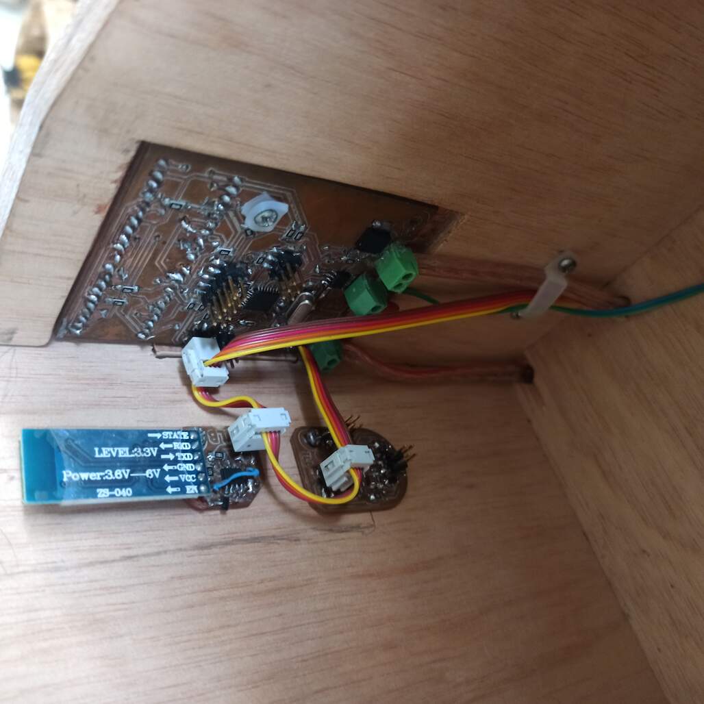
The idea is to integrate the sub systems to create the final assembly. The main thing was to wire all up and connect to the main board, the 12v power supply and the Mosfet driven LED power cable. I also connected a small water pump activated by the H-bridge on the main board.
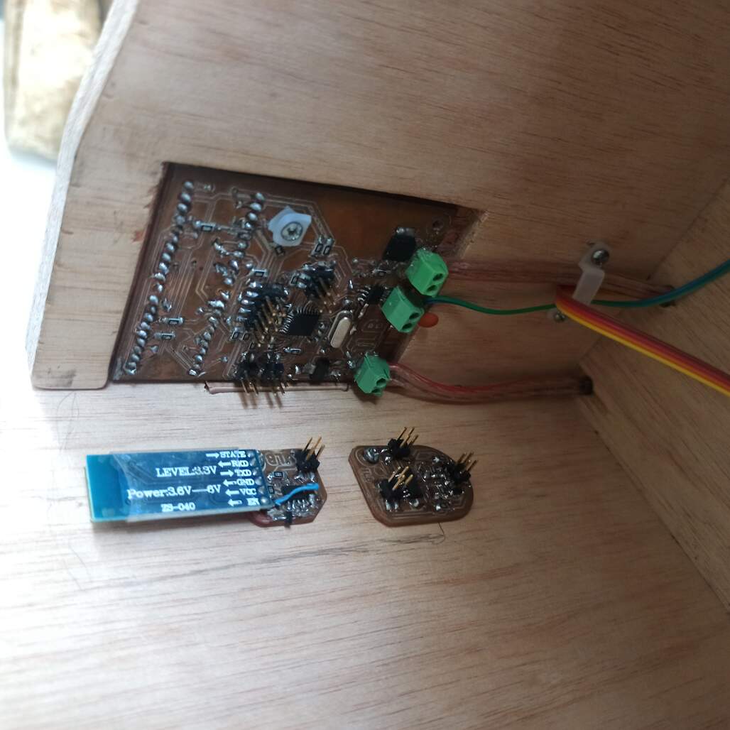
Main board, bluetooth module and water sensing module fixed on place.Boards and modules connected with the power and I2C bus. (4 wire ribbon cable).All cables connected, electronic board cover under the side panel fixed piece
On the main board from left to right the connections of the bottom are the power supply 12v, output 12v to the pump, and output 12v to the LED strips on the top you have a 10 pin header that is connected to the touch buttons and led icons embedded on the side panel.
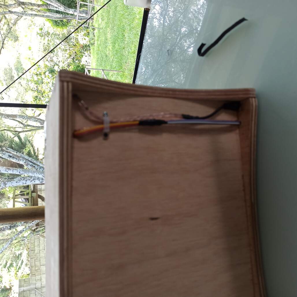
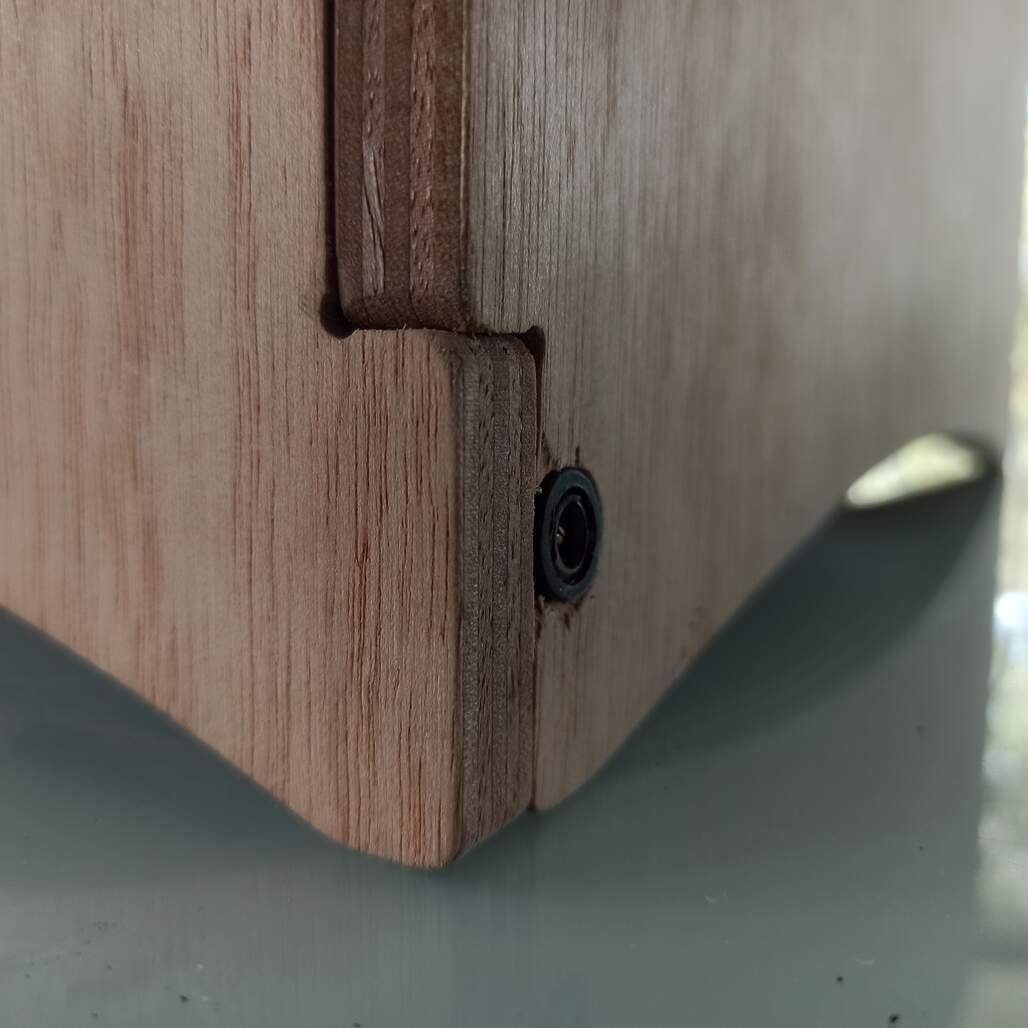
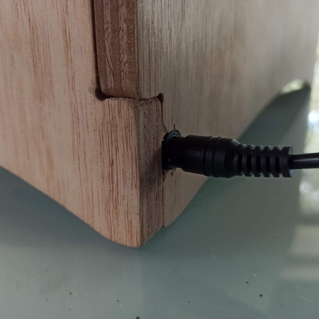
Here you can see how the cables travel on the bottom side to the light arm and power plug located ath be back, as power supply the project uses the power source that came with the LED strip and has the transformer embedded into the plug
Some unfortunate events...
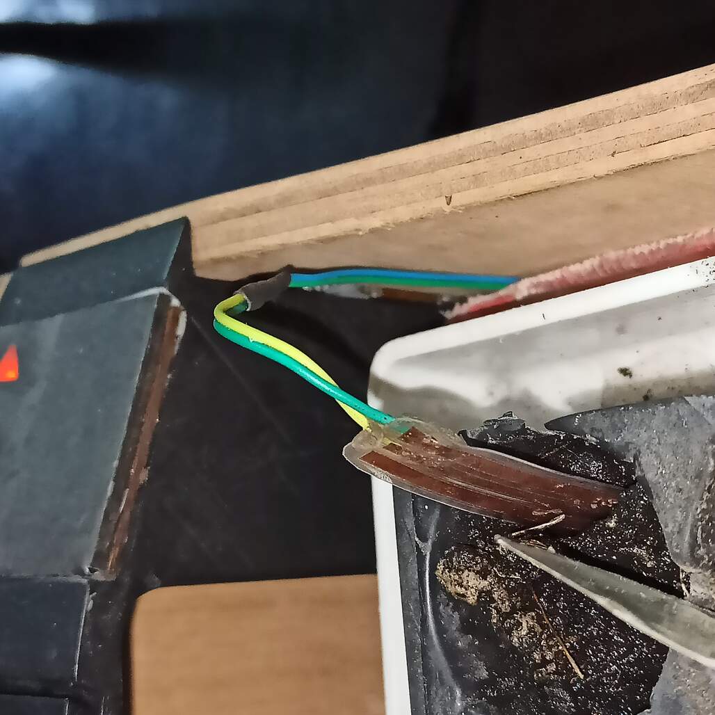
While I was testing and programing the water sensor board a short circuit occur and burn the AtTiny1614 of the water sensor and the AtTiny412 of the light sensor, this meant I have to replace them, I use a heat gun to desolder and solder the new ones... This cost me some valuable time but luckily is now solved.
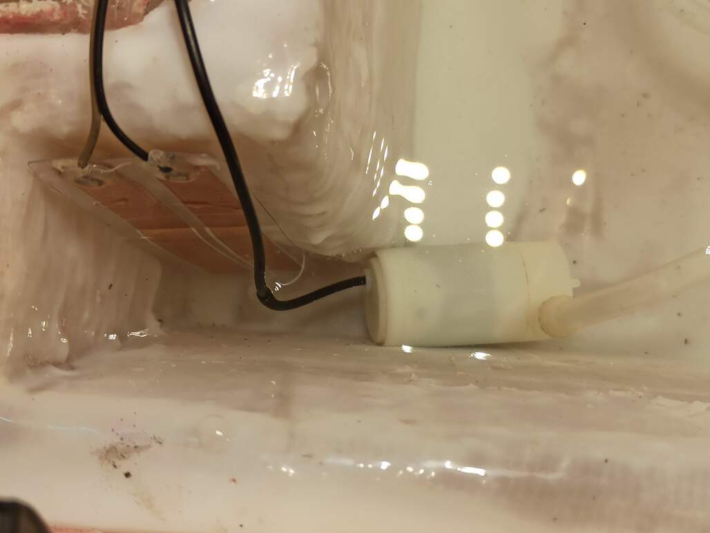
Pump and water tank level sensor on place, soil moisture sensor ready to be placed on the plant soil.
But on the end it worked out
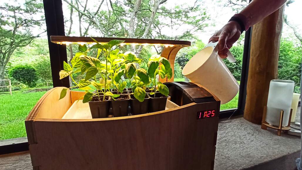
Time lapse of the final assembly on the actual place it will be installed, also I full up the water tank to set it up to normal operation.
Final graph of the features fabricated, and pending of the final project