Computer-Controlled Machining

Jump to the hero-shot

Designing for CNC machining

As for any type of digital fabrication you have to consider some important aspects while designing for the CNC router. First decide if you want to use 2d, 2.5, 3, 4, 3+2, 5 axis machining.

An important idea is that you may use a different method for each piece, and combine techniques or approaches, as an example if you need to make a big pocket or indentation is better to make a rough 2.5 layer-based pass, and then a detailed surface finish, this can be done with a smaller step-over or a 3d path.

More in-depth concepts to be aware of while designing for CNC milling can be found on this useful page.

Dog bones / T bones

To understand why we need to implement this type of fillet on interior corners, we should consider that a rounded mill bit will let a rounded corner and it can't make sharper corners than its own diameter. This can cause some problems when assembling the final pieces, especially if used on a precision joint like press fit. More info can be found on this useful page

T bone vs dog bone

T bone and dog bone differences 
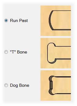
Illustation by Mozaik

You can use three filets to overcome this issue, the run past that creates an arc that can compensate the tool diameter, but it leaves a bigger impact. The T bone place the circles center on tangency from one of the lines, you can choose which one and use this to hide it. The dog bone is placed in the middle so both lines will end up with a small feature.

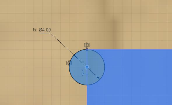
Below you can see some examples of how to constrain T bones and dog bones using Fusion 360, I think that similar methods can be used on other programs.

T bone sketch Dog bone sketch

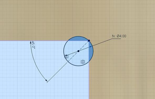
The following video has a nice explanation about CNC fillets and how to draw them.

plant crib 0.1 assembled

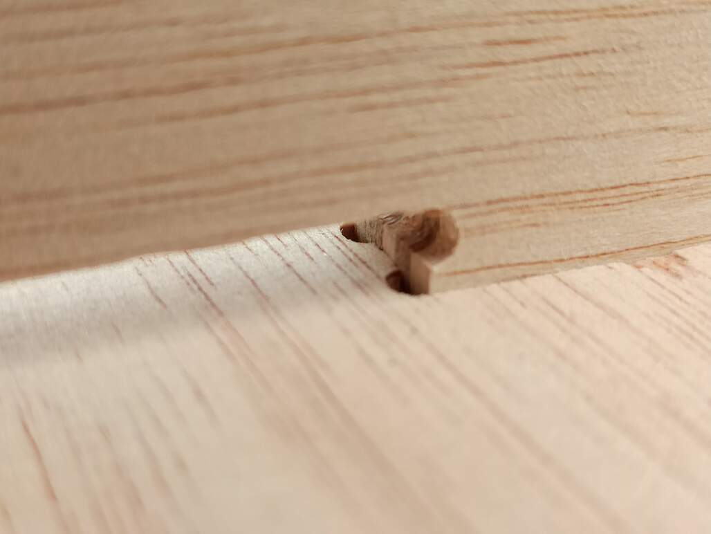
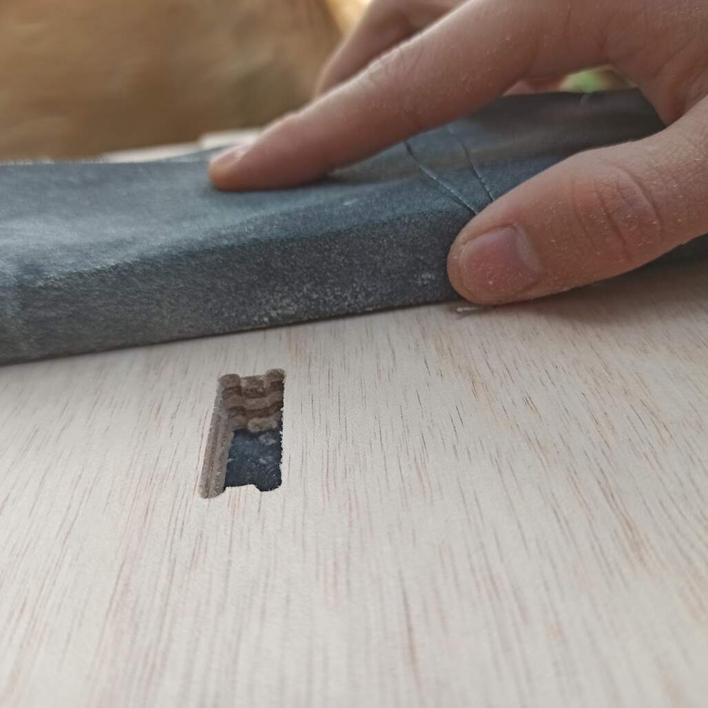
As you can see I use T bones that will be hidden when the joint is fully closed. This can make your design more visually appealing and also be ready for the machining process/


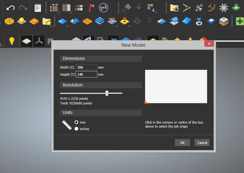
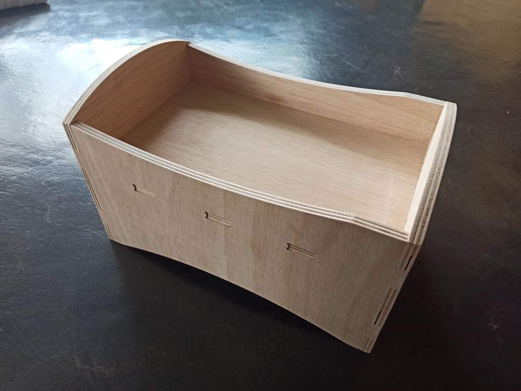
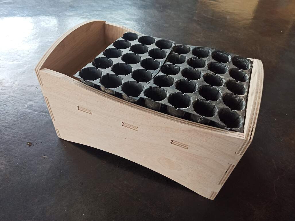
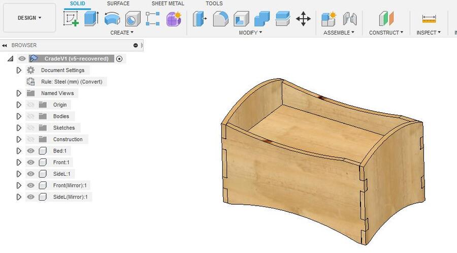
How I design my object

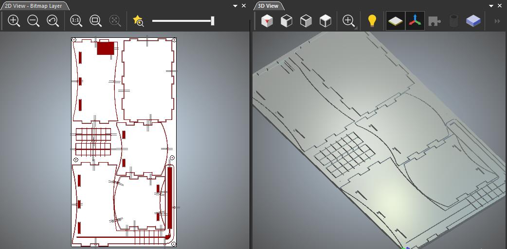
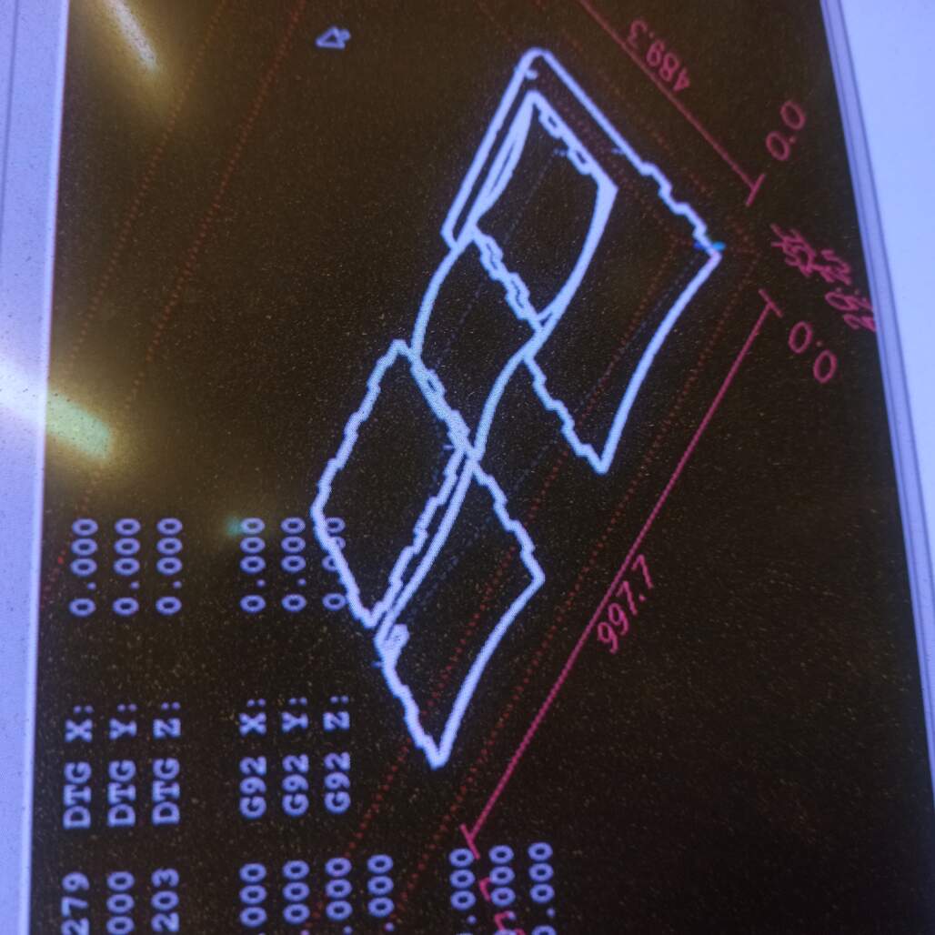
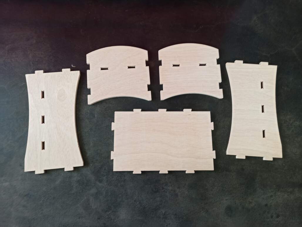
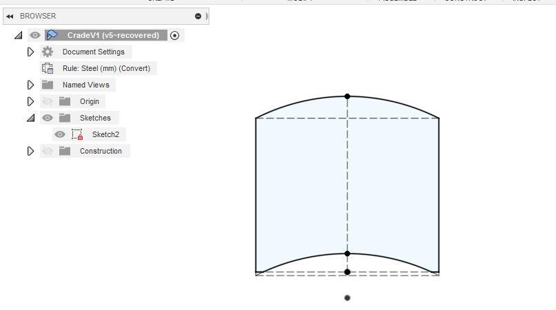
I use Fusion 360 as my CAD program, I started sketching the side view following the hand-drawn sketch made in the first week, then I extruded the faces and make the side pieces, cutting some features with a side sketch. Then I created a sketch for the tabs, extrude that, and use the combine tool to make the appropriate holes on the other pieces.

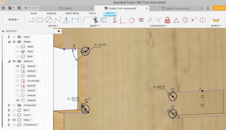
After some CNC basics class in the Lab, I was sure about the tabs and how I will make the joints, so I started placing the dog bones on a separate sketch, the problem was that I didn't use the correct anchoring on the sketches and the dog bones were out of place. I have to re-do some of the dog bones to finally get it right.

Crib side sketch Dog bone sketch detail Final crib model

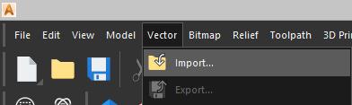
Get the .f3d design file! Get the .dxf file!


Group assignment

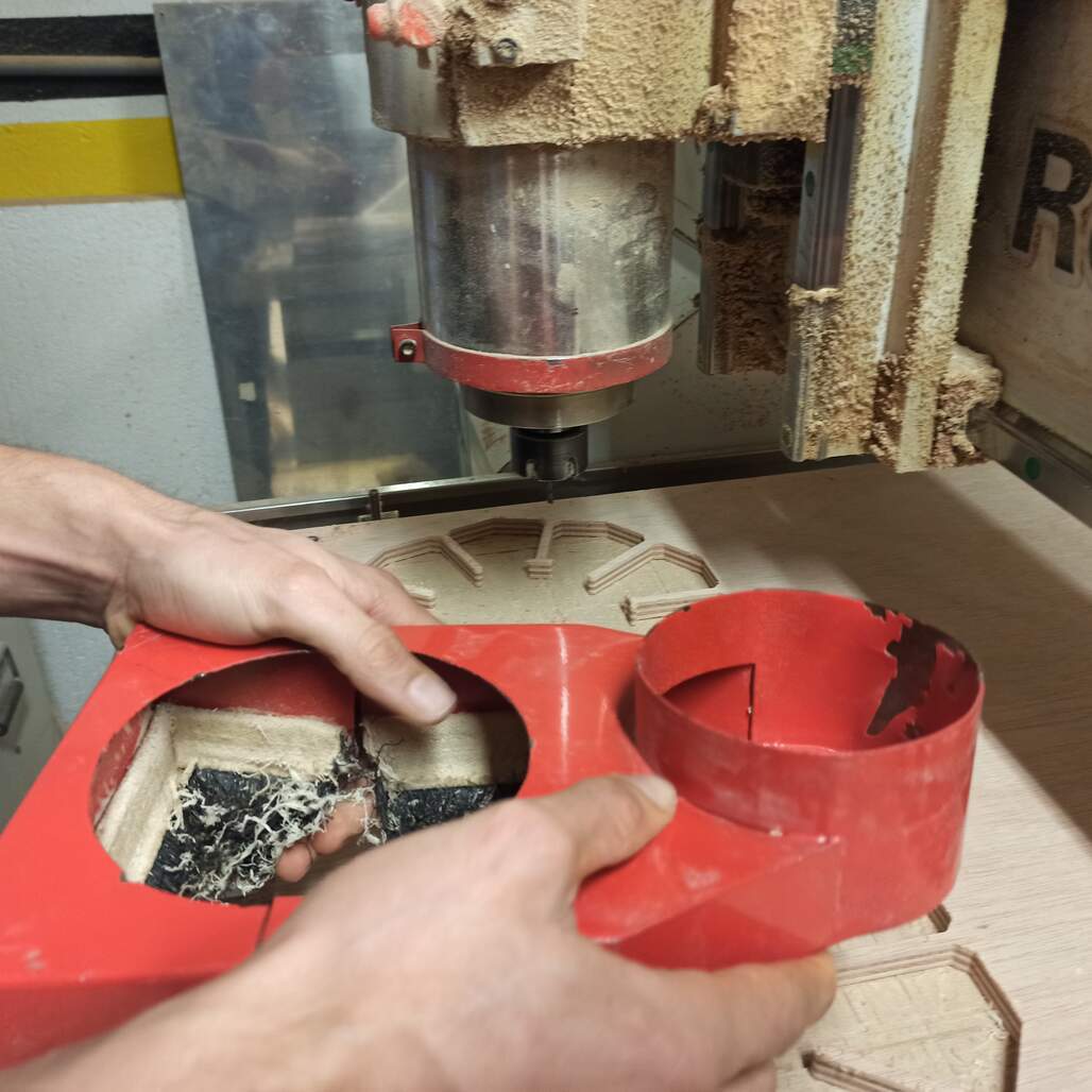
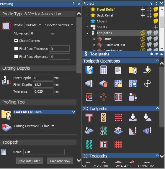
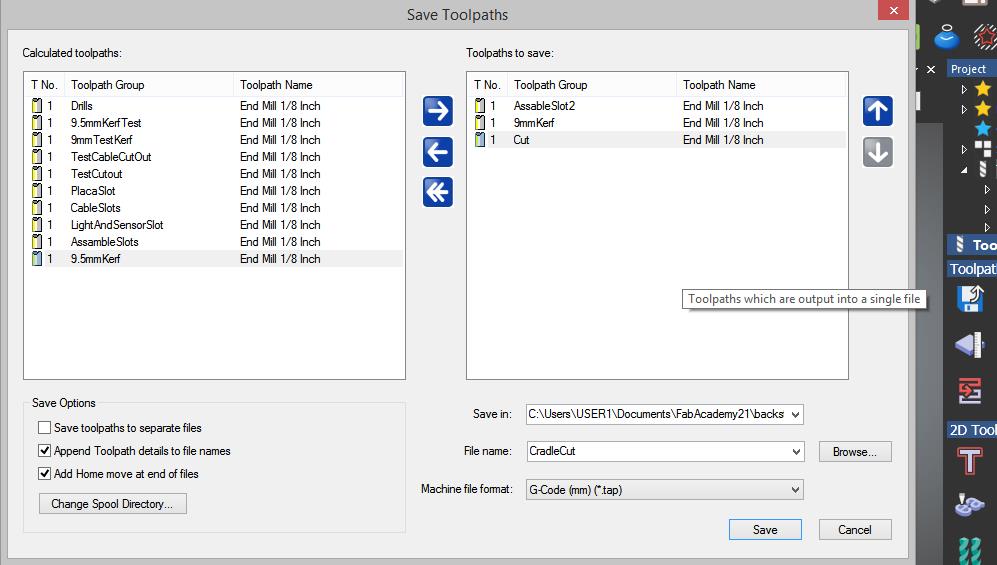
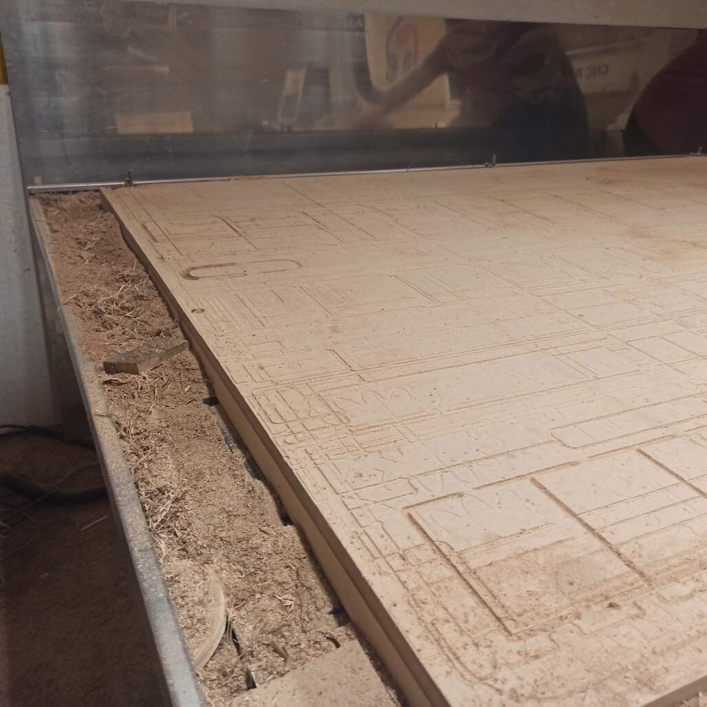
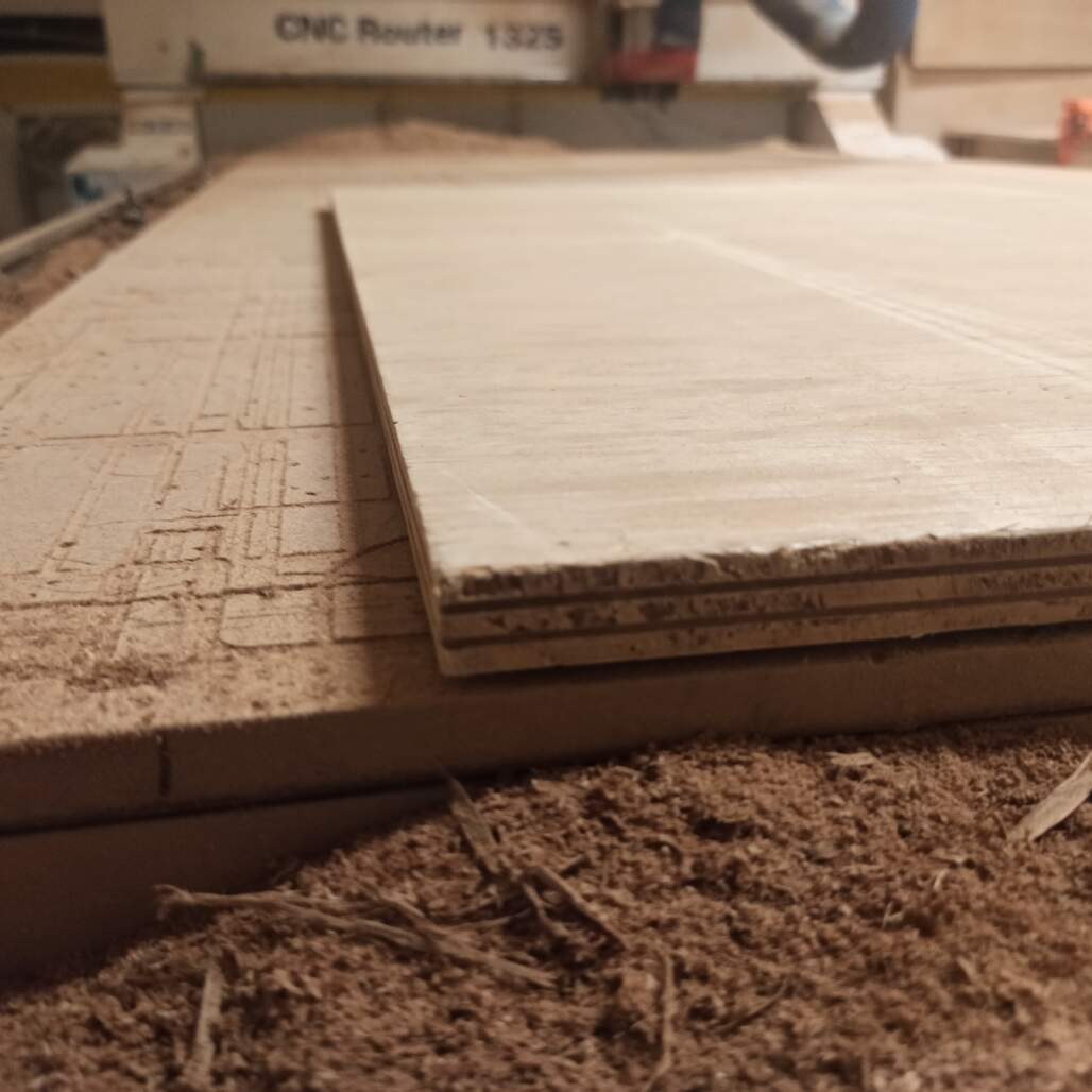
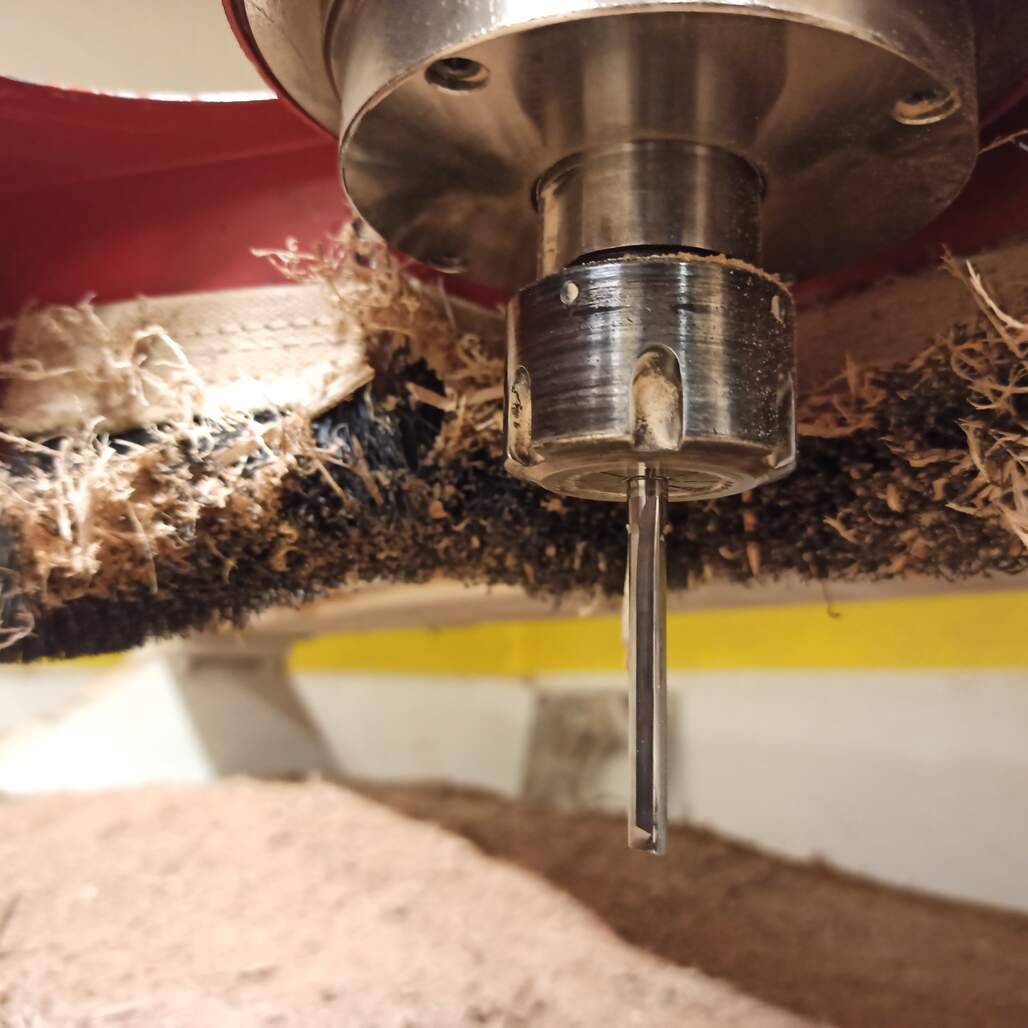
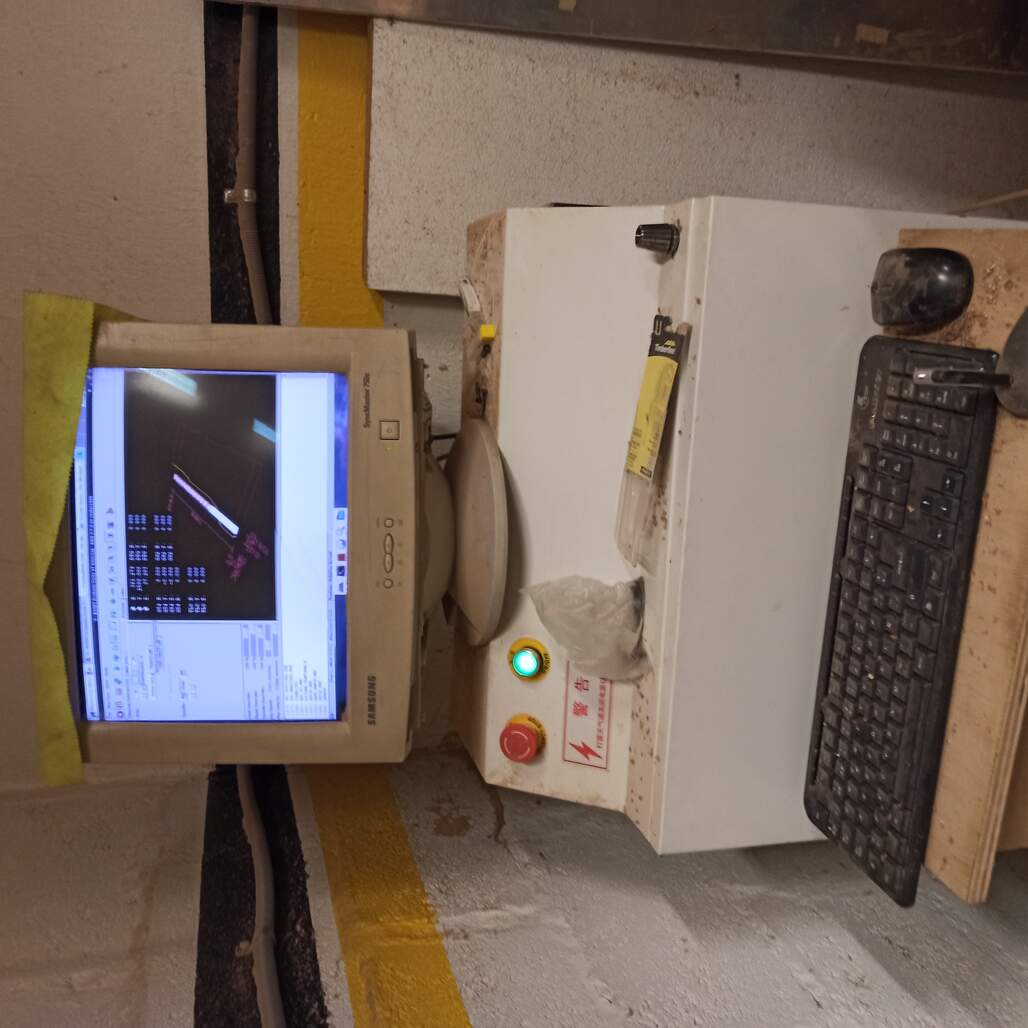
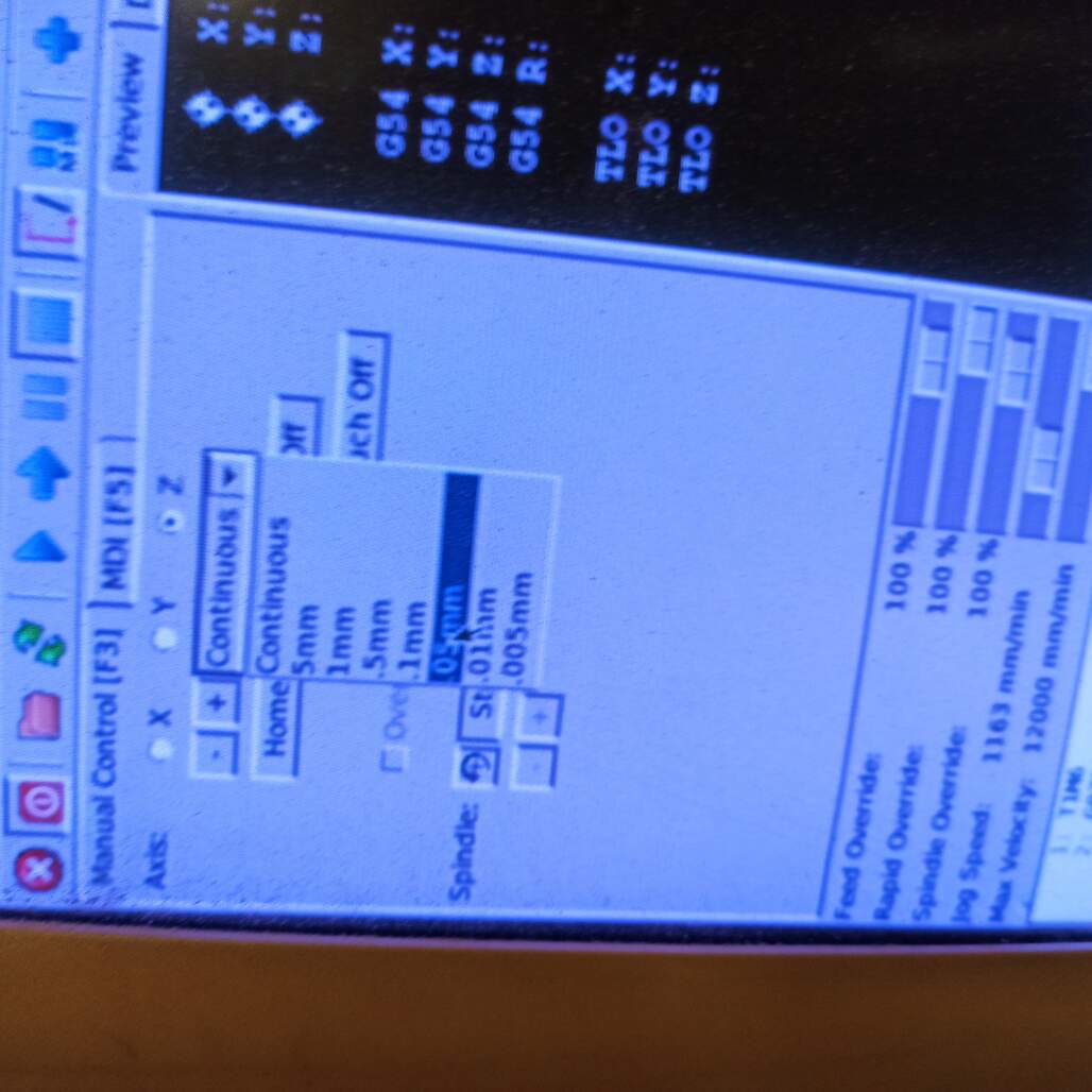
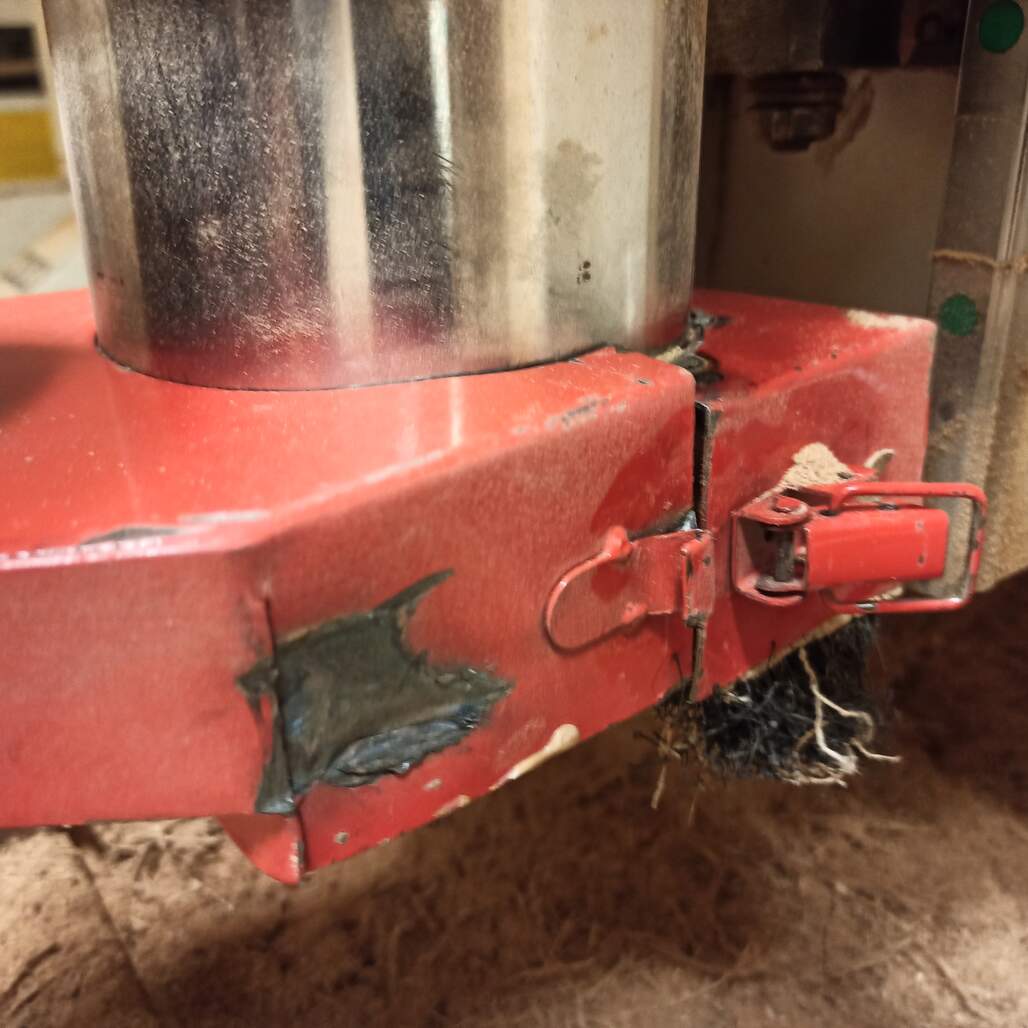
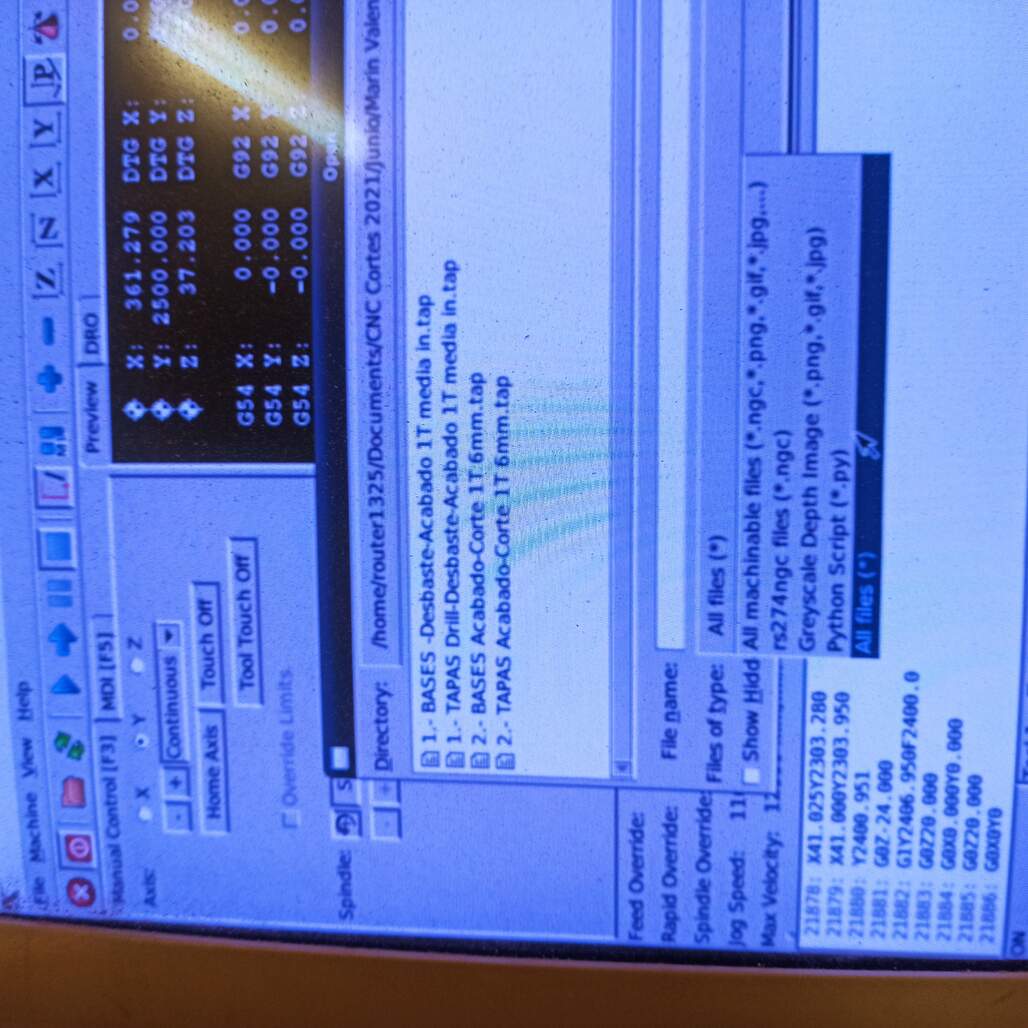
This week we characterize the safety rules of the CNC router and explore the capabilities and limitations of this technique of manufacturing.

See our group page!
Camilo setting up the dust collector


Making the toolpath

Screen shot of the Artcam icons

For this, we use the Artcam 2008 software, as it has a lot of useful icons and is easier to understand when is your first time generating multiple toolpaths that are correlated.

Also, the fab has a kit of preset tools made for this program, there is included the available mills and settings for the specific CNC router (CNC Router 1325).

The process to make the toolpaths goes as followed

  1. First, create a new project with the right XY dimensions (based on the raw material to be milled).
  2. Then you import your design files, as .DXF or other supported formats.
  3. If needed use the path doctor tool to find duplicates or open lines.
  4. Make a drill pattern that will be used to hold your raw material to the CNC bed. Set up your drill or mill bit to the one you will be using on the machine and the drill depth on only 2mm.
  5. Make your mill path by selecting the corresponding vector, setting up the mill bit settings, and material settings.
  6. Make as many paths as you need depending on your approach or desired finish. Be sure that the order is correct to avoid issues.
  7. Create bridges that will hold the material in place while the machine is cutting and are easily removed after. (4x5 mm for a 12mm material)
  8. Export the paths to G-code, be sure to use a codec that your machine understand.(G-code (mm) .tap)
  9. You can simulate it to test how it works using the G-Code Q'n'dirty toolpath simulator
Artcam setting up the material Artcam saving the toolpaths as g code Setting up the tool

We use a 1/8 inch end mill to make the cuts, the idea was to have a small enough mill that the dog-bones can be smaller and less noticeable,it was configured usign a 0.953mm step over, 3mm step down, 50 mm/s feed rate and 50 mm/s plunge rate, which work fine on the 12mm plywood.

Using Artcam 2018

On my first approach to generating toolpaths, we learn how to do it on artcam 2008 using a computer from the lab, but for the next assignments I download and install the 2018 version and re learned by exploring all the menus and icons. It take a long time but also give me a great understanding on how to make multiple toolpaths jobs and also how to simulate each one and see the effect when you change the step over or other settings.

How to create a new model on artcam

On this image you can see how to create a new model on artcam, you set up the width and height as well as the origin, (orange detail, placed on the lower-left corner).

How to import a vector into artcam

How to import a vector, it goes to the selected layer.

How to create a new model on artcam

On the right you can see the different toolpaths options that you can generate, 2D and 3D. On the left there is an example cut toolpath generated to cut the crib v1.0, There you can select the tool and change the, step over, speed rates and step down.

How to create a new model on artcam

Here you can see the export toolpath menu, on the left you have the list of all the toolpaths available, once you select one you can 'stage' it using the blue arrows. Also you can reorder them. Using the checkboxes you can merge multiple toolpaths that use the same tool into one file, or save them as separate, also append the details to file name is nice because it adds the name of the used tool (mill bit).

Tool path sipulation

Here you can see an example of the simulation of the toolpaths, this allows you to test how the parameters will behave. And have a visual idea of what you are doing.

Using Mods

You can also use mods to generate the G-code, the process is similar a what was described on the electronics-production week. You can transform your .dxf file to png using Illustrator or export as .SVG, mods also have programs to make 2.5 toolpaths but that's something to be explored and tested yet.

Let's Make it!

Before making the actual milling process you have to load the material, set the machine origin and run the drill path and secure it with screws. Also, check that the dust collector system is ready. Run the G-code and always follow the safety recommendations.

How To make a CNC machine job

Following the next steps you will be able to load the desired material and prepare the mill bit to cut or mill.

Cnc bead clean

Clean the sacrificial layer from the last material chips

Material loaded

Load the material on the bed, make sure it is as flat as possible and squared with the border.

6 mm mill

Change the mill bit if need to, in this case a 3 mm flat end mill, note you should also use the correct size collet.

First you should take care of the material and mill bit, make sure to use the correct collet, clean it from any debris of dust from previous uses. Also measure the material to ensure it is suitable for what you designed. Make adjusting on nesting or toolpaths if needed.

Set up the axis origins, use the arrow keys to move along the X/Y plane, set those axis first, usually to the lower left corner. Then spin up the mill bit and move down the z-axis until you nearly touch the material surface. Use smaller steps on the last part to ensure precision, home this axis as well. Then you should load the fixing drill toolpath and run it.

Picture of the controller computer

Here you can see the controller computer and the power button, also note the placement of the emergency stop button.

Micro steps used to set up the z axis

Use this setting to set up the z axis origin. Leave on continuos to preform may other movement.

Close the dust collector piece

Once the z-axis is homed you should close the dust collector piece, make sure to place the security pin.

Once that toolpath is finished use the hand drill ans screws to fix the material on place. Load the job toolpath, then run the program, first step by step until the spindle reaches the set speed and the you can run it continuously. The order matters, you should run first all the pockets and/or slots toolpaths and then the final cut.

Picture of the controller computer

Open the .tap file, make sure you select all files option. Choose the fixing drills first.

Micro steps used to set up the z axis

Use screws to secure the material to the cnc bed, secure them using the hand drill make sure they fix the material on place.

Micro steps used to set up the z axis

Here you can se the preview of the loaded .tap file. Double check the size and scale.

When finished, remove your pieces and then the screws. Unload the exes material and if it is re-usable pile. Clean up the place and leave it as you want to find it.

After the CNC job was completed I took my pieces home, at the next day I sanded them down to eliminate any cut chip and any remaining of the bridges, the I use a hammer and some scrap wood to assemble the final crib, without any fixing or glue, it is just built by the friction on the joints.

As intended the joints were to tight together that some didn't assemble at the first try but a little bit of sanding was enough to make they work.

Note: is important to use some scrap wood as an intermediate between the hammer and the pieces to avoid little hammer marks, you can also use a rubber hammer if you have one.

Sanding process plant crib 0.1 pieces after some sanding ready to be assembled

Plant Crib v0.1

plant crib 0.1 assembled
plant crib 0.1 pieces before assembling plant crib 0.1 assembled width plant places ready

Conclusions

This week was really fun, at first I was afraid of my joints been too tight and that causing problems to the final assembly but with a little bit of sanding I was able to fit the joints and assemble the final shape, I think it would require a lot of sanding but at the end, I only need a normal sanding for the appearance and then 4 - 5 passes on the joints to make it fit properly.

Even though the final object isn't that BIG (40cm x 25cm x 23cm) I'm happy with the end result as it is an approximation of the final shape my project would have, just holding this 'plant crib' on my hands make me feel excited about what I would do and make my project idea close to reality.

Have I?


Prev Next